Hangar 9 P-51D Mustang Sport 40 ARF Assembly Manual
Hide thumbs
Also See for P-51D Mustang Sport 40 ARF:
- Instruction manual (113 pages) ,
- Instruction manual (77 pages) ,
- Instruction manual (112 pages)
Table of Contents
Advertisement
Quick Links
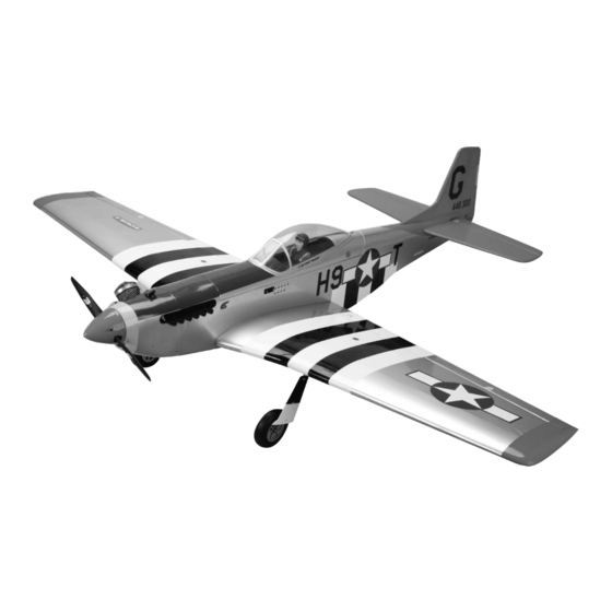
P-51D Mustang Sport 40 ARF
Assembly Manual
Specifications
Wingspan: ......................................................... 58.25 in (1480mm)
Length: ................................................................ 50.4 in (1281mm)
Wing Area: ................................................626 sq in (40.39 sq dm)
Weight: ........................................................... 6.5–7 lb (2.9–3.2 kg)
Radio: ...............................................4- to 6-channel w/5-8 servos
Engine: ................................................ .40–.46 2-stroke, Power 46
Advertisement
Table of Contents

Related Manuals for Hangar 9 P-51D Mustang Sport 40 ARF


Summary of Contents for Hangar 9 P-51D Mustang Sport 40 ARF
- Page 1 P-51D Mustang Sport 40 ARF Assembly Manual Specifications Wingspan: ............58.25 in (1480mm) Length: ..............50.4 in (1281mm) Wing Area: ..........626 sq in (40.39 sq dm) Weight: ............6.5–7 lb (2.9–3.2 kg) Radio: ..........4- to 6-channel w/5-8 servos Engine: ..........40–.46 2-stroke, Power 46...
-
Page 2: Table Of Contents
Age Requirements ...............51 (Includes mounting blocks, not Safety, Precautions and Warnings ........51 shown) Warranty Information ............51 Compliance Information for the European Union ....52 2009 Official Academy of Model Aeronautics Safety Code ..53 Hangar 9 P-51D Mustang Sport 40 Assembly Manual... -
Page 3: Included Parts Listing
Gear door (left and right) 4-40 x 3/4 socket head cap screw wing attachment Wire tie gear doors #4 flat washer wing attachment #4 lock washer wing attachment Hangar 9 P-51D Mustang Sport 40 Assembly Manual... -
Page 4: Important Information Regarding Warranty
Spektrum DX6i SPM6600 Spektrum DX7 SPM2710 JR Systems X9303 2.4GHz JRP2915 The Spektrum trademark is used with permission JR Systems 12X 2.4GHz JRP1200 of Bachmann Industries, Inc. Hangar 9 P-51D Mustang Sport 40 Assembly Manual... -
Page 5: Optional Retracts
23/4-inch (70mm) Main Wheels (HAN305) Thin CA (PAAPT08) Robart Air Pump (ROB164G) Threadlock (PAAPT42) DS821 Digital Sport Servo (JRPS821) or 30-Minute Epoxy, 8 oz (PAAPT39) MN48 Mini Servo (JSP20040) Hinge Glue (PAAPT55) Hangar 9 P-51D Mustang Sport 40 Assembly Manual... -
Page 6: Preparing The Fuselage For Electric Power
3-inch 6-inch (152mm) extension (electronic speed control) (76mm) 5-inch 9-Channel receiver (127mm) 6-inch (152mm) (2) (ailerons) 6-inch (152mm) (2) (flaps) 2-inch (51mm) 3-inch (76mm) extension (retracts) 6-inch (152mm) extension (electronic speed control) Hangar 9 P-51D Mustang Sport 40 Assembly Manual... - Page 7 Hint: Place a drop of light oil in the hatch pin from the inside of the canopy hatch so it will operate smoothly. Hint: If you are installing a glow engine, prepare a third servo for use as the throttle servo. Hangar 9 P-51D Mustang Sport 40 Assembly Manual...
- Page 8 3: If you are building your model for use with an electric power system, plug a 6-inch (152mm) extension in the throttle port of the receiver. Hangar 9 P-51D Mustang Sport 40 Assembly Manual...
- Page 9 Mount the remote receiver inside the fuselage using hook receiver area. The amount of foam will be dependant on your and loop material. Note the direction of the antenna on choice of receiver. the receiver. Hangar 9 P-51D Mustang Sport 40 Assembly Manual...
-
Page 10: Installing The Rudder And Elevator Pushrods
With the radio on and the elevator servo horn so it doesn’t interfere with the operation of the servos. centered, secure the servo horn to the elevator servo using the screw from the servo and a #1 Phillips screwdriver. Hangar 9 P-51D Mustang Sport 40 Assembly Manual... -
Page 11: Installing The Tail Surfaces
Slide a clevis retainer on one of the nylon clevises. Thread the clevis 12-turns on the elevator pushrod. The exact position of the clevis will be adjusted once the tail has been bolted to the fuselage. Hangar 9 P-51D Mustang Sport 40 Assembly Manual... - Page 12 Step 3 Position the stabilizer/elevator assembly so the control horn will face down, away from the fin. The threaded rods from the rudder/fin assembly will slide into the two holes in the stabilizer. Hangar 9 P-51D Mustang Sport 40 Assembly Manual...
-
Page 13: Installing The Glow Engine
Locate the items necessary to attach the engine to the fuselage. note: Once the rudder and elevator are adjusted, slide the clevis retainer over the forks of the clevis so it does not open accidentally. Hangar 9 P-51D Mustang Sport 40 Assembly Manual... - Page 14 Step 6 will face up and away from the engine when installed. Slide the engine into position. The engine mount straps will be on the top of the engine mount lugs as shown. Hangar 9 P-51D Mustang Sport 40 Assembly Manual...
- Page 15 Use medium grit sandpaper to roughen the ends of the pushrod tube. Slide the pushrod tube into the hole so it is flush with the firewall. Use medium CA to glue the pushrod in position. Hangar 9 P-51D Mustang Sport 40 Assembly Manual...
- Page 16 Insert the Z-bend made in the throttle pushrod in the outside hole of the carburetor arm. You may need to remove the carburetor arm or engine to slide the pushrod wire into the tube inside the fuselage. Hangar 9 P-51D Mustang Sport 40 Assembly Manual...
- Page 17 Use the transmitter to check that the carburetor will fully open. You may need to fine-tune the endpoints at the radio if it doesn’t open fully, or if the servo binds at full throttle. Hangar 9 P-51D Mustang Sport 40 Assembly Manual...
-
Page 18: Installing The Fuel Tank, Cowling And Spinner For Glow Installations
Secure the tank in the fuselage using two 4-40 x 5/8-inch socket head screws and two #4 washers and the fuel tank stay. Tighten the screws using a 3/32-inch hex wrench or ball driver. Hangar 9 P-51D Mustang Sport 40 Assembly Manual... - Page 19 The Dubro spinner will include adapters to fit a variety of engine shafts. Make sure to select the correct adapter for your application. note: The spinner is not included and will need to be purchased separately. Hangar 9 P-51D Mustang Sport 40 Assembly Manual...
- Page 20 Slide the cowling forward to expose the holes in the fuselage. Place 2–3 drops of thin CA in each of the four holes to harden the surrounding wood. This will help prevent the screws from vibrating loose. Hangar 9 P-51D Mustang Sport 40 Assembly Manual...
- Page 21 #2 x 5/16-inch wood screws. note: The exhaust stack for the right side of the model is shorter than the left. This is necessary to clear the muffler. Hangar 9 P-51D Mustang Sport 40 Assembly Manual...
-
Page 22: Installing The Electric Motor
Secure the speed control inside the fuselage as shown. Pass machine screw. Prepare four screws at this time. the leads for the motor through the narrow slot made in the firewall at the beginning of this manual. Hangar 9 P-51D Mustang Sport 40 Assembly Manual... -
Page 23: Installing The Cowling And Spinner For Electric Motor Installations
It should rotate counterclockwise when viewed from the front of the fuselage. If it does not, read through the instructions for the speed control to correct the direction of rotation. Hangar 9 P-51D Mustang Sport 40 Assembly Manual... - Page 24 Hint: Starting the screw partially in the exhaust stack will help in getting the screw started in the pre-drilled holes in the cowling and fuselage. note: The spinner is not included and will need to be purchased separately. Hangar 9 P-51D Mustang Sport 40 Assembly Manual...
-
Page 25: Installing The Pilot And Canopy
Lightly sand the inside edge of the canopy using medium grit sandpaper. Apply a bead of canopy glue to the canopy and position it on the canopy hatch. Use low-tack tape to keep the canopy in position until the glue fully cures. Hangar 9 P-51D Mustang Sport 40 Assembly Manual... - Page 26 The right and left servos will have the servo arm facing different directions. If the servo does not rest fully on the cover, you may need to rotate the servo horn 180-degrees. Hangar 9 P-51D Mustang Sport 40 Assembly Manual...
- Page 27 This will help in preventing the screws from vibrating loose. Step 12 Position the servo between the servo mounting blocks. Use a pencil to transfer the positions for the screws to the mounting blocks. Sand this end Hangar 9 P-51D Mustang Sport 40 Assembly Manual...
- Page 28 Slide a clevis retainer on a nylon clevis. Step 18 Secure the servo cover to the wing using four #2 x 3/8-inch self-tapping screws and a #1 Phillips screwdriver. Hangar 9 P-51D Mustang Sport 40 Assembly Manual...
-
Page 29: Installing The Fixed Flaps
Use four #2 x 3/8-inch self-tapping screws to secure the flap servo cover to the wing. Step 1 Locate the items necessary to install the aileron servos. Step 22 Repeat Steps 11 through 21 to complete the servo installation. Hangar 9 P-51D Mustang Sport 40 Assembly Manual... -
Page 30: Installing The Optional Flap Servos
Repeat Steps 1 through 6 to install the remaining flap linkage. Make sure to adjust the flap on both the left and right wing panels or you may have difficulty trimming the roll (aileron) of your P-51D Mustang. Hangar 9 P-51D Mustang Sport 40 Assembly Manual... - Page 31 Sand this end Hangar 9 P-51D Mustang Sport 40 Assembly Manual...
- Page 32 This can easily be done by scoring the stay near the wing and bending it slightly, which will break the flap stay where it was scored. Hangar 9 P-51D Mustang Sport 40 Assembly Manual...
- Page 33 The best way to set the flaps is to set the endpoints for the flap travel to 0. You can then adjust the travel to achieve the correct up and down flap settings using your radio. Hangar 9 P-51D Mustang Sport 40 Assembly Manual...
-
Page 34: Installing The Fixed Landing Gear
Step 23 Repeat Steps 10 through 22 to complete the servo installation. Hangar 9 P-51D Mustang Sport 40 Assembly Manual... - Page 35 Step 4 Note there is a flat area on the main gear strut. This will align with the hole in the mount for the setscrew. Hangar 9 P-51D Mustang Sport 40 Assembly Manual...
-
Page 36: Optionalinstalling The Retract Actuator
Locate the necessary items to install the retract servo and actuator valve in the fuselage. Step 8 Repeat Steps 2 through 7 to attach the remaining main landing gear to the wing. Hangar 9 P-51D Mustang Sport 40 Assembly Manual... - Page 37 Step 9 valve. Place a T-fitting on the opposite end of the air line. Cut a 3-inch (76mm) piece of air line to connect the actuator valve to the T-fitting as shown. Hangar 9 P-51D Mustang Sport 40 Assembly Manual...
- Page 38 3/8-inch (10mm) from the center of the servo horn. Step B Place the servo in the tray as shown. Use a pencil to tansfer the locations for the servo mounting screws on the tray. Hangar 9 P-51D Mustang Sport 40 Assembly Manual...
- Page 39 Important: The pin in the clevis must be positioned vertically as shown in the photos. If the pin is not vertical it will cause premature wear on the valve and it will begin to leak and not operate correctly. Hangar 9 P-51D Mustang Sport 40 Assembly Manual...
- Page 40 Locate the air tank mount. Note the narrow side of the mount as the top of the mount. Step 19 Cut a 6-inch (152mm) piece of air line and attach it to the air tank. Hangar 9 P-51D Mustang Sport 40 Assembly Manual...
- Page 41 Cut three 3-inch (76mm) pieces of air line. Assemble the out through the holes in the sides of the fuselage as shown. connector as shown below using the three pieces of air line, two connectors and a T-fitting. Hangar 9 P-51D Mustang Sport 40 Assembly Manual...
-
Page 42: Optionalinstalling The Retract Mechanism
1/2-inch socket head screws and #6 washers to hold the template in position. Adjust the position of the template so the rear edge of the template is 3 -inch (100mm) from the front edge of the wing mounting tab as shown. Hangar 9 P-51D Mustang Sport 40 Assembly Manual... - Page 43 Once everything has cured, use a trim seal sure to use threadlock on the screws so they don’t vibrate tool to neatly iron the covering back on the wing and into the loose in flight. wheel well as shown. Hangar 9 P-51D Mustang Sport 40 Assembly Manual...
- Page 44 Make sure to check that you are Also check that the wheel is centered in the wheel well. placing the flat on the correct side for each wing panel. Hangar 9 P-51D Mustang Sport 40 Assembly Manual...
-
Page 45: Attaching The Wing
Step 2 Locate the aileron Y-harness inside the fuselage. Make sure one end of the harness exits the right side of the fuselage and one exits the left side of the fuselage. Hangar 9 P-51D Mustang Sport 40 Assembly Manual... -
Page 46: Center Of Gravity
If not, self stick weights must against the fuselage. Repeat Steps 5 and 6 to secure the be added to correct any balancing problems. wing panel to the fuselage. Hangar 9 P-51D Mustang Sport 40 Assembly Manual... -
Page 47: Control Throws
Tail Heavy – Add Weight to Nose After the first flights, the CG position can be adjusted for your personal preference. Hangar 9 P-51D Mustang Sport 40 Assembly Manual... -
Page 48: Safety Do's And Don'ts For Pilots
8-cells to power the transmitter. Do not fly if the receiver pack is at or below 4.7V. To do so can crash your aircraft. note: When you check these batteries, ensure that you have the polarities correct on your expanded-scale voltmeter. Hangar 9 P-51D Mustang Sport 40 Assembly Manual... -
Page 49: Flying Your P-51 Mustang
Also check the nylon connectors at the servo for any wear or damage. If they look worn or in bad shape, replace them as well. Hangar 9 P-51D Mustang Sport 40 Assembly Manual... -
Page 50: Glossary Of Terms
• Leading Edge: The front of a flying surface. • Main Landing gear: The wheel and gear assembly the airplane uses to land. It is attached to the bottom of the fuselage. Hangar 9 P-51D Mustang Sport 40 Assembly Manual... -
Page 51: Age Requirements
For questions or assistance, please by Purchaser must be approved in writing by Horizon before direct your email to productsupport@horizonhobby.com, or shipment. call 877.504.0233 toll free to speak to a service technician. Hangar 9 P-51D Mustang Sport 40 Assembly Manual... -
Page 52: Compliance Information For The European Union
Please call +49 4121 46199 66 or e-mail us at service@ horizonhobby.de with any questions or concerns regarding this product or warranty. Hangar 9 P-51D Mustang Sport 40 Assembly Manual... -
Page 53: 2009 Official Academy Of Model Aeronautics Safety Code
Model Rocketry Safety Code; however, they may not be launched from model aircraft. Officially designated AMAAir Show Teams (AST) are authorized to use devices and practices as defined within the Air Show Advisory Committee Document. Hangar 9 P-51D Mustang Sport 40 Assembly Manual... - Page 54 BuILDIng AnD FLYIng noTES Hangar 9 P-51D Mustang Sport 40 Assembly Manual...
- Page 55 BuILDIng AnD FLYIng noTES Hangar 9 P-51D Mustang Sport 40 Assembly Manual...
- Page 56 Horizon Hobby UK Horizon Technischer Service Horizon Hobby USA Units 1-4 Ployters Rd Hamburger Strasse 10 4105 Fieldstone Road Staple Tye 25335 Elmshorn Champaign, Illinois 61822 Harlow, Essex Germany CM18 7NS +49 4121 46199 66 (877) 504-0233 United Kingdom +44 (0) 1279 641 097 ©...
Need help?
Do you have a question about the P-51D Mustang Sport 40 ARF and is the answer not in the manual?
Questions and answers