Hangar 9 P-51 Mustang ARF Assembly Manual
Hangar 9
Hide thumbs
Also See for P-51 Mustang ARF:
- Assembly manual (72 pages) ,
- Instruction manual (48 pages) ,
- Installation manual (7 pages)
Table of Contents
Advertisement
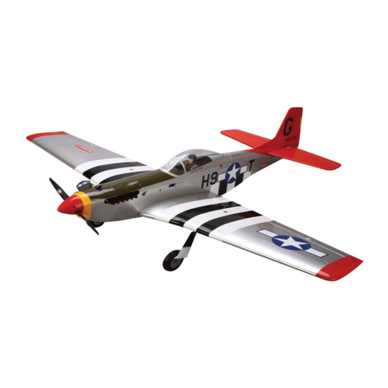
P-51 Mustang ARF
Specifications
Wingspan: ............... 58.25 in (1480mm)
Length: .................... 50.5 in (1284mm)
Wing Area: .............. 603 sq in (38.92 sq dm)
Assembly mAnuAl
Weight: .................... 6.5–7 lb (2.9–3.2 kg)
Radio: ..................... 4-channel w/5 servos
Engine: .................... Evolution TPS
Advertisement
Table of Contents

Related Manuals for Hangar 9 P-51 Mustang ARF


Summary of Contents for Hangar 9 P-51 Mustang ARF
- Page 1 P-51 Mustang ARF Assembly mAnuAl Specifications Wingspan: ....58.25 in (1480mm) Weight: ....6.5–7 lb (2.9–3.2 kg) Length: ....50.5 in (1284mm) Radio: ..... 4-channel w/5 servos Wing Area: ....603 sq in (38.92 sq dm) Engine: ....Evolution TPS...
-
Page 2: Table Of Contents
Section 21: Maintaining Your P-51 Mustang ARF ........ -
Page 3: Contents Of Kit
Contents of Kit Replacement Parts Fuselage HAN2826 Wing w/Aluminum Tube HAN2827 Belly scoop HAN2828 Tail set HAN2829 Canopy HAN2830 Cowl HAN2831 Landing Gear Set w/Wheels and Speed Brakes HAN2832 Aluminum Wing Tube HAN2833 Droops HAN2835 10. Exhausts HAN2836 11. Propeller EVOE100P Items not shown Speed Brake Set... -
Page 4: Covering Colors
Covering Colors • Black HANU874 • White HANU870 • Silver HANU881 • Dark Yellow HANU889 Field Equipment Required • Fuel (10%–15% nitro content) • Glow Plug Wrench (HAN2510) • Glow Plug Igniter with Charger (HAN7101) • Glow Plug (HAN3001/3006) • Manual Fuel Pump (HAN118) or •... -
Page 5: Limited Warranty & Limits Of Liability
Limited Warranty & Limits of Liability Pursuant to this Limited Warranty, Horizon Hobby, Inc. will, at its option, (i) repair or (ii) replace, any product determined by Horizon Hobby, Inc. to be defective. In the event of a defect, these are your exclusive remedies. -
Page 6: Inspection Or Repairs
Ship via a carrier that provides tracking and insurance for lost or damaged parcels, as Horizon Hobby, Inc. is not responsible for merchandise until it arrives and is accepted at our facility. Include your complete name, address, phone number where you can be reached during business days, RMA number, and a brief summary of the problem. -
Page 7: Warranty Information
Warranty Information Horizon Hobby, Inc. guarantees this kit to be free from defects in both material and workmanship at the date of purchase. This warranty does not cover any parts damage by use or modification. In no case shall Horizon Hobby’s liability exceed the original cost of the purchased kit. -
Page 8: Section 1: Hinging The Ailerons And Flaps
Section 1: Hinging the Ailerons and Flaps Required Items: Step 2 • Wing (right and left) • Aileron (right and left) Drill a 1/16" (1.5mm) hole into the center of the three • Flap (right and left aileron hinge slots. This creates a tunnel so the thin CA used to glue the hinges can fully penetrate the hinge. - Page 9 Section 1: Hinging the Ailerons and Flaps Step 4 Step 6 Slide the aileron into position on the wing by guiding the Remove the T-pins from the hinges. Deflect the aileron hinges into the hinge slots in the wing. Push the aileron slightly without changing the hinge gap between the so there is little to no gap between the aileron hinge line.
- Page 10 Section 1: Hinging the Ailerons and Flaps Step 8 Step 9 Flex the aileron up and down a number of times to break Use a piece of sandpaper to roughen the flap linkage in the hinges. where it will extend into the flap.
- Page 11 Section 1: Hinging the Ailerons and Flaps Step 11 Step 13 Cut a piece of plastic from one of the bags the wing was Once the fit has been checked, remove the flap from the packaged in. Tape the plastic so it is between the wing and wing.
-
Page 12: Section 2: Aileron Servo Installation
Section 2: Aileron Servo Installation Required Items: • Wing (right and left) • Aileron servo cover (right and left) • 3/4" x 5/16" x 9/16" (19mm x 8mm x 14mm) servo mounting block (4) • 2mm x 8mm sheet metal screw Step 2 Photo Required Tools and Adhesives •... - Page 13 Section 2: Aileron Servo Installation Step 5 Step 7 Mix up about a tablespoon of 6-minute epoxy to glue Remove the servo and drill the locations marked in the the two 3/4" x 5/16" x 9/16" (19mm x 8mm x 14mm) previous step using a 1/16"...
- Page 14 Section 2: Aileron Servo Installation Step 10 Step 11 Photo Tie a wheel collar onto a piece of string. Lower the string into the opening for the aileron servo. Tip the wing so the tip is facing up and lower the string through the wing. Guide the string to exit the hole in the top of the wing near the root.
-
Page 15: Section 3: Installing The Aileron Linkage
Section 3: Installing the Aileron Linkage Required Items: Step 3 • Wing (right and left) With the aileron servo plugged in and the radio system • Aileron linkage wire (right and left) on, make sure the aileron servo is centered and the trim on the radio is centered. - Page 16 Section 3: Installing the Aileron Linkage Step 5 Step 7 Attach the clevis to the outer hole on the control horn. Use a T-pin to poke holes through the covering in the area Place the horn flat on the aileron, aligning the linkage inside the triangle made by the three holes.
- Page 17 Section 3: Installing the Aileron Linkage Step 9 Step 10 Attach the control horn to the wing using two 2mm x Locate the flap control horn. Thread the horn onto the flap 16mm screws near the hinge line of the control horn and linkage so the top of the horn is 7/8"...
-
Page 18: Section 4: Assembling The Wing
Section 4: Assembling the Wing Required Items: Step 3 • Left wing panel • Right wing panel Slide the panels tightly together, guiding the servo wires • Aluminum wing tube • Nylon strap out of the way. Use a nylon strap and two #2 x 5/16" sheet metal screws to secure the two wing panels together. -
Page 19: Section 5: Installing The Landing Gear
Section 5: Installing the Landing Gear Required Items: Step 2 • Assembled wing • Landing gear strap (4) Slide a second wheel collar onto the landing gear • 3 " (76mm) wheel (2) wire. Align the collar with the end of the landing gear wire. - Page 20 Section 5: Installing the Landing Gear Step 4 Step 6 Measure in 3/4" (19mm) from each end of the landing Locate the left landing gear strut. Slide the strut into gear slot. Position the landing gear strap so it straddles position on the bottom of the wing.
-
Page 21: Section 6: Installing The Engine
Section 6: Installing the Engine Required Items Step 2 • Fuselage • Engine mount Locate the engine mount plates, two 8-32 locknuts and • Engine mount plate (2) • 8-32 x 3/4" bolt (4) two 8-32 x 7/8" bolts. Slide the bolt through the smooth side of the engine mount plate. - Page 22 Section 6: Installing the Engine Step 3 Step 5 Position the engine onto the mount, sliding it between the Locate the 15 " (397mm) throttle pushrod wire. Slide a mount and the mounting plates. Slide the two remaining clevis retainer onto the clevis.
-
Page 23: Section 7: Cowling And Fuel Tank Installation
Section 7: Cowling and Fuel Tank Installation Required Items • Fuselage • Cowling • Spinner backplate • Fuel tank • 2mm x 10mm sheet metal screw (4) Required Tools and Adhesives • Phillips screwdriver • Card stock • Ruler • Hobby scissors •... - Page 24 Section 7: Cowling and Fuel Tank Installation Step 4 Step 7 Tape pieces of card stock to the fuselage to indicate the Slide the cowling back onto the fuselage. Use tape to hold location of the firewall. it in position as described in Step 5. Use a 1/16" (1.5mm) drill bit to drill into the fuselage in the locations for the cowling screws.
- Page 25 Section 7: Cowling and Fuel Tank Installation Step 9 Step 12 Attach the muffler to your engine using the hardware Connect the fuel lines to the engine. The vent line provided with the engine. Make sure to trim the cowling connects to the muffler.
-
Page 26: Section 8: Installing The Propeller
Section 8: Installing the Propeller Required Items Step 3 • Fuselage • Propeller Slide the washer and thread the nut onto the engine shaft. • Spinner Rotate the propeller clockwise so it is resting against the lugs of the spinner backplate. Use an adjustable wrench to •... -
Page 27: Section 9: Installing The Flap Linkage
Section 9: Installing the Flap Linkage Required Items Step 3 • Wing • Flap linkage Once the flaps have been centered, disconnect the • Clevis w/retainer (2) clevis from the linkage stay and flap control horns and move the linkage to the rear position. Required Tools and Adhesives •... -
Page 28: Section 10: Radio And Linkage Installation
Section 10: Radio and Linkage Installation Required Items: Step 2 • Fuselage • Radio plate Install the servos into the fuselage using the screws • Radio foam (flat) (2) • Radio foam (precut) provided with the servos. • #4 washer •... - Page 29 Section 10: Radio and Linkage Installation Step 4 Step 6 Plug the servos, switch harness and aileron Install the switch harness into the side of the fuselage Y-harness into the receiver. Plug the receiver battery using the hardware provided with the switch harness. The into the switch harness.
- Page 30 Section 10: Radio and Linkage Installation Step 8 Step 10 Place the remaining piece of flat foam over the receiver Enlarge the outer hole in the rudder and elevator servo and receiver battery. Slide the radio tray into the notches arms using a 5/64"...
- Page 31 Section 10: Radio and Linkage Installation Step 12 Step 14 Remove the servo horn from the throttle servo. Drill the Place a clevis retainer onto a clevis. Thread the clevis onto outer hole on one of the longer arms using a 5/64" (2mm) the elevator pushrod wire a few turns so it won't fall off.
-
Page 32: Section 11: Preparing The Rudder Assembly
Section 11: Preparing the Rudder Assembly Required Items: Step 2 • Rudder • Fin Test fit the tail gear assembly into the slot at the • CA hinge (3) • Tail wheel assembly bottom of the fin. Trim the fin if necessary. Mix up about a tablespoon of 6-minute epoxy and apply it to •... - Page 33 Section 11: Preparing the Rudder Assembly Step 4 Step 6 Drill a 1/16" (1.5mm) hole n the center of each hinge slot Test fit the rudder and fin together. The wire from the tail for both the rudder and fin. gear assembly fits into a hole that has been pre-drilled into the rudder.
- Page 34 Section 11: Preparing the Rudder Assembly Step 8 Step 10 Mix up about a tablespoon of 6-minute epoxy. Apply Once the CA and epoxy fully cure, test the hinges by the epoxy to the tail gear wire and the hole in the rudder. pulling on the fin and rudder.
- Page 35 Section 11: Preparing the Rudder Assembly Step 13 Step 14 Use a T-pin to poke holes through the covering in the area Attach the control horn to the rudder using three 2mm x inside the triangle made by the three holes. Poke holes in 12mm screws and the control horn backplate.
-
Page 36: Section 12: Preparing The Stabilizer Assembly
Section 12: Preparing the Stabilizer Assembly Required Items: Step 3 • Stabilizer • Elevator (2) Mix up a small amount of 6-minute epoxy. Apply the • CA hinge (6) • Elevator joiner wire epoxy to the slot and hole in the elevator, and to the joiner wire where it contacts the elevator. - Page 37 Section 12: Preparing the Stabilizer Assembly Step 5 Step 8 Use a straight edge along the hinge line to make sure the Drill a 1/16" (1.5mm) hole in the center of each hinge slot hinge line between the two elevators are aligned. Bend for the elevators and stabilizer.
- Page 38 Section 12: Preparing the Stabilizer Assembly Step 11 Step 13 Remove the backplate from a control horn. Position the Use a T-pin to poke holes through the covering in the area horn 1/2" (13mm) from the inside edge of the elevator. inside the triangle made by the three holes.
-
Page 39: Section 12: Installing The Tail Surfaces
Section 12: Installing the Tail Surfaces Required Items: Step 2 • Fuselage • Stabilizer/elevator Thread the nuts onto the rod, tightening them snugly • Rudder/Fin against the bottom of the fuselage using pliers or an adjustable wrench. Do not over-tighten the nuts. Required Tools and Adhesives: •... -
Page 40: Section 13: Attaching The Wing
Section 13: Attaching the Wing Required Items: Note: Check to make sure the servo leads are inside the fuselage and not caught between the • Fuselage assembly • Wing assembly wing and fuselage. • Radiator scoop • 1/4-20 x 2" nylon bolt (2) ... -
Page 41: Section 14: Final Assembly
Section 14: Final Assembly Required Items: Step 3 • Fuselage • Wing Use sandpaper to lightly sand inside the line drawn • Exhaust stack (right and left) on the fuselage. Also sand the inside of the canopy where it will contact the fuselage. Use rubbing alcohol •... -
Page 42: Section 15: Centering The Control Surfaces
Section 15: Centering the Control Surfaces Ailerons Elevator Check to make sure the clevis is located in the outer hole Connect the elevator clevis to the center hole on the of the control horn. If not, slide the clevis retainer forward, elevator control horn. -
Page 43: Section 16: Checking The Control Surface Directions
Section 15: Centering the Control Surfaces Rudder With the radio system on, thread the clevis until the rudder is aligned with the fin. Slide the clevis retainer onto Connect the rudder clevis to the center hole on the rudder the clevis to secure its location. control horn. - Page 44 Section 16: Checking the Control Surface Directions Elevator Rudder With the radio system still on, pull back on the elevator The final control surface direction to check is the rudder. control stick to give an up elevator input. The elevator With the radio system on, move the rudder stick to the should move up from center.
-
Page 45: Section 17: Checking The Control Throw Amounts
Section 17: Checking the Control Throw Amounts The following section covers checking the amount of throw each control surface has and how to increase or decrease the amount of throw to match the throws listed in the manual. In addition, you will check to make sure each control surface is moving the correct direction when operated from the transmitter. -
Page 46: Section 18: Adjusting The Throttle
Section 18: Adjusting the Throttle With the radio system on, move the trim lever and throttle lever towards the bottom of the transmitter. Look into the carburetor to check that the barrel is closed. If the throttle is not operating as described, you may need to change the Travel Adjustment setting in the radio. -
Page 47: Section 19: Balancing Your P-51 Arf
Section 19: Balancing Your P-51 ARF In order for your P-51 Mustang ARF to fly correctly, you will need to check the balance of the plane. This is done by supporting the aircraft either using your fingers, or by using a balancing stand. Not checking the balance can result in an aircraft that is difficult to fly, which can lead to the possibility of crashing your model. -
Page 48: Section 20: Flight Preparations
P-51 Mustang ARF may not be balanced properly. Weights can be added to either the tail or the nose of your P-51 Mustang ARF if it does not balance properly. Stick-on weights are the easiest to use, and come in sizes that are easily placed on your plane. -
Page 49: Section 21: Maintaining Your P-51 Mustang Arf
Clean Up use a T-pin to poke small holes in the covering in the area After a long flying session with your P-51 Mustang ARF, where the control horn mounts, then saturate the area with you will want to clean it up before loading it into your thin CA. -
Page 50: Section 22: Progressing With Your Flying Skills
Section 22: Progressing With Your Flying Skills The P-51 Mustang ARF is a special trainer plane in that it will allow you to go from learning the basics of flight all the way up to performing aerobatics without upgrading or purchasing a new plane. - Page 51 Section 22: Progressing With Your Flying Skills Intermediate Step 2 To complete the conversion of your P-51 Mustang to Move the linkage to the rear hole in the flap a docile trainer, all you need to do is install the speed linkage stay.
-
Page 52: Section 23: Adding A Flap Servo
Section 23: Adding a Flap Servo Required Tools and Adhesives: Step 5 • Plier (2) • Drill bit: 1/16" (1.5mm) Place the servo (not included) into the opening. Use a 1/16" (1.5mm) drill bit to drill holes in the underlying ... - Page 53 Section 23: Adding a Flap Servo Step 7 Step 8 Turn on your radio system. Move the control on the Check the operation of the flaps from the radio system. transmitter to the up position. Attach the servo arm and The flaps will now move from up to a lowered position secure it with the screw provided with the servo.
-
Page 54: 2006 Official Ama National Model Aircraft Safety Code
2006 Official AMA National Model Aircraft Safety Code GENERAL 7) I will not operate models with pyrotechnics (any device that explodes, burns, or propels a projectile 1) I will not fly my model aircraft in sanctioned of any kind) including, but not limited to, rockets, events, air shows or model flying demonstrations until explosive bombs dropped from models, smoke it has been proven to be airworthy by having been... - Page 55 2006 Official AMA National Model Aircraft Safety Code 5) Flying sites separated by three miles or more Organized RC Racing Event are considered safe from site-to site interference, 10) An RC racing event, whether or not an AMA Rule even when both sites use the same frequencies. Any Book event, is one in which model aircraft compete circumstances under three miles separation require in flight over a prescribed course with the objective of...
- Page 56 © 2006 Horizon Hobby, Inc. 4105 Fieldstone Road Champaign, Illinois 61822 (877) 504-0233 horizonhobby.com 8627...
Need help?
Do you have a question about the P-51 Mustang ARF and is the answer not in the manual?
Questions and answers