
Related Manuals for Hangar 9 P-51 PTS Mustang Mk II


Summary of Contents for Hangar 9 P-51 PTS Mustang Mk II
- Page 1 Инструкция для Hangar 9 P51D Mustang Mk II RTF Перейти в карточку товара 8 800 775 98 98...
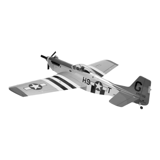
- Page 2 P-51 PTS Mustang Mk II Assembly Manual Speciications Wingspan: ............58.25 in (1480mm) Length: ..............50.4 in (1281mm) Wing Area: ..........626 sq in (40.38 sq dm) ..........648 sq in (41.81 sq dm) w/droops Weight: ............6.5–7 lb (2.9–3.2 kg) Radio: ............4-channel w/5 servos...
-
Page 3: Table Of Contents
Table of Contents Contents of Kit and Parts Layout ...........2 Using the Manual ..............3 UltraCote® Covering Colors ..........3 Before Starting Assembly ............3 Radio and Power Systems Requirements ......3 Field Equipment Required ............3 Optional Field Equipment ............3 Additional Required Tools and Adhesives ......3 Optional Tools and Adhesives for Flap Installation ....3 FS One ...................3 Important Information Regarding Warranty Information ..3... -
Page 4: Using The Manual
Using the Manual Radio and Power Optional Tools and Adhesives Systems Requirements for Flap Installation This manual is divided into sections to help make assembly easier to understand, and to provide breaks between each Spektrum Radio System major section. In addition, check boxes have been placed next to each step to keep track of each step completed. -
Page 5: Section 1: Charging Your Receiver Battery
Section 1: Step 3 Charging your Receiver Battery Connect the battery charger to the lead exiting the switch harness labeled CHARGE. Allow the charger to charge the battery for 10–12 hours before flying your model. Items required Before flying your P-51 Mustang PTS, you will need to charge the receiver battery for 12–14 hours prior to use. -
Page 6: Section 2: Installing The Landing Gear
Section 2: Step 2 Installing the Landing Gear landing gear straps using the screws. Tighten the landing Items Required gear straps until they pull the landing gear into the groove, flush with the bottom of the wing. Step 1 Locate the left landing gear strut. Slide the strut into position on the bottom of the wing. -
Page 7: Section 3: Installing The Tail Surfaces
Section 3: Step 2 Installing the Tail Surfaces Remove the clevises from the control horn. To remove the clevis, carefully slide the clevis retainer off of the clevis so it can be opened. Use a flat blade screwdriver to open the Items Required clevis and remove it from the control horn. - Page 8 Note: The fuselage fairing is not glued in place. Make Step 4 Step 5 sure to keep the fairing in position when installing the Slide the stabilizer/fin assembly back into position on the Thread the washers and nuts back on the rods. Tighten the stabilizer.
-
Page 9: Section 4: Installing The Propeller
Section 4: Step 2 Installing the Propeller Check to make sure the flywheel is properly positioned on the engine crankshaft. Slide the spinner backplate onto the engine shaft, and then slide the propeller into position. Items required -inch wood screw (4) Step 1 Remove the shipping protector, propeller nut and washer from the engine. - Page 10 Step 3 Step 4 Slide the washer and thread the nut onto the engine shaft. Rotate the propeller clockwise so it is resting against the screws. Position the spinner cone onto the spinner lugs of the spinner backplate. Use a 7/16-inch box end backplate, making sure it keys into the backplate.
-
Page 11: Section 5: Attaching The Wing
Section 5: Step 5 Attaching the Wing Items required Note: The exhaust stack for the right side of the model is shorter than the left. This is necessary to clear the muffler. Step 1 Locate the aluminum wing tube. Slide the wing tube into the wing tube socket in one of the wing panels. - Page 12 Step 2 Step 3 Locate the aileron Y-harness inside the fuselage. Make sure Slide the wing tube and wing panel into the socket in the one end of the harness exits the right side of the fuselage fuselage. Plug the lead for the aileron servo in the wing and one exits the left side of the fuselage.
-
Page 13: Section 6: Your Spektrum Dx6I Radio System
Section 6: Step 5 Step 6 Your Spektrum DX6i Radio System Use the screws and a 3/32-inch ball driver or hex wrench to You can now slide the remaining wing panel onto the wing secure the wing to the fuselage. If the screw does not go in tube. -
Page 14: Section 7: Transmitter Battery Installation
Optional Ni-Cd or Ni-MH 1.2 volt AA rechargeable batteries Section 7: (Spektrum 1500mAh Ni-MH AA (4 Pack) (SPM9525)) can Transmitter Battery Installation also be used. A charge jack is located on the left side of the transmitter for convenient recharging. You will need to Antenna Mode 1 Transmitter The DX6i transmitter requires 4 AA batteries:... -
Page 15: Section 8: Digital Trims
Section 8: Section 9: Low Battery Alarm Section 11: Digital Trims Binding When the battery voltage drops below 4.7 volts an alarm will sound and the voltage LEDs will flash. If flying you should The DX6i employs digital trim levers on aileron, elevator, Binding is the process of teaching the receiver the specific land immediately. - Page 16 Step 3 Step 4 Unplug the lead from the switch harness that connects to Plug the bind plug included with the radio system into the the battery/bind port of the receiver. Plug the lead from the battery/bind port of the receiver. switch harness into the aileron lead coming from the receiver at this time.
-
Page 17: Section 12: Mode 2 Vs Mode 1
Section 12: Step 6 Step 8 Mode 2 vs Mode 1 Establish the desired fail-safe stick positions: normally low Remove the bind plug from the receiver before turning off throttle and flight controls neutral. the receiver and store it in a convenient place. Turn off the Your P-51 Mustang PTS is offered with either a Mode 1 or receiver and transmitter to complete the procedure. -
Page 18: Section 13: Centering The Control Surfaces
Section 13: Centering the Control Surfaces Tools required How to remove the clevis from a control surface Aileron If may be necessary to remove the clevises from the control Trim horns to center the control surfaces. To remove the clevis, carefully slide the clevis retainer off of the clevis so it can be opened. - Page 19 Elevator Rudder Connect the elevator clevis to the outside hole on the Connect the rudder clevis to the center hole on the rudder elevator control horn. control horn. Elevator Trim Mode 1 Transmitter With the radio system on, check to be sure the elevator is With the radio system on, check to be sure the rudder is aligned to the stabilizer.
-
Page 20: Section 14: Checking The Control Surface Directions
LEFT AILERON Section 14: Checking the Control With the radio system still on, move the aileron control stick to the left, which is the input for a left turn. The left aileron Surface Directions will move up, and the right aileron will move down. If not, check the radio instructions on how to reverse the direction RIGHT AILERON electronically at the transmitter. - Page 21 UP ELEVATOR DOWN ELEVATOR RIGHT RUDDER With the radio system still on, pull back on the elevator With the radio system still on, push forward on the elevator The final control surface direction to check is the rudder. control stick to give an up elevator input. The elevator should control stick to give a down elevator input.
-
Page 22: Section 15: Checking The Control Throw Amounts
LEFT RUDDER AILERON LOW RATE Section 15: Checking the Control Throw Amounts Move the rudder control stick to the left, this will make the plane turn left. The rudder should deflect to the left as well. The Dual Rate switch allows for aileron, elevator and rudder If not, check the radio instructions on how to reverse the rates. -
Page 23: Section 16: Adjusting The Throttle
RUDDER HIGH RATE Note: If you can borrow a throw gauge that measures Section 16: in degrees, the amounts are: Adjusting the Throttle -inch (13mm) With the radio system on, move the trim lever and throttle control stick towards the bottom of the transmitter. Look into the carburetor to check that the barrel is closed. -
Page 24: Section 17: Balancing Your P-51 Pts
Section 17: Balancing Your P-51 PTS In order for your P-51 PTS Mustang to fly correctly, you will need to check the balance of the plane. This is done by supporting the aircraft either using your fingers, or by using a balancing stand. -
Page 25: Section 18: How To Range Test The Dx6I
Adding Weights to Correct the Balance Section 18: Due to manufacturing differences, it is possible that the How to Range Test the DX6i P-51 PTS Mustang may not be balanced properly. Weights can be added to either the tail or the nose of your P-51 PTS Before each flying session, and especially with a new Mustang if it does not balance properly. -
Page 26: Section 19: Flight Preparations
RANGE TESTING THE DX6I Section 19: Section 20: Flight Preparations Starting and Adjusting the Evolution Engine Step 1 Flight preparations must be checked each time you travel With the model resting on the ground, stand 30 paces to the flying field. Because the P-51 PTS Mustang will (approx. - Page 27 If your engine starts from the above procedure, but won’t STEP 2: LOW-SPEED NEEDLE ADJUSTMENT Step 4 reliably continue to run with the glow driver removed, follow Close the throttle to the idle position and have a helper hold The low-speed or idle needle valve, included with the the steps below.
-
Page 28: Section 21: Maintaining Your P-51 Pts Mustang
TROUBLESHOOTING GUIDE ENGINE MAINTENANCE Section 21: Maintaining Your P-51 PTS Mustang After each flying session: Engine Won’t Fire The following is a check list that you should follow Step 1 every time you have completed a flying session with your - Charge glow starter P-51 Mustang PTS. -
Page 29: Section 22: Progressing With Your Flying Skills
Checking the Control Horns Section 22: Inspect the control horns to make sure they have not Progressing With Your Flying Skills crushed the wood of the control surface. If so, remove the control horn screws to remove the control horn. Place 2–3 Required Tools and Adhesives drops of thin CA into each of the screw holes. - Page 30 Setting the Flap Position Initial Training Flap Settings Intermediate Setting To set the flap position, slide the clevis retainer off of the Setting the linkage to the forward hole of the stay sets the As you continue to advance, the flap linkage can again be clevis so it can be opened Use a flat blade screwdriver to flaps to the position for initial flight training.
-
Page 31: Section 23: Adding A Flap Servo
Once the flaps have been set, slide the clevis retainer onto Section 23: the clevis to keep the clevis from opening accidentally. Adding a Flap Servo Required Parts Required Tools and Adhesives Graduate Step 1 Once you are comfortable soloing your P-51 PTS Mustang in this configuration, you’re ready to graduate to advanced Slide the clevis retainer off of the clevis so it can be opened. - Page 32 Step 3 Step 4 Use a hobby knife to score the flap stay on both sides. You Turn on the radio and plug a Y-harness into the Aux1 port on only need to go across the stay a couple times to weaken it. the main receiver.
- Page 33 Step 6 Step 8 Step 10 Check that the edge of the servo horn is in line with the edge Use sandpaper to roughen the ends of the four servo Position the servo between the blocks. Leave a small gap of the servo cover.
- Page 34 Step 12 Step 14 Step 16 Apply 2–3 drops of thin CA into the holes to harden the Guide the flap servo lead out of the end of the wing. We surrounding wood. This provides a hard surface for the away any unused arms from the servo horn with side cutters.
- Page 35 Step 18 Step 19 Step 20 Insert the flap linkage into the outer hole you enlarged earlier. Attach the clevis to the flap control horn center hole. Plug With the radio system still on, position the flap switch to Rotate the linkage to face toward the flap control horn. the flap servo lead into the servo leads on the Y-harness.
-
Page 36: Safety Do's And Don'ts For Pilots
Safety Do’s and Don’ts for Pilots Daily Flight Checks Step 21 Once the flaps have been adjusted and the control throws set, slide the clevis retainer onto the clevis to keep the clevis prior to your initial flight. Step 1 from opening accidentally. -
Page 37: Glossary Of Terms
Pitch Axis: The horizontal plane on which the airplane’s Glossary of Terms Safety, Precautions and Warnings nose is raised or lowered. By moving the elevator, you can As the user of this product, you are solely responsible for raise the airplane’s nose above the pitch axis (climb) or Ailerons: Each side of this airplane has a hinged control operating it in a manner that does not endanger yourself lower it below the pitch axis (dive). -
Page 38: Warranty Information
Hangar 9 P51D Mustang Mk II RTF Описание...
Need help?
Do you have a question about the P-51 PTS Mustang Mk II and is the answer not in the manual?
Questions and answers