Table of Contents
Advertisement
Quick Links
Extron Electronics, USA
Extron Electronics, Europe
1230 South Lewis Street
Beeldschermweg 6C
Anaheim, CA 92805
3821 AH Amersfoort
USA
The Netherlands
714.491.1500
+31.33.453.4040
www.extron.com
Fax 714.491.1517
Fax +31.33.453.4050
© 2002 Extron Electronics. All rights reserved.
Extron Electronics, Asia
Extron Electronics, Japan
135 Joo Seng Road, #04-01
Daisan DMJ Building 6F
PM Industrial Building
3-9-1 Kudan Minami
Singapore 368363
Chiyoda-ku, Tokyo 102-0074 Japan
+65.6383.4400
+81.3.3511.7655
Fax +65.6383.4664
Fax +81.3.3511.7656
User's Manual
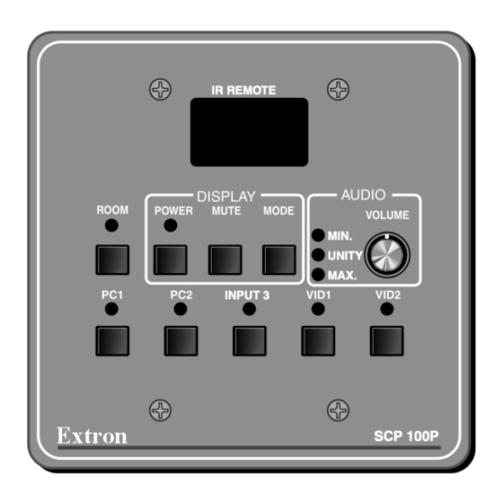
IR REMOTE
MIN.
UNITY
MAX.
INPUT 3
SCP 100P
SCP 100P
Control Panel
68-390-01
Printed in the USA
Advertisement
Table of Contents

Related Manuals for Extron electronics SCP 100P


Summary of Contents for Extron electronics SCP 100P
- Page 1 3821 AH Amersfoort PM Industrial Building 3-9-1 Kudan Minami 68-390-01 Singapore 368363 Chiyoda-ku, Tokyo 102-0074 Japan The Netherlands 714.491.1500 +31.33.453.4040 +65.6383.4400 +81.3.3511.7655 Printed in the USA www.extron.com Fax 714.491.1517 Fax +31.33.453.4050 Fax +65.6383.4664 Fax +81.3.3511.7656 © 2002 Extron Electronics. All rights reserved.
- Page 2 Instrucciones de seguridad • Español particular use. In no event will Extron Electronics be liable for direct, indirect, or Advertencia Este símbolo se utiliza para advertir al usuario sobre Alimentación eléctrica •...
-
Page 3: Table Of Contents
................. A-2 Accessories ................A-3 Panel Dimensions ..............A-3 Template ..................A-4 All trademarks mentioned in this manual are the properties of their respective owners. 68-390-01 Rev. C Printed in the USA 02 02 SCP 100P • Table of Contents... -
Page 4: Chapter 1 • Introduction And Installation
Table of Contents, cont’d SCP 100P Chapter One Introduction and Installation About the SCP 100P Installation Instructions SCP 100P • Table of Contents... -
Page 5: About The Scp 100P
Refer to the System 5 cr Plus User’s Manual (part #68-498-01) for details on installing and operating the switcher. The SCP 100P includes a 2-gang wall box, and it can be mounted in a wall, desk, or podium. The SCP 100P is available in three... -
Page 6: Rear Panel (Circuit Board) And Cabling
Introduction and Installation, cont’d Rear panel (circuit board) and cabling SCP 100P, and watching the LEDs on the switcher to see if the system switches to the desired inputs. The connections between the SCP 100P and the System 5 cr Plus can be tested even if input/output devices are not available. -
Page 7: Application Diagram
Introduction and Installation, cont’d Application diagram SCP 100P Below is an example of a typical installation of an SCP 100P control pad and a System 5cr Plus switcher. SYSTEM 5 Plus AUDIO PC1 INPUT DISPLAY ROOM AUDIO COMPUTER POWER MUTE... -
Page 8: Front Panel Features
Operation Operation, cont’d The SCP 100P replicates the front panel controls of the Display Power button and LED — Once the System 5cr Plus has System 5cr Plus. been programmed with the commands for the specific projector, pressing this button toggles the projector’s power The System 5 cr Plus cannot be configured from the on or off. -
Page 9: And Dimensions
Included Parts via the RS-232 control. While audio breakaway is active, on both the SCP 100P’s panel and the switcher’s Accessories front panel, the flashing LED indicates the input providing the audio signal, and the steadily lit LED indicates the active video input. -
Page 10: Specifications
MAX. 2.200 CLIP Included Parts 2.150 2.000 MIN. INPUT 3 VID1 VID2 RECT. These items are included in each order for an SCP 100P: 1.650 0.331 x 0.371 THRU PLACES) 1.300 Included parts Part number 0.609 SCP 100P (grey) 60-331-01... -
Page 11: Template
Template Use the template as a guide to mark and cut the hole in the wall or furniture through which the SCP 100P will be installed. The template includes the recommended 0.1” (0.25 cm) clearance on all sides of the electrical wall box to allow room for the raised areas surrounding the knockouts.
Need help?
Do you have a question about the SCP 100P and is the answer not in the manual?
Questions and answers