Motorola DCT6400 Series Installation Manual
High definition dual-tuner dvr cable receiver
Hide thumbs
Also See for DCT6400 Series:
- User manual (43 pages) ,
- User manual (40 pages) ,
- User manual (43 pages)
Table of Contents
Advertisement
Quick Links
Download this manual
See also:
User Manual
Advertisement
Table of Contents

Related Manuals for Motorola DCT6400 Series


Summary of Contents for Motorola DCT6400 Series
-
Page 1: Installation Manual
Installation Manual DCT6400 Series High Definition Dual-Tuner DVR Cable Receiver... - Page 2 CAUTION RISK OF ELECTRIC SHOCK CAUTION: TO REDUCE THE RISK OF ELECTRIC SHOCK, DO NOT REMOVE COVER (OR BACK). NO USER-SERVICEABLE PARTS INSIDE. REFER SERVICING TO QUALIFIED SERVICE PERSONNEL. Caution These servicing instructions are for use by qualified personnel only. To reduce the risk of electrical shock, do not perform any servicing other than that contained in the Installation and Troubleshooting Instructions unless you are qualified to do so.
- Page 3 Motorola, Inc. Motorola reserves the right to revise this publication and to make changes in content from time to time without obligation on the part of Motorola to provide notification of such revision or change. Motorola provides this guide without warranty of any kind, either implied or expressed, including, but not limited to, the implied warranties of merchantability and fitness for a particular purpose.
-
Page 4: Table Of Contents
Cabling to a Standard Definition TV and Audio Receiver ....................3-8 Installing the Optional IR Blaster ..............................3-9 Locating the IR Receiver on the VCR............................ 3-9 Connecting the IR Blaster ..............................3-10 Checking the IR Blaster................................ 3-10 DCT6400 Series Installation Manual... - Page 5 Memory Configuration ................................4-15 d10 Keypad - LED ...................................4-15 d11 Interface Status..................................4-16 d12 User Setting Status .................................4-18 d13 DVR/Hard Drive Status................................4-20 d14 Interactive Info..................................4-22 Section 5 Troubleshooting Appendix A Specifications Appendix B Connection Record Abbreviations and Acronyms DCT6400 Series Installation Manual...
- Page 6 Table 2-2 Rear panel connections..............................2-3 Table 3-1 LED displays and OOB frequencies ........................... 3-12 Table 3-2 Boot cycle error codes ..............................3-13 Table 3-3 Operational check ................................ 3-14 Table 3-4 Modes supporting graphics overlay........................... 3-17 DCT6400 Series Installation Manual...
-
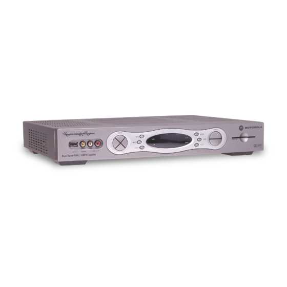
Page 7: Figure 1-1 Dct6400 Front And Rear Views
Ethernet and Universal Serial Bus (USB) ports for future home networking applications Adaptability to various software platforms As with all Motorola digital set-tops, the hardware features are enabled by core operating and third party application software. Figure 1-1... -
Page 8: Introduction
SWAP Record a program in the background while viewing another live program Simultaneously record programs from two channels while watching a different pre-recorded program, with the ability to switch viewing between any of the three programs DCT6400 Series Installation Manual... -
Page 9: Standard Data Features
Introduction Motorola cannot guarantee the exact amount of programming that each subscriber will be able to record. The approximate time depends on the programming type and the drive size: Table 1-1 DVR Recording Time Guidelines Estimated Recording Hours For Model... -
Page 10: Using This Manual
Acronyms Related Documentation The following documentation may be helpful when operating the DCT6400: DCT6400 Series User Guide User documentation for the remote control, audio receiver, TV, and other components Separate instruction manuals are available for associated components. Document Conventions... -
Page 11: If You Need Help
24 hours per day, 7 days per week. Calling for Repairs If repair is necessary, call the Motorola Repair Facility at 1-800-227-0450 for a Return for Service Authorization (RSA) number before sending the unit. The RSA number must be prominently displayed on all equipment cartons. -
Page 12: Overview
Section 2 Overview This section describes the DCT6400 series front and rear panel. Front Panel The front panel contains selection and tuning buttons, various displays, the power switch, and connectors for USB, audio and video. The front panel controls provide functional navigation of the DCT6400 if the remote control is lost or is temporarily out of service. -
Page 13: Rear Panel
Some connectors are not enabled and require the support of application software. Figure 2-2 Rear panel VIDEO ETHERNET SPDIF AUDIO IN IEEE 1394 DVI-D OUT S-VIDEO CABLE AUDIO OUT OPTICAL Pass Card SPDIF 12 13 14 15 DCT6400 Series Installation Manual... -
Page 14: Table 2-2 Rear Panel Connections
Optical digital output that carries Dolby Digital 5.1 audio or PCM audio. OPTICAL SPDIF IEEE 1394 IEEE 1394 connector for connecting to audio and video devices such as a DTV. * These connectors are not enabled and require the support of the application software. DCT6400 Series Installation Manual... -
Page 15: Installation
Do not block the slots, openings, and air vents on the set-top. Do not place anything on top of the set-top. Do not position the set-top in an enclosed entertainment center or cabinet that does not provide adequate ventilation. DCT6400 Series Installation Manual... -
Page 16: Before You Begin
If you correctly enter this key sequence in five seconds or less, the hard drive is cleared and the front-panel LED displays is not displayed, re-enter the key sequence in step 2 is displayed, press any other key to reset the set-top, turn it off, and complete the clearing process. DCT6400 Series Installation Manual... -
Page 17: Video Connection Options
DVD player, a secondary VCR, a CD player, or other electronic component. We recommend connecting the TV to the monitor output so on-screen menus for the receiver can be displayed. (In many cases the receivers themselves have interactive on-screen menus). DCT6400 Series Installation Manual... -
Page 18: Installation Overview
Perform the operational check for the remote control. Optimize the high-definition settings. See “Optimizing the High-Definition Settings” in this section. 10 Verify that the appropriate configuration information has been downloaded using the addressable controller, such as the DAC 6000. DCT6400 Series Installation Manual... -
Page 19: Cabling To An Hdtv For Video
Cabling to an HDTV DCT6400 VIDEO ETHERNET SPDIF AUDIO IN IEEE 1394 DVI-D OUT S-VIDEO CABLE AUDIO OUT OPTICAL Pass Card SPDIF Cable in either / or HDTV Component Video Input DVI-HDTV CABLE/ ANTENNA IN IEEE 1394 DCT6400 Series Installation Manual... -
Page 20: Cabling To An Hdtv And Audio/Video Receiver
SPDIF connections. Otherwise, do not connect both the baseband left/right RCA connections and the RCA SPDIF digital connection. The baseband connections are not necessary because the SPDIF port carries audio for both digital and analog channels providing for a single audio interface. DCT6400 Series Installation Manual... -
Page 21: Cabling To A Standard Definition Tv And Audio/Video Receiver
AUDIO RIGHT Because some entertainment equipment cannot simultaneously support baseband composite video and S-Video, never simultaneously connect both video inputs. This connection method does not support HDTV. For information, see “Cabling to an HDTV for Video.” DCT6400 Series Installation Manual... -
Page 22: Cabling To A Standard Definition Tv And Audio Receiver
OUTPUT COAX SPEAKER AUDIO IN CONNECTORS AUDIO VIDEO S-VIDEO AUDIO VIDEO S-VIDEO CABLE OPTICAL AUDIO OUT The video connections shown in this illustration do not support HDTV. For information, see “Cabling to an HDTV for Video.” DCT6400 Series Installation Manual... -
Page 23: Installing The Optional Ir Blaster
Because the IR Blaster radiates in an area approximately 40 degrees wide, you do not need to be precisely on target with the receiver. You may prefer to offset the location of the IR Blaster transmitter so that it is less likely to interfere with operation of the VCR remote control. DCT6400 Series Installation Manual... -
Page 24: Connecting The Ir Blaster
The IR Blaster is now located near the receiver and the VCR can be controlled through the set-top. As a final check, operate the VCR using the remote control from various positions in the room. If the IR Blaster is obstructing the IR receiver on the VCR, move it slightly. DCT6400 Series Installation Manual... -
Page 25: Data Device Connections
Can be used for electronic commerce. Card interface Figure 3-7 Sample data devices you can connect to the DCT6400 DCT6400 VIDEO ETHERNET SPDIF AUDIO IN IEEE 1394 DVI-D OUT S-VIDEO CABLE AUDIO OUT OPTICAL Pass Card SPDIF Home Ethernet Network devices DCT6400 Series Installation Manual... -
Page 26: Boot Cycle
If all the segments are retrieved in the first pass, the EF, AU and FP messages are displayed on the LED. If segments are dropped, the progress indicator appears to stall and then inch forward after the dropped segments are retired. DCT6400 Series Installation Manual... -
Page 27: Boot Cycle Error Codes
Reset within two minutes of a complete No action required software object download because the set-top repeats software object download process Eb 10 SUDB recreation After plugging the set-top into an electrical None outlet to begin the boot cycle DCT6400 Series Installation Manual... -
Page 28: Operational Check For The Remote Control
+ or - on the remote control to increase the volume to its upper limit, VOLUME lowest level, and to a comfortable level. Press to turn the sound off. Press again to restore the sound. MUTE MUTE If the set-top does not operate properly, refer to Section 5, “Troubleshooting”. DCT6400 Series Installation Manual... -
Page 29: Optimizing The High-Definition Settings
“There is no video on the TV screen” in Section 5, “Troubleshooting.” For a TV with a DVI connection, be sure the TV is on and connected to the set-top D OUT connector before adjusting the settings. DCT6400 Series Installation Manual... - Page 30 Selection Settings Sets the default settings for closed captions (AUTO) or the settings you have configured (USER). Defaults to AUTO. Options are AUTO or USER. Restore Defaults Resets the on-screen display options to their default settings. DCT6400 Series Installation Manual...
-
Page 31: Graphics Overlaying The Video
480i and the subscriber tunes to a 4:3 standard channel, the DCT6400 displays graphics overlays on all outputs even if the DVI or Y Pb Pr Output Mode is 1080i, 720p, or 480p. DCT6400 Series Installation Manual... -
Page 32: Diagnostics
All signal-level and quality indicators use a 1% to 100% scale, unless otherwise noted. All sample displays are illustrative; actual data may differ from the examples. You can use the diagnostics when running the base platform or Thin Client software. DCT6400 Series Installation Manual... -
Page 33: Using The Diagnostics
▲, or ▼ to select d01 through E. Press CHANNEL CHANNEL CURSOR CURSOR ◄, ►, Press to execute the selected diagnostic. CURSOR CURSOR SELECT ENTER Select E from the main menu or press to exit. POWER DCT6400 Series Installation Manual... -
Page 34: D01 General Status
The interface from the set-top to the subscriber TV; channel 3 or 4 in the USA. Settop Time The current OOB set-top time displayed in Global Positioning System (GPS) seconds from Jan 6, 1980. It is an integer from 0 to 4294967295. DCT6400 Series Installation Manual... -
Page 35: D02 Purchase Status
The last time the set-top attempted to report back purchases to the controller, in GPS seconds. IPPV Status If IPPV is enabled, the IPPV status indicator LED is on. If IPPV is disabled, the IPPV status indicator LED is off. DCT6400 Series Installation Manual... -
Page 36: D03 Out-Of-Band (Oob) Status
OOB data not detected within last 5 seconds EMM Data Indicates whether EMM data is being carried on the OOB stream: Description EMM data detected within last 5 seconds EMM data not detected within last 5 seconds DCT6400 Series Installation Manual... -
Page 37: D04 In-Band Status
32.0 dB GOOD AGC: FAIR 5 SECOND ERROR COUNTS: UNCORRECTABLE: 1234 CORRECTABLE: 5678 Figure 4-5 LED display for in-band diagnostic Data activity indicator MUTE MUTE IB diagnostic Carrier lock indicator indicator (L = locked, U = unlocked) DCT6400 Series Installation Manual... - Page 38 Counts It is updated every 5 seconds and reset each time the set-top is power cycled or another digital multiplex is tuned. The maximum value displayed is 9999, even if there were more than 9999 errors. DCT6400 Series Installation Manual...
-
Page 39: D05 Unit Address
1394: xx xx xx xx xx xx USB: xx xx xx xx xx xx Settop: xx xx xx xx xx xx Figure 4-6 LED display of a unit address MUTE MUTE MUTE MUTE MUTE DCT6400 Series Installation Manual... - Page 40 Messages not matching the multicast address are discarded. MAC Addresses The DOCSIS, Ethernet, 1394, USB, and set-top MAC addresses are stored in protected flash and displayed in hexadecimal format. DCT6400 Series Installation Manual...
-
Page 41: D06 Current Channel Status
MPEG AUDIO LOCK PCR LOCK Figure 4-7 Current channel status LED displays Preview indicator Analog channel: Purchasable indicator MUTE MUTE Analog channel indicator Preview indicator Digital channel: Purchasable indicator MUTE MUTE Digital channel indicator Epoch authorization code DCT6400 Series Installation Manual... - Page 42 Indicates whether the audio processor is locked to the audio stream: Lock YES — locked NO — not locked PCR Lock Indicates whether the in-band receiver is locked to the program clock reference (PCR): YES — locked NO — not locked DCT6400 Series Installation Manual...
-
Page 43: D07 Rf Modem (Upstream)
The power level is displayed on the OSD and LED in dB or is blank if the power level has not Level been set. Report Back Displayed in 4-byte hexadecimal format, if configured. Address Last RB The last attempted report back by the set-top, in GPS seconds. Attempt Time DCT6400 Series Installation Manual... -
Page 44: D08 Code Modules
MUTE MUTE MUTE MUTE Code module identifier (bPC for the base platform; CODE or SYS for the system object) MUTE MUTE Alternating with Code module version number MUTE MUTE Indicator separating major and minor revision numbers DCT6400 Series Installation Manual... - Page 45 Connected to download PID − awaiting CONNECTED Connect data PEND CONNECT TryingToConnect Trying to connect Segs/Time Indicates the segments remaining in the download or the total time of the completed download in GPS seconds, displayed on the OSD and LED. DCT6400 Series Installation Manual...
-
Page 46: D09 Memory Configuration
The allocated flash memory in MB. NVRAM The allocated NVRAM in KB. d10 Keypad - LED This diagnostic verifies the functionality of the LEDs and the front-panel keypad. Each highlighted character corresponds with a front-panel key press. < > Î DCT6400 Series Installation Manual... -
Page 47: D11 Interface Status
USB I/O Device INST (installed) or NOT INST (not installed) 10BT Ethernet Device INST (installed) or NOT INST (not installed) Parallel Port INST (installed) or NOT INST (not installed) IR Blaster INST (installed) or NOT INST (not installed) DCT6400 Series Installation Manual... - Page 48 EDID Data is blank. An asterisk (*) after the aspect ratio means the set-top supports the format. If more than twelve video timing formats are discovered, the supported formats only are listed first followed by any remaining formats, up to twelve. DCT6400 Series Installation Manual...
-
Page 49: D12 User Setting Status
If this occurs, view the settings on the LED panel to change the format back to 480i. If you are not using the DVI video connection, the DVI/YPbPr OUTPUT setting displays as YPbPr OUTPUT. DCT6400 Series Installation Manual... - Page 50 Displays the selected setting: AUTO — Closed caption settings are determined by the closed caption stream regardless of user modification. USER — The configured closed caption user settings are used. Restore Defaults Resets the user settings to their defaults. DCT6400 Series Installation Manual...
-
Page 51: D13 Dvr/Hard Drive Status
LOW1 — 1 Mbps LOW2 — 2 Mbps MEDIUM1 — 3 Mbps MEDIUM2 — 4 Mbps HIGH1 — 5 Mbps HIGH2 — 6 Mbps NOT AVAILABLE — the encoder is not enabled or configured DCT6400 Series Installation Manual... - Page 52 Active any time disc access is necessary). Active — The hard drive is accessing data. Failed — The hard drive hardware has failed. Temp (F) For an internal hard drive only, its temperature in degrees F. DCT6400 Series Installation Manual...
-
Page 53: D14 Interactive Info
00000000 is displayed when the UPM is not configured or unknown. Upstream ID A four-digit decimal value from 0000 to 9999 assigned by the DAC 6000 to the set-top. 0000 is displayed if the Upstream ID is not configured or unknown. DCT6400 Series Installation Manual... - Page 54 READY — The socket is ready to send or receive. RECEIVING — The socket is receiving data from the application server. SENDING — The socket is sending data to the application server. UNKNOWN — The socket state is invalid or unknown. DCT6400 Series Installation Manual...
-
Page 55: Troubleshooting
Verify that the home theater receiver is set to a surround sound audio mode ® (Dolby Digital, Dolby Pro Logic , or Dolby Pro Logic II. Verify that the receiver is properly configured to work with all connected speakers. DCT6400 Series Installation Manual... - Page 56 Not all HDTVs can display every output format (1080i, 720p, 480p, or 480i) available on the DCT6400 Series. To select a different format: Ensure that your set-top is plugged into a power outlet and is turned off.
- Page 57 You may be able to minimize the border using the zoom feature on the TV. The DCT6400 series provides an internal fan to cool the integrated hard drive. There is a humming During normal operation, the fan emits a low humming noise, similar to a noise.
-
Page 58: Specifications
105 to 125, 60 Hz ac voltage 40 W nominal at 115 Vac Power dissipation 17.13 in. × 12.75 in. × 2.75 in. Size 11.5 pounds Weight DCT6408: 80 MB Hard Disk DCT6412: 120 MB DCT6416: 160 MB DCT6400 Series Installation Manual... -
Page 59: Figure B-1 Connection Record
S-VIDEO COAX OPTICAL CABLE/TV VIDEO 2 TV/MONITOR SPEAKER OUTPUT CONNECTORS VIDEO S-VIDEO Before connecting or changing cable connections, disconnect the power from the set-top. Do not place another component or object on top of the set-top. DCT6400 Series Installation Manual... - Page 60 Pay-Per-View Quadrature Amplitude Modulation QPSK Quadrature Phase Shift Keying Return for Service Authorization standard definition signal-to-noise ratio S/PDIF Sony Philips Digital Interface Format TCP/IP Transmission Control Protocol/Internet Protocol Technical Response Center DCT6400 Series Installation Manual...
- Page 61 Abbreviations and Acronyms-2 TvPC TV PassCard Universal Serial Bus video on demand Y Pb Pr component video connectors DCT6400 Series Installation Manual...
- Page 62 Visit our website at: www.motorola.com 512660-001 5/04 MGBI...
Need help?
Do you have a question about the DCT6400 Series and is the answer not in the manual?
Questions and answers