Table of Contents
Advertisement
Quick Links
Warranty
All products manufactured by ICP DAS are under warranty regarding
defective materials for a period of one year, beginning from the date of
delivery to the original purchaser.
Warning
ICP DAS assumes no liability for any damage resulting from the use of
this product. ICP DAS reserves the right to change this manual at any
time without notice. The information furnished by ICP DAS is believed to
be accurate and reliable. However, no responsibility is assumed by ICP
DAS for its use, nor for any infringements of patents or other rights of
third parties resulting from its use.
Copyright
Copyright © 2013 by ICP DAS. All rights are reserved.
Trademarks
Names are used for identification purpose only and may be registered
trademarks of their respective companies.
Technology Support
If you have any problems, please feel free to contact us via
email at
ICP DAS, ZT‐USB Series User Manual, Version 1.0
Copyright @ 2013 by ICP DAS Co., Ltd. All Rights Reserved.
ZT-USB Series
service@icpdas.com
User Manual
Page 1
Advertisement
Table of Contents

Related Manuals for ICP DAS USA ZT-USBC


Summary of Contents for ICP DAS USA ZT-USBC
-
Page 1: User Manual
ZT-USB Series User Manual Warranty All products manufactured by ICP DAS are under warranty regarding defective materials for a period of one year, beginning from the date of delivery to the original purchaser. Warning ICP DAS assumes no liability for any damage resulting from the use of this product. -
Page 2: Table Of Contents
Table of Contents 1 Introduction to ZigBee ....... 4 2 Introduction to the ZT‐USB Series ....5 3 Hardware Information ......... 6 3.1 Specifications ........6 3.2 ZT‐USB Series Front View ......7 3.3 Dimensions (Units: mm) ........ 8 3.4 Block Diagram ......... 9 4 Installing Driver and Utility ....... 10 4.1 Installing the ZT‐USB Serial Port Driver ..... 10 4.2 Inserting the ZT‐USB and installing Driver ... 13 4.3 Installing the Configuration Tool ....17 5 Setting up the ZT‐USB Series ...... - Page 3 What’s in the shipping package? The shipping package includes the following items: ZT‐USB Series CD Quick Start If any of these items are missing or damaged, please contact your local distributor for more information. Save the shipping materials and cartons in case you want to ship the module ...
-
Page 4: Introduction To Zigbee
Introduction to ZigBee ZigBee is a specification for a suite of high-level communication protocols using small, low-power digital radios based on the IEEE 802.15.4 standard for personal area networks. ZigBee devices are often used in mesh network form to transmit data over longer distances, passing data through intermediate devices to reach more distant ones. -
Page 5: Introduction To The Zt-Usb Series
(ZigBee Pro) of ZigBee Alliance. In the ZigBee network, it is only allowed one ZigBee Host and called “ZigBee Coordinator”, ZT-USBC is used to initialize and manager the routing. In addition, One ZigBee network are able to manager 255 ZigBee router and responsible for receiving or bypassing data from parent or child node. -
Page 6: Hardware Information
Hardware Information 3.1 Specifications Part Number ZT-USBC (Coordinator) ZT-USBR (Router) Hardware MCU Module 8-bit microprocessor Temporary Buffer Size 237 Bytes ZigBee Net Communication Interface Connector Type-A Plug Compatibility USB 1.1 and 2.0 standard Driver Windows 2000/XP/Vista/7/8 Power Required Supply Voltage USB Socket Powered Power Consumption 0.3 W(Max.) -
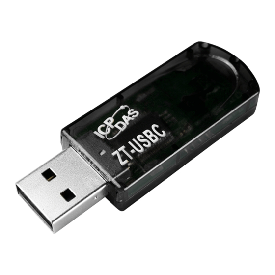
Page 7: Zt-Usb Series Front View
ZT‐USB Series Front View LED Indicator (ZigBee Net Status) USB Type-A Plug 2.4 GHz PCB Antenna 1. LED Indicator LED Indicator LED Color Explanation ZigBee Net The status of ZigBee network. For more details, please see the section 6 troubleshooting. ※ 2. USB Type-A Plug The port is used to configure ZT-USB series, communicate with other ZT-2000 modules and be powered via the USB socket. -
Page 8: Dimensions (Units: Mm)
Dimensions (Units: mm) Left Side View Front View Top View Page 8 ICP DAS, ZT‐USB Series User Manual, Version 1.0 Copyright @ 2013 by ICP DAS Co., Ltd. All Rights Reserved. ... -
Page 9: Block Diagram
Block Diagram LED Display USB ZigBee Module (Type A) Power Circuit Page 9 ICP DAS, ZT‐USB Series User Manual, Version 1.0 Copyright @ 2013 by ICP DAS Co., Ltd. All Rights Reserved. ... -
Page 10: Installing Driver And Utility
Installing Driver and Utility 4.1 Installing the ZT‐USB Serial Port Driver Download the file from website http://ftp.icpdas.com/pub/cd/usbcd/napdos/zigbee/zt_series/driver/ or from the CD in the shipping package CD: \Napdos\ZigBee\ZT_Series\driver the ZT-USB_Series_Driver_Installer.exe file and select the item that Right click to install the driver for the ZT-USB Series. Run as adminstrator When the following screen is displayed, click the button to continue. - Page 11 hen the following screen is displayed, click the button to continue. Install When the following screen is displayed, click the button to continue. Next> If the following screen is displayed, click the Always trust software from “ICP and press button to continue. DAS Co., LTD.”>...
- Page 12 When the following screen is displayed, click the Finish button to continue. When the following screen is displayed, click the Finish button to completing the installation. Page 12 ICP DAS, ZT‐USB Series User Manual, Version 1.0 Copyright @ 2013 by ICP DAS Co., Ltd. All Rights Reserved. ...
-
Page 13: Inserting The Zt-Usb And Installing Driver
Inserting the ZT‐USB and installing Drive r 1. Insert the ZT-USB series to USB socket in your computer. If Windows detects the new device, it will install the driver automatically and successfully. USB ZT‐USB Series 2. Right click on and select Properties. My Computer 3. Select from the dialog box. - Page 14 onfirm the of the ZT-USB Series is listed in the COM Number Ports(COM & LPT). 5. If Windows Ports(COM & LPT) is failed to allocate the COM Port Number of ZT-USB Series, you should find item below USB Serial Port Other ...
- Page 15 6. When the following screen is displayed, select the “Browse my computer for Option to continue. driver software” 7. Browse to to locate the install tion file, and click C:\\ICPDAS\ZT‐USB\driver\ and the button to begin the search. “Include subfolders” Next Page 15 ICP DAS, ZT‐USB Series User Manual, Version 1.0 Copyright @ 2013 by ICP DAS Co., Ltd. All Rights Reserved. ...
- Page 16 8. When the following screen is displayed, click the button to finalize the Close software installation. NOTICE: When the driver installation is complete, unplug ZT‐USB Series and insert it in again. Now you can find out the correct of ZT-USB series in the COM Port Number Device Manager.
-
Page 17: Installing The Configuration Tool
Installing the Configuration Tool Download the file from the website http://ftp.icpdas.com/pub/cd/usbcd/napdos/zigbee/zt_series/utility/ or from the CD in the shipping package CD: \Napdos\ZigBee\ZT_Series\utility Double click the file to install the ZT2000_Configuration_Utility_vxxx.exe configuration tool for the ZT-USB series. When the following screen is displayed, you can click the button to install Next>... - Page 18 hen the following screen is displayed, click the button to c ontinue. Next> When the following sc reen is displayed, click the button to finalize the Finish software installation. Page 18 ICP DAS, ZT‐USB Series User Manual, Version 1.0 Copyright @ 2013 by ICP DAS Co., Ltd. All Rights Reserved. ...
-
Page 19: Setting Up The Zt-Usb Series
Setting up the ZT‐USB Series 5.1 Introduction of configurations 1. “Pan ID” is the group identity of a ZigBee network, and must be the same if they are in the same ZigBee network. (Valid values range from 0x0000 to 0x3FFF) 2. “Node ID” is the identity of the ZigBee module. The identity number must be unique if it is in the same ZigBee network as other ZigBee module. - Page 20 4. “RF Power” denotes the wireless transmit power value. Code Note 0x0F Typical Maximum (Default) 0x00 Typical Minimum 5. Baud rate & Data Format” serial port settings are supported “ by ZT-USB Series. Item Specification Parity None(Default), Odd, Even Data Bit Stop Bit Baud rate 2400, 4800, 9600, 19200, 38400, 57600, 76800 and 115200(Default)
- Page 21 Communication Speed (The Interval Time of Sending B roadcast Frame): The d ata payload of ZT-2000 and ZT-USB series modules is 79 bytes. Once the data i s more than 79 bytes, it will be divi ded into several packets. This parameter is use d to d ecide the interval t...
- Page 22 ZT-USBR Unicast Data will only be sent to the coordinator [Eg1] When ZT-USBC (ZigBee Host) sends “DATA_01” via broadcasting frame, → Both of the ZigBee slave 0x0001 and 0x0002 will receive the “DATA_01”. ※Broadcasting type frame, data will be sent to every ZigBee slaves in the same ZigBee network [Eg2] When the ZT-USBR (ZigBee slave) 0x0001 sends “DATA_02”...
-
Page 23: Configuring Zigbee Setting
Configuring ZigBee Setting Launch the “ZT Configuration Utility” and click the [ZT Series] button. . Click the [Serial Port] icon and then select the COM Port number. 1 2 After selecting the COM Port number, a list of model numbers will be displayed. - Page 24 4. Choose serial baud rate and data format. The default setting is 115200bps and N,8,1. 5. Once a connection is established, select either the [Default] or the [Wizard] function from the settings mode page. Wizard Default 6. Whether you select either the [Default] or the [Wizard] option for performing configuration, both are used to configure the Pan ID, Node ID, RF Channel, Power, Baud rate, Data Format, Application Mode and so the relevant parameters.
- Page 25 7. Setting Pan ID/Node ID/RF Channel. For more details, please see section 4.1. 8. Baud Rate and Data Format 9. Once the module configuration has been completed, the message “The Configuration was successful” will be displayed. Page 25 ICP DAS, ZT‐USB Series User Manual, Version 1.0 Copyright @ 2013 by ICP DAS Co., Ltd. All Rights Reserved. ...
-
Page 26: Test Communications
5.3 Test Communications Method (1) Connect both the ZT-USBC and ZT-USBR to the Host PC via the USB ports. You may need to use two serial port tools to simulate the data transmission. Serial Tool Serial Tool USB USB ZT‐USBC ZT‐USBR Method (2):... -
Page 27: Applications
Applications e are dedicated to develop ZT-USB series in smart energy, home automa tion, health care and any other I/O nodes in low data rate communication. (1) ZT-USB series are able to be integrated into SCADA easily. If you choose ICP DAS ZT-2000, you can implement monitoring and controlling right away. -
Page 28: Troubleshooting
Troubleshootin g Technical Support If you have any difficulties using your ZT-USB series mod ule, please send a description of the problem to service@icpdas.com. Please the following items, A description to the communication protocol for more information. A copy of the configuration file for the ZT-USB Series module. This file can be obtained using the procedure outlined below and should be attached to your email. -
Page 29: Led Indicator Status
LED Indicator Status LED Indicator Status Introduction ZigBee Coordinator (Host) Steady Lit ZigBee network is Establish Blink to Steady Lit Rejoin ZigBee Network or It has Occupied ZigBe e Net ZigBee Router (Slave) (Red LED) Steady Lit The Signal is Strong Blinking (500 ms) The Signal is Available Blinking (1s) The Signal is Weak...
Need help?
Do you have a question about the ZT-USBC and is the answer not in the manual?
Questions and answers