Table of Contents
Advertisement
The 7000 Series Bus Converter
Warranty
All products manufactured by ICP DAS are under warranty regarding defective
materials for a period of one year from the date of delivery to the original purchaser.
Warning
ICP DAS assumes no liability for damages resulting from the use of this product.
ICP DAS reserves the right to change this manual at any time without notice. The
information furnished by ICP DAS is believed to be accurate and reliable. However, no
responsibility is assumed by ICP DAS for its use, or for any infringements of patents or
other rights of third parties resulting from its use.
Copyright
Copyright 1997 by ICP DAS. All rights are reserved.
Trademark
The names used for identification only may be registered trademarks of their
respective companies.
Revision History
Revision
1.5
1.6
1.7
1.8
7000 Bus Converter User's Manual (Version 1.8 Jan/2006, 7PH-006-18) --------------- 1
User's Manual
Data
2004/06/07
2005/02/25
2005/05/15
2006/01/18
Summary of changed
1. Add the jumper setting for I-7520A on page 14
2. Add the jumper setting for I-7520AR on page 16
1. Add the RS-232's jumper setting for I-7561 on
page 37
2. Modified the jumper setting for I-7520A/ I-7520A
on page 14/16
Add the PLUG AND PLAY description for I-7561
on page 37
for I-7551 on page 58
Correct Jumper setting
Advertisement
Table of Contents

Related Manuals for ICP DAS USA 7000 Series


Summary of Contents for ICP DAS USA 7000 Series
- Page 1 The 7000 Series Bus Converter User’s Manual Warranty All products manufactured by ICP DAS are under warranty regarding defective materials for a period of one year from the date of delivery to the original purchaser. Warning ICP DAS assumes no liability for damages resulting from the use of this product.
-
Page 2: Table Of Contents
The 7000 series overview..............4 Related Documentation for the 7000 Series ........5 Common Features of the 7000 Series..........6 The 7000 Series System Network for Bus Type ......... 7 7000 Dimension.................. 9 I-7520/A/R/AR, PCISA-7520AR, PCISA-7520R..........11 I-7520: ....................11 2.1.1... - Page 3 3.2.4 I-7561 Driver Installation ..............38 3.2.5 Verifying the Installation: ..............42 3.2.6 Uninstalling the Device Driver............45 I-7563 Pin Assignment and Specifications:........46 3.3.1 The I-7563 System Network Configuration: ........47 3.3.2 The I-7563 Block Diagram: ............. 47 3.3.3 I-7563 Driver Installation ..............
-
Page 4: Introduction
MMI and other functions. These modules can be controlled remotely by a set of commands. The 7000 series overview The 7000 series can be divided into several groups based on their function as follows: Group 1: bus converter modules, support bus converter & repeater 7520/7520R/ISA-7520R/PCISA-7520R: RS-232 to RS-485 converter, 3000V isolation. -
Page 5: Related Documentation For The 7000 Series
ACE-540A: 24V/2A power supply DIN-540A: ACE-540A with DIN-RAIL mount PWR-24/220V: 220V AC input, 24V/0.1A output power adapter PWR-24/110V: 110V AC input, 24V/0.1A output power adapter 1.2 Related Documentation for the 7000 Series • 7000 Bus Converter User Manual: For 7510/7520/7520A/7520R/7561/7510A/7520AR/ISA-7520A/ PCI-7520AR/PCISA-7520R •... -
Page 6: Common Features Of The 7000 Series
• Connecting 256*8=2048 modules max. In one RS-485 bus with repeater. • 7000 series data format=1 start + 8 data + 1 stop + no parity = 10-bit • Two extra checksum bytes can be enable/disable • Built-in transient voltage suppresser and PTC protector •... -
Page 7: The 7000 Series System Network For Bus Type
The 7000 Series System Network for Bus Type • Multiple Baud Rate • Multiple Data Format 7000 Bus Converter User’s Manual (Version 1.8 Jan/2006, 7PH-006-18) --------------- 7... - Page 8 In other words, the performance of the entire system must be decreased. The 7000 Series RS-485 Network: The 7000 RS-485 network is the most powerful and flexible two-wire RS-485 networks in the world. It is a multiple baud rate and multiple data format network system.
-
Page 9: 7000 Dimension
7000 Dimension 29.50 O4.5X4 56.00 2-SCREW 25.00 33.00 40.50 Back View 72.00 Side View Top View 50.00 56.00 58.50 72.00 From View 7000 Bus Converter User’s Manual (Version 1.8 Jan/2006, 7PH-006-18) --------------- 9... - Page 10 Stack Mounting Din – Rail Mounting 7000 Bus Converter User’s Manual (Version 1.8 Jan/2006, 7PH-006-18) --------------- 10...
-
Page 11: I-7520/A/R/Ar, Pcisa-7520Ar, Pcisa-7520R
I-7520/A/R/AR, PCISA-7520AR, PCISA-7520R 2.1 I-7520: 2.1.1 Pin Assignment and Specifications: 7520: RS-232 to RS-485 Converter • Protocol: Differential 2-wire half-duplex RS-485 • Connector: plug-in screw terminal block • Speed: “Self Tuner” inside, auto switching baud rate, from 300 to 115200 bps •... -
Page 12: Pin Assignment And Specifications
2.2 I-7520R: 2.2.1 Pin Assignment and Specifications: 7520R: RS-232 to RS-485 Converter • Protocol: two-wire RS-485, (D+, D-), protocol • Connector: plug-in screw terminal block • Speed: “Self Tuner” inside, auto switching baud rate, from 300 to 115200 BPS • 256 modules max in one RS-485 network without repeater •... -
Page 13: Pin Assignment And Specifications
2.3 I-7520A: 2.3.1 Pin Assignment and Specifications: 7520A: RS-232 to RS-422/485 Converter • Protocol: RS-422/485 • Connector: plug-in screw terminal block • Speed: “Self Tuner” inside, auto switching baud rate, from 300 to 115200 BPS • 256 modules max in one RS-485 network without repeater •... -
Page 14: The I-7520A Has Three Different Output Types
2.3.3 The I-7520A has three different output types Selecting the I-7520A output type. NOTE: The RS-422 and RS-485 output types couldn’t be used simultaneously, which means that you can only select 1 type to output. Type 1: 1-channel RS-485 output. Type 2: 1-channel RS-422 output. -
Page 15: I-7520Ar
I-7520AR : 2.4.1 Pin Assignment and Specifications: 7520AR: RS-232 to RS-422/485 Converter • Protocol: RS-422/485 • Connector: plug-in screw terminal block • Speed: “Self Tuner” inside, auto switching baud rate, from 300 to 115200 BPS • 256 modules max in one RS-485 network without repeater •... -
Page 16: The I-7520Ar Has Three Different Output Types
2.4.3 The I-7520AR has three different output types Selecting the I-7520AR output type. NOTE: The RS-422 and RS-485 output types couldn’t be used simultaneously, which means that you can only select 1 type to output. Type 1: 1-channel RS-485 output. Type 2: 1-channel RS-422 output. -
Page 17: Pcisa-7520Ar Pin Assignment And Specification
2.5 PCISA-7520AR Pin Assignment and Specification: DB9M FEMALE DB9S MALE DB9S MALE RS-485 ( D+, D- ) RS-422 ( RX+, RX-, TX+, TX- ) CON2: RS-485/422 DB9 Male Connector Terminal 2-wire RS-485 4-wire RS-422 DATA+ Not Connect Not Connect DATA- Not Connect The PCISA-7520AR is exactly the same as 7520AR except for the PCI and ISA interface. -
Page 18: Pcisa-7520R Pin Assignment And Specification
2.6 PCISA-7520R Pin Assignment and Specification: DB9M FEMALE DB9S MALE RS-485 ( D+, D- ) CON2: RS-485 DB9 Male Connector Terminal 2-wire RS-485 DATA+ Not Connect DATA- Not Connect The PCISA-7520R is exactly the same as 7520R except for the PCI and ISA interface. -
Page 19: Basic Wire Connection For I-7520
2.7 Basic Wire Connection for I-7520: RS 485 wire connection. Ext. Power GND Ext. Power 10V-30V Data- Data- Data- Data+ Data+ Data+ Init* RS 232 wire connection Host pin2 (RXD) 7520_Pin2 Host pin3 (TXD) 7520_Pin3 Host pin5 (GND) 7520_Pin5 7000 Host Computer 7520 7520R... -
Page 20: How To Select 7520 / 7520R
2.8 How to select 7520 / 7520R The 7520R is exactly the same as 7520 except for the isolation site. The isolation site of the 7520 is located in the RS-232 interface circuit, but the isolation site of the 7520R is located in the RS-485 interface circuit. - Page 21 Note: the power ground of 7000 common RS-485 is ground. This is the same for Adam 4000, Nudam 6000 and DATAFORTH 9B series modules. In most applications, the 7520 are used to convert the RS-232 signal to RS-485 network. Normally the 7520 does not use the same DC power ground as the Host PC/PLC, and the isolation site is in the RS-232 section.
- Page 22 Host PC/PLC will be isolated from RS-485 network in all conditions. The power adapter PWR-24 is designed for single 7000 series modules only. The 24V DC output of the PWR-24 is isolated from its AC input. If the 7520 or 7520R is connected to the PWR-24, this PWR-24 cannot connect to the other module.
- Page 23 The 7520R is designed for PLC networking. During normal conditions, the PLC system will have a stable DC-24V power source. The user may use this power source to 7520R(configuration A). When using 7520, the user must use another power source, PWR-24 (configuration B).
-
Page 24: Usb Series: I-7560 / I-7561 / I-7563
3. USB series: I-7560 / I-7561 / I-7563 What is USB? USB, or Universal Serial Bus is a connectivity specification developed by computer and telecommunication industry members for attaching peripherals to computers. USB is designed to free all the troubles when installing external peripherals. -
Page 25: I-7560 Pin Assignment And Specifications
3.1 I-7560 Pin Assignment and Specifications: Introduction The I-7560 adds a Windows serial Com port via its USB connection and is compatible with new & legacy RS-232 devices. USB Plug and Play allows easy serial port expansion and requires no IRQ, DMA, or I/O port resources. -
Page 26: The I-7560 System Network Configuration
3.1.1 The I-7560 System Network Configuration: 3.1.2 Block Diagram: 7000 Bus Converter User’s Manual (Version 1.8 Jan/2006, 7PH-006-18) --------------- 26... -
Page 27: I-7560 Driver Installation
3.1.3 I-7560 Driver Installation Installing the Device This section will guide you on how to install the I-7560 USB to RS-232 converter under Windows XP, Windows 2000, Windows ME, and Windows 98 operating systems. (No support for WinNT). Download driver files from 1. - Page 28 4. An “Install Hardware Device Drivers” window is shown. Click “Next” to initiate a search for a suitable driver for your device. 5. Select the “Specify a location” optional search locations. If the “CD-ROM drives” checkbox is selected, please insert the driver CD. Click “Next”...
- Page 29 6. If the “Specify a location” is selected, you much choose the correct path. Enter E:\Napdos\7000\756x\7560(The ‘E’ is the Disk that Package CD put in). Click “OK” to start the search. 7. Once Windows finds the correct driver, click “Next” to install the driver. 7000 Bus Converter User’s Manual (Version 1.8 Jan/2006, 7PH-006-18) --------------- 29...
- Page 30 8. Windows will then install the driver for the USB-to-Serial COM Port. Once installation is complete, Windows will notify you that it has finished installing the software. Click “Finish” to continue. NOTE: When you finish the driver installation, please unplug the USB cable, and then plug the USB cable again 7000 Bus Converter User’s Manual (Version 1.8 Jan/2006, 7PH-006-18) --------------- 30...
-
Page 31: Verifying The Installation
3.1.4 Verifying the Installation: This section will show you on how to verify whether the I-7560 was properly installed. You will also need to determine the COM port assignment made by Windows for the USB to RS-232 converter. Note: Before you connect the I-7560 for the first time, ensure that you do not attach any serial devices to the converter. - Page 32 2. If you need to reassign the COM Port name to another Port number, you can double-click on the device (I-7560 USB-to-RS232) to view the properties. (The I-7561 cannot reassign the COM Port name to another Port number under Win98 and Win98SE.) 3.
- Page 33 4. The Advanced Settings dialog box will now be displayed. Click on the COM Port Number drop down box to check what other port numbers are available. If, for instance, Windows has assigned COM5 to the device, you may try to reassign it to a lower unused port number. Click OK when finished.
-
Page 34: Uninstalling The Device Driver
3.1.5 Uninstalling the Device Driver It is easy to uninstall the USB to Serial device driver: 1. Run the DRemover98_2K.exe Uninstall program which can be found on the Package CD, \Napdos\7000\756x\7560 or at ftp://ftp.icpdas.com/pub/cd/8000cd/napdos/7000/756x/7560 2. The uninstall program will then prompt you whether you want to remove the utility program. -
Page 35: I-7561 Pin Assignment And Specifications
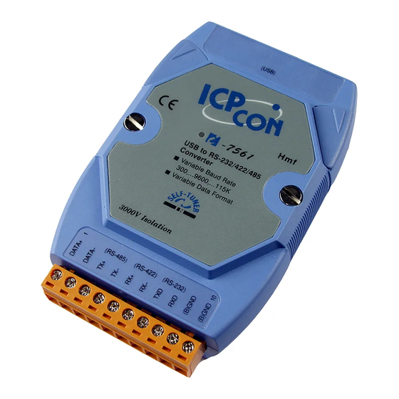
3.2 I-7561 Pin Assignment and Specifications Introduction The I-7561 is a cost-effective module for transfer serial data over USB. It allows you to connect your serial devices to systems using a USB interface. Connecting the I-7561 to a PC, you get one extra high-speed RS-232/422/485 ports. -
Page 36: The I-7561 System Network Configuration
3.2.1 The I-7561 System Network Configuration: • Multiple Baud Rate • Multiple Data Format 3.2.2 The I-7561 Block Diagram: 7000 Bus Converter User’s Manual (Version 1.8 Jan/2006, 7PH-006-18) --------------- 36... - Page 37 3.2.3 I-7561 has four different output types. Selecting the I-7561 output type. NOTE: The RS-232, RS-422 and RS-485 output types couldn’t be used simultaneously, which means that you can only select 1 type to output. Type 1: 1-channel RS-485 output. Type 2: 1-channel RS-422 output.
-
Page 38: I-7561 Driver Installation
3.2.4 I-7561 Driver Installation Installing the Device This section will guide you on how to install the I-7561 USB to RS-232/422/485 converter under Windows XP, Windows 2000, Windows ME, and Windows 98 operating systems. (No support for WinNT). Download driver files from 1. - Page 39 4. An “Install Hardware Device Drivers” window is shown. Click “Next” to initiate a search for a suitable driver for your device. 5. Select the “Specify a location” optional search locations. If the “CD-ROM drives” checkbox is selected, please insert the driver CD. Click “Next”...
- Page 40 6. If the “Specify a location” is selected, you much choose the correct path. Enter E:\Napdos\7000\756x\7561(The ‘E’ is the Disk that Package CD put in). Click “OK” to start the search. 7. Once Windows finds the correct driver, click “Next” to install the driver. 7000 Bus Converter User’s Manual (Version 1.8 Jan/2006, 7PH-006-18) --------------- 40...
- Page 41 8. Windows will then install the driver for the USB-to-RS232/422/485. Once installation is complete, Windows will notify you that it has finished installing the software. Click “Finish” to continue. NOTE: When you finish the driver installation, please unplug the USB cable, and then plug the USB cable again 7000 Bus Converter User’s Manual (Version 1.8 Jan/2006, 7PH-006-18) --------------- 41...
-
Page 42: Verifying The Installation
3.2.5 Verifying the Installation: This section will show you on how to verify whether the I-7561 was properly installed. You will also need to determine the COM port assignment made by Windows for the USB to RS-232/422/485 converter. Note: Before you connect the I-7561 for the first time, ensure that you do not attach any serial devices to the converter. - Page 43 2. If you need to reassign the COM Port name to another Port number, you can double-click on the device (I-7561 USB-to-RS232/422/485) to view the properties. (The I-7561 cannot reassign the COM Port name to another Port number under Win98 and Win98SE.) 3.
- Page 44 4. The Advanced Settings dialog box will now be displayed. Click on the COM Port Number drop down box to check what other port numbers are available. If, for instance, Windows has assigned COM5 to the device, you may try to reassign it to a lower unused port number. Click OK when finished.
-
Page 45: Uninstalling The Device Driver
3.2.6 Uninstalling the Device Driver It is easy to uninstall the USB to Serial device driver: 1. Run the DRemover98_2K.exe Uninstall program which can be found on the Package CD, \Napdos\7000\756x\7561 or at ftp://ftp.icpdas.com/pub/cd/8000cd/napdos/7000/756x/7561 2. The uninstall program will then prompt you whether you want to remove the utility program. -
Page 46: I-7563 Pin Assignment And Specifications
3.3 I-7563 Pin Assignment and Specifications: Introduction The I-7563 is a cost-effective module for transfer ( USB ) serial data over USB. It allows you to connect your serial devices to systems using a USB interface. Connecting the I-7563 to a PC, The I- 7563 contains “... -
Page 47: The I-7563 System Network Configuration
3.3.1 The I-7563 System Network Configuration: • Multiple Baud Rate • Multiple Data Format 3.3.2 The I-7563 Block Diagram: 7000 Bus Converter User’s Manual (Version 1.8 Jan/2006, 7PH-006-18) --------------- 47... -
Page 48: I-7563 Driver Installation
3.3.3 I-7563 Driver Installation This section will guide you on how to install the I-7563 USB to 3 Ports RS-485 Hub under Windows XP, Windows 2000, Windows ME, and Windows 98 operating systems. (No support for WinNT). Download driver files from 1. - Page 49 4. An “Install Hardware Device Drivers” window is shown. Click “Next” to initiate a search for a suitable driver for your device. 5. Select the “Specify a location” optional search locations. If the “CD-ROM drives” checkbox is selected, please insert the driver CD. Click “Next”...
- Page 50 6. If the “Specify a location” is selected, you much choose the correct path. Enter E:\Napdos\7000\756x\7563(The ‘E’ is the Disk that Package CD put in). Click “OK” to start the search. 7. Once Windows finds the correct driver, click “Next” to install the driver. 7000 Bus Converter User’s Manual (Version 1.8 Jan/2006, 7PH-006-18) --------------- 50...
- Page 51 8. Windows will then install the driver for the USB-to-3 Ports. Once installation is complete, Windows will notify you that it has finished installing the software. Click “Finish” to continue. NOTE: When you finish the driver installation, please unplug the USB cable, and then plug the USB cable again 7000 Bus Converter User’s Manual (Version 1.8 Jan/2006, 7PH-006-18) --------------- 51...
-
Page 52: Verifying The Installation
3.3.4 Verifying the Installation: This section will show you on how to verify whether the I-7563 was properly installed. You will also need to determine the COM port assignment made by Windows for the USB to 3 Ports RS-485 Hub. Note: Before you connect the I-7563 for the first time, ensure that you do not attach any serial devices to the converter. - Page 53 2. If you need to assign the COM Port name to another Port number, you can double-click on the device (I-7563 USB-to-RS485 Hub) to view the properties. (The I-7563 cannot reassign the COM Port name to another Port number under Win98 and Win98SE.) 3.
- Page 54 4. The Advanced Settings dialog box will now be displayed. Click on the COM Port Number drop down box to check what other port numbers are available. If, for instance, Windows has assigned COM5 to the device, you may try to reassign it to a lower unused port number. Click OK when finished.
-
Page 55: Uninstalling The Device Driver
3.3.5 Uninstalling the Device Driver It is easy to uninstall the USB to Serial device driver: 1. Run the DRemover98_2K.exe Uninstall program which can be found on the Package CD, \Napdos\7000\756x\7563 or at ftp://ftp.icpdas.com/pub/cd/8000cd/napdos/7000/756x/7563 2. The uninstall program will then prompt you if you want to remove the utility program. -
Page 56: I-7551 : Rs-232 To Rs-232 Converter
4. I-7551 : RS-232 to RS-232 Converter 4.1 I-7551 Pin Assignment and Specifications: Introduction The I-7551 Photo coupler provides a complete full-duplex (including control signal) electrical isolation channel between two RS-232 devices. This isolation is an important consideration if a system uses different power sources, has noisy signals or must operate at different ground potentials. -
Page 57: The I-7551 System Network Configuration
4.1.1 The I-7551 System Network Configuration: • Multiple Baud Rate • Multiple Data Format 4.1.2 The I-7551 Block Diagram: 7000 Bus Converter User’s Manual (Version 1.8 Jan/2006, 7PH-006-18) --------------- 57... -
Page 58: I-7551 Has Two Different Output Types
4.1.3 I-7551 has two different output types. Selecting the I-7551 output type. NOTE: The type1 type2 couldn’t be used simultaneously, which means that you can only select 1 type to output. Type 1: Input :TxD, RxD, CTS, RTS, GND. Output :TxD, RxD, CTS, RTS, GND. Type 2: Input :TxD, RxD, DSR, DTR, GND. -
Page 59: Repeater Series: I-7510 / I-7510A / I-7510Ar / I-7513
5. Repeater series: I-7510 / I-7510A / I-7510AR / I-7513 5.1 I-7510: 5.1.1 Pin Assignment and Specifications: 7510: RS-485 Repeater • Input: two-wire RS-485, (D+, D-) • Output: two-wire RS-485, (D+, D-) • Speed: “Self Tuner” inside, auto switching baud rate, from 300 to 115200 BPS •... -
Page 60: Pin Assignment And Specifications
5.2 I-7510A: 5.2.1 Pin Assignment and Specifications: 7510A: RS-485/RS-422 Repeater • Input: RS-485/RS-422 • Output: RS-485/RS-422 • Speed: “Self Tuner” inside, auto switching baud rate, from 300 to 115200 bps • Isolation voltage: 3000V • Connector: plug-in screw terminal block •... -
Page 61: I-7510Ar
5.3 I-7510AR: 5.3.1 Pin Assignment and Specifications: Introduction I-7510AR is exactly the same as I-7510A except for the isolation site, The isolation site of I-7510A ( RS-485 ) ( RS-422 ) is located in the input interface circuit, but the isolation site of the I-7510AR is located in the input and output interface circuit. -
Page 62: System Network Configuration
5.3.2 System Network Configuration: • Multiple Baud Rate • Multiple Data Format 5.3.3 Block Diagram: 7000 Bus Converter User’s Manual (Version 1.8 Jan/2006, 7PH-006-18) --------------- 62... -
Page 63: Pin Assignment And Specifications
5.4 I-7513: 5.4.1 Pin Assignment and Specifications: Introduction I-7513 is one channel RS-485 with a three ( CH 1 ) ( CH 2 ) ( CH 3 ) way Active Star Wiring Hub. The unit has 3 independent RS485 output channels each with their own driver, which can transmit signals along 4,000 ft (1.2Km). -
Page 64: System Network Configuration
5.4.2 System Network Configuration: • Multiple Baud Rate • Multiple Data Format 5.4.3 Block Diagram: 7000 Bus Converter User’s Manual (Version 1.8 Jan/2006, 7PH-006-18) --------------- 64... -
Page 65: Basic Wire Connections For I-7510
5.5 Basic Wire Connections for I-7510 Extends RS-485 network if the path is over 4000 ft or 1.2 Km Extends RS-485 network if connecting over 256 modules Cuts a long RS-485 path into several isolated short RS-485 paths for protection 7000 Bus Converter User’s Manual (Version 1.8 Jan/2006, 7PH-006-18) --------------- 65... -
Page 66: Rs-485 Networking
Timer/Counter and MMI modules, will be directly connected to RS-485. These 7000 series modules can connect a max. Of 256 modules to the RS-485 network without a repeater, the 7510. That it to say, there can be 256 modules from 7xxx to 7xxx. - Page 67 7510 to extend another RS-485 network. This is the second function of 7510. The power ground of the 7000 series is common ground to the RS- 485 network. This feature is the same as the Adam 4000, Nudam 6000 and DATAFORTH 9B series.
- Page 68 For example, the 7510, 7510 are used to isolate local modules from RS-485 network. If there is high energy transient on RS-485 network, all the local modules will be safe. Isolation Configuration (Strongly Recommended): If the RS-485 network is not over 100 meters, the terminated resistors are not needed.
- Page 69 It is recommended to use the “trial and error” rule. The trial and error rules are given as follows: If the length of RS-485 is about 1.2 Km, try 330Ω first Run TEST.EXE of DCON_DOS Select function_5, run continuously for at least 8 hours to make sure communication is OK.
-
Page 70: Plc Networking Applications
PLC Networking Applications These PLCs can be used at different baud rates & different configurations. For example, PLC-1=1 start + 7 data + 1 stop=9-bit/byte, baud rate=1200 PLC-n=1 start + 8 data + 1 parity + 1 stop=11-bit/byte, baud rate=9600 PLC-m=1 start + 8 data + 1 parity + 2 stop=12-bit/byte, baud rate=115200 OMRON CQM1 = 1 start + 7 data + 1 even parity + 2 stop =11-bit/byte... -
Page 71: Pc Networking Applications
7000 series. We call it a “slave-PC address”. The module address of the 7000 series is limited to 256, but the slave-PC address is unlimited. The user can connect thousands of PCs in one RS-485 network by using a repeater, the 7510. -
Page 72: Rs-232 Devices Network
RS-232 Devices Network (For this application, we recommend to use i-7520U to replace the i-7520) Some RS-232 devices can be connected to the 7000 RS-485 network very easily, just like the PC or PLC introduced in Sec 6.2 and Sec. 6.3. - Page 73 PIN Assignment back...
- Page 74 Application back Internal I/O Structure back Copyright© ICP DAS Co., Ltd. All Rights Reserved...
Need help?
Do you have a question about the 7000 Series and is the answer not in the manual?
Questions and answers