Table of Contents
Advertisement
Quick Links
Advertisement
Table of Contents

Related Manuals for Boca Systems Micro Plus


Summary of Contents for Boca Systems Micro Plus
- Page 1 Micro Plus Ticket Printer Micro Plus Ticket Printer Users Manual...
- Page 2 BOCA SYSTEMS, INC. © 1996 Boca Systems, Inc. All rights reserved. Under the copyright laws, this manual may not be copied, in whole or in part, without the written consent of BOCA. Every effort has been made to ensure that the information in this manual is accurate.
-
Page 3: Table Of Contents
Table of Contents Page Introduction Unpacking the Printer A tour of your printer Installation Configuration 6.0. Standard Interface Pinouts Thermal Paper - Theory and Specification Maintenance and Adjustments 9-14 Spare Parts List 15-16 Troubleshooting Guide 17-18... - Page 4 Table of Figures and Appendices Page Figure 1 Packaging Figure 2 Micro Plus Ticket Printer Figure 3 Side view with door open Figure 4 Rear view Figure 5 Side view with electronics exposed Figure 6 Ticket loading Figure 7 Slider Adjustment...
-
Page 5: Fcc Notice
FCC NOTICE NOTE: The equipment has been tested and found to comply with the limits for a class A digital device, pursuant to part 15 of the FCC rules. These limits are designed to provide reasonable protection against harmful interference when the equipment is operated in a commercial environment. -
Page 6: Warranty Information
WARRANTY INFORMATION PRINTERS - BOCA warrants each printer to be free of defects for a period of one year from the date of shipment when subject to normal use and service. This warranty cov- ers all parts and labor except for the print head which is warranted for 90 days. All warranty labor is to be performed at the BOCA facility. -
Page 7: Introduction
1.0 Introduction The BOCA Micro Plus is a direct thermal ticket printer with an internal (locked) storage compartment designed for point of sale ticketing environments. This manual will provide the user with general information regarding printer set-up, configuration and troubleshooting. Please consult the programming guide for additional technical details. -
Page 8: Unpacking The Printer
2.0 Unpacking the Printer The printer is shipped in a ruggedized container. Please save packing material for future use. Remove the printer (see figure 1) and accessories from the box and inspect for obvious damage. If damage is noticed please report it immediately to BOCA. -
Page 9: A Tour Of Your Printer
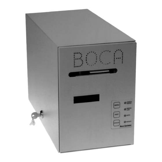
3.0 A Tour of Your Printer ticket output slot control panel Figure 2 - Micro Plus ticket printer Entrance Slot optical devices internal ticket compartment Figure 3 - Micro Plus side view... -
Page 10: Figure
(shown with cable) fuse holder (2amp slow blow) AC connector Figure 4 - Micro Plus rear view entrance slot main logic board hold down strap power supply logic board 110/220v Selector Board Figure 5 - Micro Plus side view with electronics exposed... -
Page 11: Installation
4.0 Installation The Micro Plus ticket printer is designed to be mounted on a desktop or on a shelf. The Micro Plus is available with an optional mounting plate for installation within a counter. However, prior to site preparation and installation, the printer should be powered up and run in the self test mode. -
Page 12: Configuration
5.0 Configuration The Micro Plus is factory configured for a variety of customer requirements. The print- er is available in a standard FGL20 electronics package or with an enhanced FGL40 package. Standard resolution is 200dpi and 300 dpi is available as an option. -
Page 13: Standard Interface Pinouts
6.0 Standard Interface Pinouts 6.1 Serial Pinouts RS232 (Standard) RS232 (PC type) Function Function Printer Transmit Printer Receive Printer Receive Printer Transmit Ground RTS (+5Vdc) 5,20 DTR (Printer Ready) DTR (Printer Ready) 4,22 RTS (+5Vdc) Ground CD (+5Vdc) 6.2 Typical RS232 Pin Connections (Standard) (Standard) (PC Type) -
Page 14: Thermal Paper - Theory And Specification
7.0 Thermal Paper - Theory & Specification The print head’s life expectancy is composed of both a mechanical and an electrical component. Both of these factors are strongly influenced by the quality of the thermal paper used. MECHANICAL The print head has a theoretical rating of 60 kilometers. This number is based upon the assumption that the head will be used with a good quality, top coated thermal paper. -
Page 15: Maintenance And Adjustments
8.0 Maintenance and Adjustments Your ticket printer is solidly constructed and has been designed for high volume use. It requires minimal care to provide maximum service. This section provides an overview of printer maintenance, including parts alignments, adjustment and replacement. For discussion purposes, the printer consists of two major modules or assemblies: •... -
Page 16: Optical Devices
The printer should advance the ticket just beyond the edge of the cabinet. The position of the tear can be controlled by changing the cut count setting in the OPERATOR MENU (see Appendix A). If you are not able get the desired tear position, then make sure your ticket stock was manufactured to proper specifications. -
Page 17: Thermal Print Head
8.1.6 THERMAL PRINT HEAD The print head should be cleaned periodically to prevent debris from building up on the print element. The required cleaning interval varies greatly depending on the quality of the ticket stock and the amount of dust entering the print area. Excessive dirt build up on the print head will result in reduced quality. -
Page 18: Print Head Removal
Figure 9a - Print Head removal Remove these two unmarked screws to replace print head. Figure 9b - Print Head removal Clean this surface. Figure 9c - Print Head removal... - Page 19 8.1.7 Rubber Drive Roller (Platen) The rubber drive roller should be cleaned once a year to prevent paper dust from building up on the roller. Clean drive roller with a paper towel and alcohol. 1. Unlock the thermal head and tilt back to gain access to platen. 2.
-
Page 20: General Cleaning
8.3a Power Supply Logic Board (Removal) 1. Gain access to the Logic Board Assembly by removing the sheet metal ticket tray. 2. Remove the Logic Board Assembly “hold down strap”. (see figure 5) 3. Unplug connectors going to the power supply logic board. 4. -
Page 21: Spare Parts List
9.0 Spare Parts List PART # DESCRIPTION P19-1000 AC CORD P31-1000 AC FILTER 492121 ANTI STATIC BRUSH (2” OR 3.25”) P45-1009 B EARING, EJECT BLOCK (LARGE) 04107GMN BEARING, EJECT MOTOR 422557-188 CABLE RIBBON, THERMAL HEAD (BS2008) 422557-18 CABLE RIBBON, THERMAL HEAD (3.25” & 4.0”) 18” 422557-16 CABLE RIBBON, THERMAL HEAD (3.25”... - Page 22 PART # DESCRIPTION P55-1002 LOCK, MINI PLUS (#305) 422270 LOGIC BOARD ASSY. (only) FGL 40 422188 LOGIC BOARD ASSY. (only) FGL 20 422189 LOGIC BOARD, POWER SUPPLY ( for FGL 40 & FGL 20 ) 430894 LOGIC BOARD, MTG. CLIPS 421428 OPTO MTG.
-
Page 23: Troubleshooting Guide
10.0 Troubleshooting Guide This is a simplified troubleshooting guide listing some of the typical problems. It is not intended to provide technical details or repair methods, but can serve as a guide to fault isolation in the If you need additional help, please contact BOCA at field. - Page 24 ERRACTIC PRINT POSITION a. See # 4 POOR PRINT OUT (light print out) a. Make sure the print head/cam lock assembly if fully locked in the closed position. b. Consult “Thermal Print Head” in Section 8.1.6. c. Clean print head. Consult “Thermal Print Head” in Section 8.1.6. d.
- Page 25 The FGL20 and FGL40 printers allow the user to adjust various printer options through the control panel. CHECK PAPER MENU Selects proper menu topic (baud rate, cut count, etc.) PAPER Enters new value / Also saves new values. TEST DATA Scrolls through choices in individual menu topics.
- Page 26 The chart below lists the present menu topics. These topics are subject to change. OPERATOR MENU! BAUD RATE? MINI/MICRO? PRINT SPEED? DIAGNOSTIC MODE? TICKET TYPE? STATUS ENABLED? TRANSPARENT MODE PAPER MODE? INC CUT1 COUNT? DEC CUT1 COUNT? INC CUT2 COUNT? DEC CUT2 COUNT? PRINT MODE? PRINT INTENSITY?
-
Page 27: Figure
Defines the type of printer. MINI Is for a printer with a Silent Cutter Assembly (SC2) ( Mini, Mini Plus, Mini MB, Dual Mini) MICRO Is for a printer without a SC2 (Micro, Micro Plus, Micro MB, Dual Micro) (factory default) PRINT SPEED? Controls the speed the ticket travels at. - Page 28 INC CUT2 COUNT? Same as INC CUT1 COUNT? but effects path #2 on a dual path printer. DEC CUT2 COUNT? Same as DEC CUT1 COUNT? but effects path #2 on a dual path printer. PRINT MODE? Defines the automatic ticket length calculation feature. THERMAL The printer will feed out and then retract a ticket during this measurement.
-
Page 29: Installation Instructions
INSTALLATION INSTRUCTIONS Vertical Micro Plus SITE PREPARATION Note: This Printer extends 17.0 inches below the top of the counter. TOP VIEW OF COUNTER Overhang of Top Plate Cut out this surface area 12.0 1.00 TOP PLATE INSTALLATION NOT TO SCALE... - Page 30 FGL PRINTER COMPARISON CHART FGL 20 FGL 40 Alphanumeric LCD Display Processing Speed (FGL II = 1) Customer Accessible Flash Memory 128 kbytes 128 kbytes Expansion Memory Option Maximum Print Speed 8 ips 10 ips Maximum Print Density 300 dpi 300 dpi Maximum Printable Area @ 200 dpi Maximum Printable Area @ 300 dpi...
Need help?
Do you have a question about the Micro Plus and is the answer not in the manual?
Questions and answers