Table of Contents
Advertisement
Quick Links
Advertisement
Table of Contents

Related Manuals for Boca Systems SUBATM


Summary of Contents for Boca Systems SUBATM
- Page 1 SUBATM MODEL TICKET PRINTER Operator’s Manual Rev B: 10/16/2002...
-
Page 2: Table Of Contents
Table of Contents Page FCC Notice & Warranty Information Introduction Unpacking the printer Important Safety Information Installation Configuration Standard Interface Pinouts Thermal Paper – Theory & Specifications Maintenance and Adjustments Paper Guide and Print Head Assembly 8.1.1 Load Switch and Cut Opto 8.1.2 Thermal Print Head 8.1.3... -
Page 3: Fcc Notice
FCC NOTICE NOTE: The equipment has been tested and found to comply with the limits for a class A digital device, pursuant to part 15 of the FCC rules. These limits are designed to provide reasonable protection against harmful interference when the equipment is operated in a commercial environment. -
Page 4: Introduction
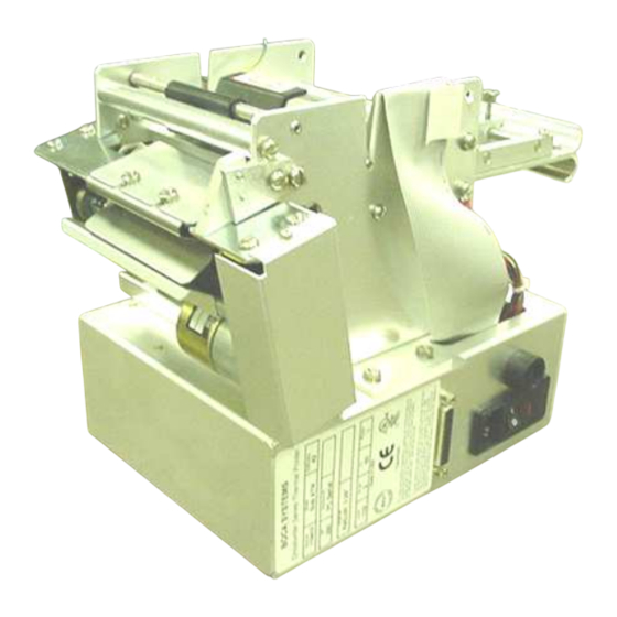
1.0 Introduction BOCA SubATM printer is a direct thermal ticket printer with an integrated cutting mechanism designed for self service (Kiosk) ticketing environments. This manual will provide the user with general information regarding printer set-up, configuration and troubleshooting. Please review the programming guide for additional details. -
Page 5: Important Safety Information
3.0 Important Safety Information WARNING: The appearance of this symbol indicates the proximity of an exposed high voltage area. Please follow all directions carefully for your personal safety. You must read the following safety information carefully before working on the printer. As a safety precaution, all service to the printer should be done by qualified persons with... -
Page 6: Installation
• Begin loading tickets through the entrance slot with a smooth motion until the printer automatically positions the ticket. NOTE: Tickets should be loaded with the black mark facing down. Refer to the BOCA systems website at www.bocasystems.com, THERMAL TICKETS... -
Page 7: Standard Interface Pinouts
6.0 Standard Interface Pinouts SERIAL PINOUTS RS232 (standard) RS232 (PC type) FUNCTION FUNCTION Printer Transmit Printer Receive Printer Receive Printer Transmit Ground RTS (+5V) 5,20 Printer Ready DTR (printer ready) 4,22 RTS (+5V) Ground CD (+5V) TYPICAL RS232 PIN CONNECTIONS (standard) (standard) (pc type) -
Page 8: Thermal Paper – Theory & Specifications
Thermal Paper - Theory & Specification Refer to the BOCA Systems website at www.bocasystems.com, THERMAL TICKETS section for the most current paper specifications. The print head’s life expectancy is composed of both a mechanical and an electrical component. Both of these factors are strongly influenced by the quality of the thermal paper used. -
Page 9: Maintenance And Adjustments
8.0 Maintenance and Adjustments Your ticket printer is solidly constructed and has been designed for high volume use. It requires minimal care to provide maximum service. WARNING: The appearance of this symbol indicates the proximity of an exposed high voltage area. Please follow all directions carefully for your personal safety. -
Page 10: Load Switch And Cut Opto
8.1.1 Load Switch and Cut Opto There is one micro switch located below the paper guide. This switch is used to sense the presence of ticket stock in the printer. The switch is factory set and adjustment should not be necessary. The load switch should be positioned such that the printer automatically activates the stepper motor at the proper time when tickets are loaded into the printer. - Page 11 There is one optical device mounted on an aluminum bracket. The opto controls the cut position. Removal or adjustment of the opto should be done without removing the bracket from the paper guide. The opto position is factory set and adjustment should not be necessary Note: Before making any opto adjustments make sure your ticket stock was manufactured to proper ticket specifications.
-
Page 12: Thermal Print Head
8.1.2 THERMAL PRINT HEAD The print head should be cleaned periodically to prevent debris from building up on the print element. The required cleaning interval varies greatly depending on the quality of the ticket stock and the amount of dust entering the print area. Excessive dirt build up on the print head will result in reduced quality. -
Page 13: Rubber Drive Roller
1. Make sure power is off and the AC cord is disconnected from the printer. 2. DO NOT UNPLUG CABLE FROM PRINT HEAD. 3. Open the red handled lever to remove pressure from the thermal head. 4. Disengage the screws that fasten the thermal print head to the mounting block. Allow the screws to remain in the mounting block. -
Page 14: Ticket Width Adjustment
8.1.4 Ticket Width Adjustment To adjust the paper path for use with a different ticket width, loosen the two thumbscrews located on the adjustable slide block. Slide the block to the fully open position. Insert your ticket stock into the paper guide. -
Page 15: Cutter Assembly
8.2 Cutter Assembly The silent cutter (SC2) system is a fully integrated rotary cutter mechanism powered by a DC motor. The SC2 requires no adjustments and is rated for approximately 750,000 cuts. Please be aware of the following: Wait five seconds before feeding ticket stock into the printer after power up. During this time the SC2 will rotate once. -
Page 16: Logic Board
8.3 Logic Board The printed circuit boards used in this product have been manufactured using surface mount technology. These printed circuit boards cannot be effectively repaired in the field and should be returned to the manufacturer if repair is required. Warning: ALL SERVICE SHOULD BE DONE WITH POWER OFF AND THE AC CORD UNPLUGGED FROM THE PRINTER. -
Page 17: Logic Board (Installation)
The interior of the printer should be cleaned whenever there is a visible accumulation of dust. Use a small vacuum for cleaning. Be careful not to jar any of the printer’s parts loose. Spare Parts List Refer to the BOCA Systems website at www.bocasystems.com, TECH SUPPORT section for the most current Spare Parts List. - Page 18 P50-1002 DRIVE BELT, 89T P51-1007 DRIVE PULLEY, 20T (Large ID .25”) P51-1014 DRIVE PULLEY, 20T (small ID 5mm) Used on printers with LCD displays P51-1010 DRIVE PULLEY, 22T (Large ID ) P51-1015 DRIVE PULLEY, 22T (small ID 5mm) Used on printers with LCD displays P51-1011 DRIVE PULLEY, 30T P51-1002...
- Page 19 421385-5M3 PLATEN 3.25” 200 OR 300 DPI (Ghost, Mini, Vmini, MiniMB & Mini Plus) 421508W-2 PLATEN 3.25” 200 OR 300 DPI (Micro, Micro Plus, VM, Dual & Mini Plus SM) 421385W-NMIC PLATEN 3.25” 200 OR 300 DPI (Micro MB) 421508VAR-MPL PLATEN 4.00”...
-
Page 20: Troubleshooting Guide
10.0 Troubleshooting Guide This is a simplified troubleshooting guide listing some of the typical problems. It is not intended to provide As a safety technical details or repair methods, but can serve as a guide to fault isolation in the field. precaution, all service to the printer should be done by qualified persons with power off and... - Page 21 POOR PRINT OUT (light print out) a. Make sure the print head/cam lock assembly if fully locked in the closed position. b. Consult “Thermal Print Head” section. c. Clean print head. Consult “Thermal Print Head” section. d. Adjust print intensity setting via the control panel. (see Appendix A) e.
-
Page 22: Appendix A
APPENDIX A - CONTROL PANEL The FGL44 printers allow the user to adjust various printer options through the control panel. To access the control panel menu, press both MENU and TEST switches simultaneously for about 3 seconds. The LCD will display the “OPERATOR MENU!”... - Page 23 The following is a brief overview of some representative Menu options: BAUD RATE? Controls the serial interface baud rate, parity bit, data bits and stop bits. Here are the following choices: 1200,N,8,1 4800,N,8,1 19200,N,8,1 38400,E,7,1 1200,E,7,1 4800,E,7,1 19200,E,7,1 57600,N,8,1 1200,O,7,1 4800,O,7,1 19200,0,7,1 57600,E,7,1...
Need help?
Do you have a question about the SUBATM and is the answer not in the manual?
Questions and answers