
Related Manuals for Boca Systems Dual Micro


Summary of Contents for Boca Systems Dual Micro
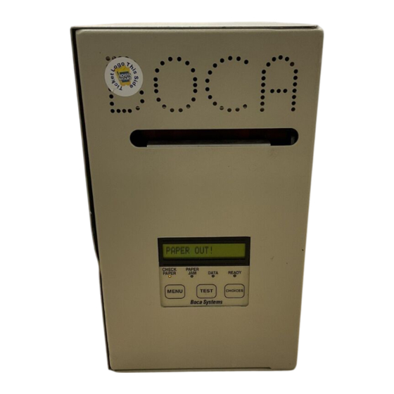
- Page 1 MICRO MODEL TICKET PRINTERS Operator’s Manual Rev A: 10/16/2002 MICRO MICRO PLUS SubMICRO DUAL MICRO...
-
Page 2: Table Of Contents
Table of Contents Page FCC Notice & Warranty Information Introduction Unpacking the printer Important Safety Information Installation Configuration Standard Interface Pinouts Thermal Paper – Theory & Specifications Maintenance and Adjustments Paper Guide and Print Head Assembly 8.1.1 Load Switch and Tear Opto 8.1.2 Thermal Print Head 8.1.3... -
Page 3: Fcc Notice
FCC NOTICE NOTE: The equipment has been tested and found to comply with the limits for a class A digital device, pursuant to part 15 of the FCC rules. These limits are designed to provide reasonable protection against harmful interference when the equipment is operated in a commercial environment. -
Page 4: Introduction
1.0 Introduction BOCA MICRO series printers are direct thermal ticket printers designed for point of sale ticketing environments. This manual will provide the user with general information regarding printer set-up, configuration and troubleshooting. Please review the programming guide for additional details. -
Page 5: Important Safety Information
3.0 Important Safety Information WARNING: The appearance of this symbol indicates the proximity of an exposed high voltage area. Please follow all directions carefully for your personal safety. You must read the following safety information carefully before working on the printer. As a safety precaution, all service to the printer should be done by qualified persons with... -
Page 6: Installation
• Begin loading tickets through the entrance slot with a smooth motion until the printer automatically positions the ticket. NOTE: Tickets should be loaded with the black mark facing down. Refer to the BOCA systems website at www.bocasystems.com, THERMAL TICKETS... -
Page 7: Standard Interface Pinouts
6.0 Standard Interface Pinouts SERIAL PINOUTS RS232 (standard) RS232 (PC type) FUNCTION FUNCTION Printer Transmit Printer Receive Printer Receive Printer Transmit Ground RTS (+5V) 5,20 Printer Ready DTR (printer ready) 4,22 RTS (+5V) Ground CD (+5V) TYPICAL RS232 PIN CONNECTIONS (standard) (standard) (pc type) -
Page 8: Thermal Paper – Theory & Specifications
Thermal Paper - Theory & Specification The print head’s life expectancy is composed of both a mechanical and an electrical component. Both of these factors are strongly influenced by the quality of the thermal paper used. MECHANICAL The print head has a theoretical rating of 60 kilometers. This number is based upon the assumption that the head will be used with a good quality, top coated thermal paper. -
Page 9: Maintenance And Adjustments
8.0 Maintenance and Adjustments Your ticket printer is solidly constructed and has been designed for high volume use. It requires minimal care to provide maximum service. WARNING: The appearance of this symbol indicates the proximity of an exposed high voltage area. Please follow all directions carefully for your personal safety. -
Page 10: Load Switch And Tear Opto
8.1.1 Load Switch and Tear Opto There is one micro switch located below the paper guide. This switch is used to sense the presence of ticket stock in the printer. The switch is factory set and adjustment should not be necessary. - Page 11 There is one optical device mounted on an aluminum bracket. The opto controls the tear position. Removal or adjustment of the opto should be done without removing the bracket from the paper guide. The opto position is factory set and adjustment should not be necessary To adjust the tear position, use the INC/DEC CUT1/2 settings on the control panel.
-
Page 12: Thermal Print Head
8.1.2 THERMAL PRINT HEAD The print head should be cleaned periodically to prevent debris from building up on the print element. The required cleaning interval varies greatly depending on the quality of the ticket stock and the amount of dust entering the print area. Excessive dirt build up on the print head will result in reduced quality. -
Page 13: Rubber Drive Roller
FOR PRINTERS WITH RED HANDLED LEVER 1. Make sure power is off and the AC cord is disconnected from the printer. 2. DO NOT UNPLUG CABLE FROM PRINT HEAD. 3. Open the red handled lever to remove pressure from the thermal head. 4. -
Page 14: Ticket Width Adjustment
8.1.4 Ticket Width Adjustment To adjust the paper path for use with a different ticket width, loosen the two thumbscrews located on the adjustable slide block. Slide the block to the fully open position. Insert your ticket stock into the paper guide. -
Page 15: Logic Board (Removal)
Warning: ALL SERVICE SHOULD BE DONE WITH POWER OFF AND THE AC CORD UNPLUGGED FROM THE PRINTER. See below pictures for main logic board access: MICRO MICRO PLUS (Remove ticket locator) SubMICRO DUAL MICRO (Access rear panel) (Access bottom of cabinet) 8.2.1 Logic Board (Removal) -
Page 16: Logic Board (Installation)
The interior of the printer should be cleaned whenever there is a visible accumulation of dust. Use a small vacuum for cleaning. Be careful not to jar any of the printer’s parts loose. Spare Parts List Refer to the BOCA Systems website at www.bocasystems.com, TECH SUPPORT section for the most current Spare Parts List. - Page 17 PAPER GUIDE TOP PLATE, Adjustable 4” with top mounting optos 422234 PLATEN 1.328” SPECIAL 421508N-2 PLATEN 2.00” 200 OR 300 DPI (Micro, Micro Plus, VM, Dual & Mini Plus SM) 421385N-MIC PLATEN 2.00” 200 OR 300 DPI (Micro MB) 421508W-2 PLATEN 3.25”...
- Page 18 TICKET CATCHER, (SET) (Vertical Ghostwriter) 421421-MIC5M TOP PLATE (MICRO 2.00” & 3.25”) 421421-MIC5M4 TOP PLATE (MICRO 4.00”) 421421-MICP5 TOP PLATE (MICRO PLUS 2.00” & 3.25”) 421421-ZZ TOP PLATE (MICRO PLUS 4.00”) 422808-230 TRANSFORMER, 220VAC (FGL41, 21,22 & 42) 422808-115 TRANSFORMER, 110VAC (FGL41, 21, 22 & 42)
-
Page 19: Troubleshooting Guide
10.0 Troubleshooting Guide This is a simplified troubleshooting guide listing some of the typical problems. It is not intended to provide As a safety technical details or repair methods, but can serve as a guide to fault isolation in the field. precaution, all service to the printer should be done by qualified persons with power off and... - Page 20 a. Clean print head. Consult “Thermal Print Head” section. b. Replace thermal head. NO PRINT OUT a. Check head cable for electrical connection at both ends b. Check to make sure head cable is plugged in properly into the thermal head. c.
-
Page 21: Appendix A
The chart below lists the present menu topics. These topics are subject to change. OPERATOR MENU FACTORY MENU FACTORY MENU (Continued) BAUD RATE? BAUD RATE? DEC CUT2 COUNT? MINI/MICRO? MINI/MICRO? PRINT MODE? PRINT SPEED? PRINT SPEED? 2-SIDED PRINTER? DIAGNOSTIC MODE? - Page 22 Is for a printer with a Silent Cutter Assembly (SC2) (Mini, Mini Plus, Mini MB, Dual Mini) MICRO Is for a printer without a SC2 (Micro, Micro Plus, Micro MB, Dual Micro) PRINT SPEED? Controls the speed the ticket travels at. Also effects the print quality.
Need help?
Do you have a question about the Dual Micro and is the answer not in the manual?
Questions and answers