
Related Manuals for Boca Systems Mini MB


Summary of Contents for Boca Systems Mini MB
- Page 1 MINI MODEL TICKET PRINTERS Operator’s Manual MINI MB MINI PLUS SUBMINI XMINI DUAL MINI Rev E: 04/16/2006...
-
Page 2: Table Of Contents
Table of Contents Page FCC Notice & Warranty Information Introduction Unpacking the printer Important Safety Information Installation Configuration Standard Interface Pinouts Thermal Paper – Theory & Specifications Maintenance and Adjustments Paper Guide and Print Head Assembly 8.1.1 Load Switch and Cut Opto 8.1.2 Thermal Print Head 8.1.3... -
Page 3: Fcc Notice
FCC NOTICE NOTE: The equipment has been tested and found to comply with the limits for a class A digital device, pursuant to part 15 of the FCC rules. These limits are designed to provide reasonable protection against harmful interference when the equipment is operated in a commercial environment. -
Page 5: Introduction
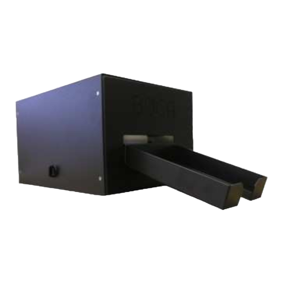
1.0 Introduction BOCA MINI series printers are direct thermal ticket printers with an integrated cutting mechanism. This manual will provide the user with general information regarding printer set-up, configuration and troubleshooting. Please read the important safety information section before installation is conducted. Review the programming guide for additional details. -
Page 6: Important Safety Information
3.0 Important Safety Information WARNING: The appearance of this symbol indicates the proximity of an exposed high voltage area. Please follow all directions carefully for your personal safety. You must read the following safety information carefully before working on the printer. As a safety precaution, all service to the printer should be done by qualified persons with... -
Page 7: Installation
• Begin loading tickets through the entrance slot with a smooth motion until the printer automatically positions the ticket. NOTE: Tickets should be loaded with the black mark facing down. Refer to the BOCA systems website at www.bocasystems.com, THERMAL TICKETS... -
Page 8: Standard Interface Pinouts
6.0 Standard Interface Pinouts SERIAL PINOUTS RS232 (standard) RS232 (PC type) FUNCTION FUNCTION Printer Transmit Printer Receive Printer Receive Printer Transmit Ground RTS (+5V) 5,20 Printer Ready DTR (printer ready) 4,22 RTS (+5V) Ground CD (+5V) TYPICAL RS232 PIN CONNECTIONS (standard) (standard) (pc type) -
Page 9: Thermal Paper – Theory & Specifications
Thermal Paper - Theory & Specification Refer to the BOCA Systems website at www.bocasystems.com, THERMAL TICKETS section for the most current paper specifications. The print head’s life expectancy is composed of both a mechanical and an electrical component. Both of these factors are strongly influenced by the quality of the thermal paper used. -
Page 10: Maintenance And Adjustments
8.0 Maintenance and Adjustments Your ticket printer is solidly constructed and has been designed for high volume use. It requires minimal care to provide maximum service. WARNING: The appearance of this symbol indicates the proximity of an exposed high voltage area. Please follow all directions carefully for your personal safety. -
Page 11: Load Switch And Cut Opto
8.1.1 Load Switch and Cut Opto There is one micro switch located below the paper guide. This switch is used to sense the presence of ticket stock in the printer. The switch is factory set and adjustment should not be necessary. The load switch should be positioned such that the printer automatically activates the stepper motor at the proper time when tickets are loaded into the printer. - Page 12 There is one optical device mounted on an aluminum bracket. The opto controls the cut position. Removal or adjustment of the opto should be done without removing the bracket from the paper guide. The opto position is factory set and adjustment should not be necessary Note: Before making any opto adjustments make sure your ticket stock was manufactured to proper ticket specifications.
-
Page 13: Thermal Print Head
8.1.2 THERMAL PRINT HEAD The print head should be cleaned periodically to prevent debris from building up on the print element. The required cleaning interval varies greatly depending on the quality of the ticket stock and the amount of dust entering the print area. -
Page 14: Rubber Drive Roller
Head is installed wrong. Should not Photo D be sitting on top of the cutter. Click here to return to > Table of Contents 8.1.3 Rubber Drive Roller (Platen) The rubber drive roller should be cleaned once a year to prevent paper dust from building up on the roller. -
Page 15: Ticket Width Adjustment
8.1.4 Ticket Width Adjustment To adjust the paper path for use with a different ticket width, loosen the two thumbscrews located on the adjustable slide block. Slide the block to the fully open position. Insert your ticket stock into the paper guide. -
Page 16: Cutter Assembly
8.2 Cutter Assembly The BOCA cutter (BC2) system is a fully integrated cutter knife mechanism powered by a stepper motor. The BC2 requires no adjustments and is rated for approximately 750,000 cuts. Please be aware of the following: Wait five seconds before feeding ticket stock into the printer after power up. During this time the BC2 cutter knife will move up and down. -
Page 17: Logic Board
Warning: ALL SERVICE SHOULD BE DONE WITH POWER OFF AND THE AC CORD UNPLUGGED FROM THE PRINTER. See below pictures for main logic board access: MINI MB, SUBMINI, XMINI MINI PLUS (Access bottom panel) (Access rear panel) -
Page 18: Logic Board (Installation)
CONTROL PANEL, MTG PLATE for FGL 22-44 (MiniMB, Mini+, Micro+ & Mag)w/ decal 421701-2MBMINI COVER, MINI MB model printer for paper guide side 421701-1MBMINI COVER, MINI MB model printer for door side including mtg. hardware 420881submini-2 COVER, MINI MB (new model) side with the plastic latch 420881XMBMINI... - Page 19 GROUND STRAP FOR THERMAL HEAD MTG. BLOCK (TOH) 422891 HARNESS, DC FOR MINIMB 422892 HARNESS, AC FOR MINI MB 422637-TA HEAD MTG. BLOCK TAKE OUT HEAD ASSY for an ADJW (complete) 421359-5MMB HEAD MTG. BLOCK TAKE OUT HEAD ASSY for an RADJW (complete) 423496 HEAD MTG.
-
Page 20: Troubleshooting Guide
421421-M41P TOP PLATE, VM SPECIAL for 2" & 3.25" fixed VM model printer (10.25" x 10.25") 421988-2 TOP PLATE, Dual Mini (3.25" x 3.25" paper paths 422888-230* TRANSFORMER, 220VAC for FGL24 and FGL44 model printer 422888-115* TRANSFORMER, 110VAC for FGL24 and FGL44 model printer Click here to return to >... - Page 21 a. Check for blockage in the cutter area. c. Default printer settings. With the printer powered off hold down the TEST button and then power up the printer. Keep the TEST button held down for ten seconds and release. c. Replace the cutter motor d.
-
Page 22: Appendix A - Control Panel
APPENDIX A - CONTROL PANEL The FGL44 printers allow the user to adjust various printer options through the control panel. To access the control panel menu, press both MENU and TEST switches simultaneously for about 3 seconds. The LCD will display the “OPERATOR MENU!”... - Page 23 MINI/MICRO? Defines the type of printer. MINI Is for a printer with a Silent Cutter Assembly (SC2) (Mini, Mini Plus, Mini MB, Dual Mini) MICRO Is for a printer without a SC2 (Micro, Micro Plus, Micro MB, Dual Micro) PRINT SPEED? Controls the speed the ticket travels at. Also effects the print quality.
-
Page 24: Appendix B - Vertical Printer Installation
APPENDIX B - VERTICAL PRINTER INSTALLATION Prepare the counter top by cutting a rectangular hole in accordance with the dimensions specified for your printer model. NOTE: The table or counter top must be able to support at least four times the weight of the printer. - Page 25 APPENDIX C - DUAL MINI PATH 2 PATH 1 Silent Cutter (SC2) This section will go over some of the unique features of the Dual Mini model printer. • The Dual Mini has a load opto configuration. The opto closer to where you load the stock is the ticket load opto.
Need help?
Do you have a question about the Mini MB and is the answer not in the manual?
Questions and answers