Table of Contents
Advertisement
Advertisement
Table of Contents

Related Manuals for Boca Systems FSP 42


Summary of Contents for Boca Systems FSP 42
- Page 1 FSP 42/44/46 Flight Strip Printer Technical Manual Revision D: 04.18.08...
- Page 2 BOCA SYSTEMS, INC. © 2008 Boca Systems, Inc. All rights reserved. Under the copyright laws, this manual may not be copied, in whole or in part, without the written consent of BOCA. Every effort has been made to ensure that the information in this manual is accurate.
-
Page 3: Table Of Contents
Table of Contents Page Introduction Unpacking the Printer A tour of your printer Installation Loading Flight Strips Standard Configuration This Section has been removed Control Panel Indicators 6.0. Interface Pinouts Thermal Paper - Theory and Specification Maintenance and Adjustments Paper Guide and Print Head assembly 8.1.5 Optical Devices 8.1.5.5 Ticket Load Switch 8.1.6 Thermal Print Head... - Page 4 Table of Figures and Appendices Page Figure 1 Packaging Figure 2a Control Panel and LCD Figure 2b Flight Strip Printer(FSP) Figure 2c Cabinet Lock Mechanism Figure 3a FSP side view Figure 3b FSP , cover open Figure 4 FSP, rear view Figure 5 Adjustable paper path Figure 6...
-
Page 5: Fcc Notice
FCC NOTICE NOTE: The equipment has been tested and found to comply with the limits for a class A digital device, pursuant to part 15 of the FCC rules. These limits are designed to provide reasonable protection against harmful interference when the equipment is operated in a commercial environment. -
Page 6: Warranty Information
WARRANTY INFORMATION PRINTERS - BOCA warrants each printer to be free of defects for a period of one year from the date of shipment when subject to normal use and service. This warranty cov- ers all parts and labor except for the print head which is warranted for 90 days. All warranty labor is to be performed at the BOCA facility. -
Page 7: Introduction
1.0 Introduction The BOCA Flight Strip Printer, (FSP) is a direct thermal ticket printer with an integrated cutting mechanism designed for air traffic control environments. This manual will provide the user with general information regarding printer set-up, configuration and troubleshooting. Please review your programming guide for additional details. -
Page 8: Unpacking The Printer
2.0 Unpacking the Printer The printer is shipped in a ruggedized container. Please save packing material for future use. Remove the printer (see figure 1) and accessories from the box and inspect for obvious damage. If damage is noticed, please report it immediately to BOCA. -
Page 9: A Tour Of Your Printer
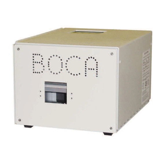
3.0 A Tour of Your Printer Figure 2a - Control Panel and LCD Output Slot (Hopper Mounting Holes) Figure 2b - Flight Strip Printer (FSP) Figure 2c - Cabinet Lock Mechanism... -
Page 10: Figure
Figure 3a - FSP , Side View A. Cutter Assembly B. Optical Detector NOTE: C. Timing Belt THE CUTTER ASSEMBLY MAY VARY D. Drive Pulley (2) DEPENDING ON THE DATE OF E. Transformer MANUFACTURE OF THE PRINTER. THE SC2 CUTTER IS SHOWN. F. -
Page 11: Fsp , Cover Open
Figure 3b - FSP , Cover Open A. Print Head Release Lever B. Logic Board NOTE: C. LCD Control Board LOGIC BOARD CONFIGURATIONS MAY VARY DEPENDING ON THE DATE OF MANUFACTURE OF THE PRINTER. THE FGL42 LOGIC BOARD IS SHOWN. -
Page 12: Fsp, Rear View
Figure 4 - FSP , Rear View A. AC Power Connector NOTE: B. Fuse Holder (2amp,SB) CONFIGURATION MAY VARY C. Input Slot DEPENDING ON THE DATE OF D. Interface Connector (Serial) MANUFACTURE OF THE E. Locking Mechanism PRINTER FGL42 LOGIC BOARD CONFIGURATION SHOWN. -
Page 13: Installation
4.0 Installation The FSP is designed to be mounted on a counter top or shelf. However, prior to site and installation, the printer should be powered up and run in the self test preparation mode. L ay the printer flat on a counter. Please confirm that the line voltage agrees with the voltage listed on the label affixed to the side of the unit (see figure 4). -
Page 14: Flight Strip Loading
You may now install the printer in its permanent location. Adequate room should be provided behind the printer for the smooth feeding of stock. Begin loading flight strips through the entrance slot (figure 7) with a smooth motion until the printer automatically positions the flight strip. NOTE: Flight Strips should be loaded with the black mark facing down in the feed direction shown below (figure 7). -
Page 15: Standard Configuration
5.0 Standard Configuration The FSP is factory configured for specific customer requirements using an enhanced FGL package. Printing resolution is 300 dots per inch. For complete informa tion the FGL Programming Language, please see the programming guide. FGL printers allow the user to adjust various printer options through the control panel. CHECK PAPER PAPER... -
Page 16: Baud Rate
The chart below lists the present menu topics. These topics are subject to change. The following is an overview of what each Menu option does: TEST TICKET TYPE? The FSP allows one of four different test tickets to be printed when the printer’s test button is pressed. -
Page 17: Ticket Load Switch
MINI/MICRO? Defines the type of printer. MINI Is for a printer with a Cutter Assembly (factory default) MICRO Is for a printer without a Cutter Assembly PRINT SPEED? Controls the speed the ticket travels at. Also effects the print quality. The numbers range from 0 - FASTEST to 7 - SLOWEST. -
Page 18: Default Setting
SPECIAL HEAD? Is used when a special paper path size is installed (2.125”, 2.5”, 2.7”...) Here are the following choices: NO special head (factory default) ON P1 SINGLE PATH PRINTER ONLY. DUAL PATH PRINTER PATH #1 ON P2 DUAL PATH PRINTER PATH #2 ON BOTH DUAL PATH PRINTER BOTH PATHS REV ADJ2 P1... -
Page 19: Print Mode
INC CUT2 COUNT? Same as INC CUT1 COUNT? but effects path #2 on a dual path printer. (Does not apply) DEC CUT2 COUNT? Same as DEC CUT1 COUNT? but effects path #2 on a dual path printer. (Does not apply) 2-SIDED PRINTER? Only used with 2S ticket printers. - Page 20 FLASH ACK MODE? Enables or disables an ACK being sent back to the host after a flash operation. Your choices are YES (Enabled) or NO (Disabled). NO is factory default. SOFTWARE BUSY? Defines if the printer will go busy after each byte is received. Your choices are YES (Enabled) or NO (Disabled).
-
Page 21: This Section Has Been Removed
5.1 THIS SECTION HAS BEEN REMOVED This page has been left blank intentionally... -
Page 22: Control Panel Indicators
5.2 Control Panel Indicator Status Patterns (Flashing). Flashing errors have equal on and off time. Paper Out of Error No. Description Ready Data paper Flash erase operation incomplete Flash Vpp problem Flash byte erase error Flash Sequence error Flash block erase error Bad flash Flash program operation incomplete Flash byte program error... -
Page 23: Interface Pinouts
6.0 Interface Pinouts Serial Pinouts RS232 (Standard) Function Printer Transmit Printer Receive Ground 5,20 DTR (Printer Ready) 4,22 RTS (+5Vdc) Typical RS232 Pin Connections (Standard) (Standard) 25 PIN PC 9 PIN PC BOCA BOCA 3 RXD 2 RXD 2 TXD 3 TXD 7 GND 5 GND... -
Page 24: Thermal Paper - Theory And Specification
7.0 Thermal Paper - Theory & Specification The print head’s life expectancy is composed of both a mechanical and an electrical component. Both of these factors are strongly influenced by the quality of the thermal paper used. MECHANICAL The print head has a theoretical rating of 60 kilometers. This number is based upon the assumption that the head will be used with a good quality, top coated thermal paper. -
Page 25: Maintenance And Adjustments
8.0 Maintenance and Adjustments Your ticket printer is solidly constructed and has been designed for high volume use. It requires minimal care to provide maximum service. This section provides an overview of printer maintenance, including part alignments, adjustment and replacement. For discussion purposes, the printer consists of three major modules or assemblies: •... -
Page 26: Ticket Load Switch
FEED DIRECTION Optical Device, Ticket Cut Paper Guide ” Allen Head Screws On some models these connectors plug into the back of the circuit board Grn/Red/Blk Wires Figure 8 - Optical Device TO LOGIC BOARD 8.1.5.5 Ticket Load Switch The ticket load switch should be positioned such that the printer automatically activates the stepper motor at the proper time when tickets are loaded into the printer. -
Page 27: Thermal Print Head
8.1.6 THERMAL PRINT HEAD The print head should be cleaned periodically to prevent debris from building up on the print element. The required cleaning interval varies greatly depending on the quality of the ticket stock and the amount of dust entering the print area. Excessive dirt build up on the print head will result in reduced quality. - Page 28 Print Head release lever. Remove these two unmarked screws to replace print head. Adjustment set screws Figure 9a - Print Head removal Figure 9b - Print Head removal Figure Figure - Print Head removal Clean this surface Head is installed wrong. Should no be sitting on top of the cutter.
-
Page 29: Cutter Assembly
8.2 Cutter Assembly NOTE: THE CUTTER ASSEMBLY MAY VARY DEPENDING ON THE DATE OF MANUFACTURE OF THE PRINTER 8.2a SC Cutter Assembly (SC2) The SC cutter (SC2) system is a fully integrated rotary cutter mechanism powered by a DC motor. The SC2 requires no adjustments and is rated for approximately 750,000 cuts. -
Page 30: Parts List
9.0 PARTS LIST ITEM Part Numbers Description 423182 CABINET, FSP 423182CV COVER, FSP 423111FSP PRINT CAGE, FSP 421366FSP PAPER GUIDE, FSP (LOWER) 421367FSP PAPER GUIDE, UPPER 422468FSP BEZEL 423182-1 FRONT PLATE, FSP 420947FSP CONNECTOR PLATE 423170FSP SWITCH XFER PLATE 421428FSP BKT, OPTO MNTG 426816VMINISC2 CUTTER MNTG PLATE (SC2 ONLY) -
Page 31: Troubleshooting Guide
10.0 Troubleshooting Guide This is a simplified troubleshooting guide listing some of the typical problems. It is not intended to provide technical details or repair methods, but can serve as a guide for fault isolation in the If you need additional help, please contact BOCA at field. - Page 32 POOR PRINT OUT (light print out) a. Make sure the print head/cam lock assembly if fully locked in the closed position. b. Consult “Thermal Print Head” in Section 8.1.6. c. Adjust print intensity setting via the control panel. Consult Section 5.0 d.
Need help?
Do you have a question about the FSP 42 and is the answer not in the manual?
Questions and answers