Table of Contents
Advertisement
Advertisement
Table of Contents

Subscribe to Our Youtube Channel
Related Manuals for Boca Systems LEMUR-ERAM


Summary of Contents for Boca Systems LEMUR-ERAM
- Page 1 LEMUR-ERAM FLIGHT STRIP PRINTER User Manual RevA: 10.04.19...
-
Page 2: Table Of Contents
Table of Contents Page FCC Notice & Warranty Information Introduction Unpacking the printer Important Safety Information Printer Tour Installation and Flight Strip Loading Control Panel Options Maintenance and Adjustments Paper Guide and Print Head Assembly 7.1.1 Cut Opto Assembly 7.1.2 Thermal Print Head 7.1.3 Thermal Print Head Replacement... -
Page 3: Fcc Notice & Warranty Information
FCC NOTICE NOTE: The equipment has been tested and found to comply with the limits for a class B digital device, pursuant to part 15 of the FCC rules. These limits are designed to provide reasonable protection against harmful interference when the equipment is operated in a commercial environment. This equipment generates, uses, and can radiate radio frequency energy and, if not installed and used in accordance with the instruction manual, may cause harmful interference to radio communications. -
Page 4: Introduction
1.0 Introduction The BOCA Lemur-ERAM is a direct thermal flight strip printer. This manual will provide the user with general information regarding printer set-up, operational instructions and detailed technical information. 2.0 Unpacking the Printer The printer is shipped in a ruggedized container. Please save packing material for future use. Remove the printer and accessories from the box and inspect for obvious damage. -
Page 5: Important Safety Information
3.0 Important Safety Information WARNING: The appearance of this symbol indicates the proximity of an exposed high voltage area. Please follow all directions carefully for your personal safety. You must read the following safety information carefully before working on the printer. As a safety precaution, all service to the printer should be done by qualified persons with power off... -
Page 6: Printer Tour
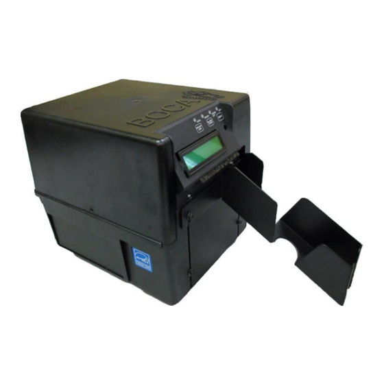
4.0 Printer Tour The following photos are presented for the purpose of familiarizing the user with the Lemur-ERAM Flight Strip Printer. Lemur-ERAM Flight Strip Printer Hopper Control Panel & LCD Display Flight Strip Feed Slot Hopper mounting screws AC Power... - Page 7 ON/OFF Switch Cam Lock Lever Cover Velcro attachment strips Print Head Mounting Plate Above shows printer with cover removed...
-
Page 8: Installation And Flight Strip Loading
5.0 Installation and Flight Strip Loading The Lemur-ERAM flight strip printer is designed to be mounted either on a desktop or shelf. Prior to site preparation, installation and loading of flight strips, the printer should be powered up and run in the self-test mode. -
Page 9: Control Panel Options
6.0 Control Panel Options The FAA-ERAM printer allows the user to adjust various printer options through the front control panel. MENU: Selects proper ON/OFF LINE: Scrolls menu topic (baud rate, cut through choices in count, etc.) individual menu topics LCD Dimmer BLANK STRIP: Enters and saves new values. - Page 10 To access and use the FACTORY MENU, follow these steps: 1. Ticket stock should be loaded into the printer and the printer powered on. 2. Press and hold the MENU button first, while continuing to keep the MENU button depressed press and hold the ON/OFF LINE button for approximately two seconds.
- Page 11 TICKET TYPE? Defines how the optos are configured on the paper guide assembly. Here are the following choices: NORMAL Both optos are inline with each other (usually mounted on a black bracket) A gap opto is installed on the cutter to detect gap in ticket stock. LABEL Same as GAP but the cut opto is to detect black mark on stock.
- Page 12 PATH TYPE? Defines the number of paper paths used. Here are the following choices: PATH1 Locks a Dual path printer onto path #1 (DEFAULT) PATH2 Locks a Dual path printer onto path #2 DUAL Is used for Dual path printer DUAL SUPPLY Please consult your Programming Guide (Dual Printer Supplement) VENTEK DUAL...
- Page 13 SKI MODE? Enables the operator to set an unprintable area on the first .50” of a ticket. This is ideally used for label stock. Your choices are YES (Enabled) or NO (Disabled). NO is default FLASH ACK MODE? Enables or disables an ACK being sent back to the host after a flash operation. Your choices are YES (Enabled) or NO (Disabled).
-
Page 14: Maintenance And Adjustments
7.0 Maintenance and Adjustments Your Lemur-ERAM flight strip printer is solidly constructed and has been designed for high volume use. It requires minimal care to provide maximum service. WARNING: The appearance of this symbol indicates the proximity of an exposed high voltage area. Please follow all directions carefully for your personal safety. -
Page 15: Cut Opto Assembly
7.1.1 Cut Opto Assembly There is one optical sensor (opto) mounted on an adjustable aluminum bracket. The opto controls the cut or tear position. Removal or adjustment of the opto should be done without removing the bracket from the paper guide. -
Page 16: Thermal Print Head
7.1.2 THERMAL PRINT HEAD The print head should be cleaned periodically to prevent debris from building up on the print element. The required cleaning interval varies greatly depending on the quality of the ticket stock and the amount of dust entering the print area. Excessive dirt build up on the print head will result in reduced quality. - Page 17 6. Lift the print head mounting plate straight out. 7. Clean the thermal print head surface (the side that makes contact with the paper) with isopropyl alcohol & paper towel. Mounting Plate Tab Mounting Plate Tab Clean This Surface 8. Install the head mounting plate by reversing the above procedures. Make sure the print head mounting plate tabs are in the back slot of the print cage slots.
-
Page 18: Thermal Print Head Replacement
7.1.3 THERMAL PRINT HEAD REPLACEMENT The following is done with the printer powered off and unplugged from the AC source. 1. Remove the print head mounting plate from the printer (Refer to section 7.1.2 THERMAL PRINT HEAD). 2. Once the head plate has been removed; loosen the two Philip head screws until the thermal print head disengages from the head plate. -
Page 19: Load Opto
7.1.4 Load Opto The Load SQ Opto is located on the paper guide assembly. The purpose of this optical sensor is to sense the presence of flight strips. No adjustment is required. You may gain access to this sensor by removing the print head assembly (Refer to section 7.1.2 Thermal Print Head). -
Page 20: Platen
7.1.5 Platen The Platen (rubber drive roller) should be cleaned once a year to prevent paper dust from building up on the roller. (NOTE: The platen may require more frequent cleaning in dusty environments or when using inferior ticket stock.) The following needs to be done with the printer powered off and unplugged from the AC source. -
Page 21: Cutter Assembly
7.2 Cutter Assembly The cutter system is a fully integrated cutter knife mechanism powered by a stepper motor. The cutter requires no adjustments and is rated for approximately 1,000,000 cuts. Please be aware of the following: The cutter area where the flight strips exit the printer should be blown out with air periodically to prevent debris from building up inside the cutter area. -
Page 22: Removal And Replacement Of Major Assemblies
8.0 Removal and Replacement of Major Assemblies WARNING: All Service must be done with the printer off and the AC cord unplugged from the printer. 8.1 Logic Board Removal/Replacement The printed circuit boards used in this product have been manufactured using surface mount technology. These printed circuit boards cannot be effectively repaired in the field. -
Page 23: Cut Opto Removal/ Replacement
8.2 Cut Opto Removal/Replacement Make sure power is off and the AC cord is disconnected from the printer. 2. Remove head mounting plate. (Refer to section 7.1.2 Thermal Print Head). 3. Remove the four 3/16” hex head screws that hold the upper paper guide in place. 4. -
Page 24: Load Opto Removal/ Replacement
8.3 Load Opto Removal/Replacement Make sure power is off and the AC cord is disconnected from the printer. 2. Remove the electrical cover from the printer (Refer to section 8.1 Logic Board Removal). 3. Remove the four Philip head screws that hold the print cage onto the electrical cover. 4. - Page 25 7. There is a washer just under the black SQ load opto mounting bracket that must not be removed. When installing the opto back in place make sure the tab on the black opto mounting bracket lines up with the slot in the paper guide. Installed the flat washer and ¼” nut back in place then tighten. SLOT 8.
-
Page 26: Control Panel Removal/ Replacement
8.4 Control Panel Removal/Replacement Make sure power is off and the AC cord is disconnected from the printer. 2. Remove the three 3/16” hex head screws that hold the control panel in place. 3. Remove the Philip head screw that secures the ground wires to the cutter assembly. 4. -
Page 27: Power Switch Removal/ Replacement
8.5 Power Switch Board Removal/Replacement 1. Make sure power is off and the AC cord is disconnected from the printer. 2. Remove the cover from the printer. Gain access to the power switch board by removing four Philips head screws and one ¼ inch hex head screw that hold the electronics cover in place. -
Page 28: Platen Removal/ Replacement
8.6 Platen Removal/Replacement Make sure power is off and the AC cord is disconnected from the printer. 2. Remove the cover from the printer. 3. Remove the printer head mounting plate/ print head from the printer. See section 7.1.2 Thermal Print Head. - Page 29 7. Loosen the four Philips head screws that hold the stepper motor in place. Move the stepper motor forward to enable the drive belt to be removed. 8. Remove the grip ring from the platen shaft. Grip Ring 9. The platen may be removed by grabbing onto white pulley and sliding it out towards that side. On the pulley side you will want to make sure the bushing comes out of the print cage.
-
Page 30: Cutter Assembly Removal/ Replacement
15. Install the cutter assembly back onto the print cage and make sure the ground wire is attached back on as shown in step #4. 16. Install the head plate/ print head back in place and lock the cam lock lever 17. - Page 31 6. The electronics cover may be gently lifted up a little to enable the cutter assembly to separate from the assembly. print cage. This will enable you to get access to wires that connect to the cutter Cut the zip ties that hold the wires in place and unplug the wires.
-
Page 32: Spare Parts List With Virtual Reference
9.0 Spare Parts List with Visual References Item # Part Number Description 422590-C Stepper Motor & 20 drive pulley P50-1003 Drive Belt, 102T (for 300dpi) 423760-FSP-1-C Platen complete 424008-C Cutter Assembly (BC5) Complete 423793 Energy Star Decal 422557-25 Cable, Thermal Head (for 3003 print head only) 422589-20 Cable, Control Panel PS46... -
Page 37: Troubleshooting Guide
10.0 Troubleshooting Guide This is a simplified troubleshooting guide listing some of the typical problems. It is not intended to provide As a safety technical details or repair methods, but can serve as a guide to fault isolation in the field. precaution, all service to the printer should be done by qualified persons with power off and... - Page 38 POOR PRINT OUT (light print out) a. Try a different stack of ticket stock. b. Make sure the print head/cam lock assembly if fully locked in the closed position. c. Clean print head. Consult 7.1.2 Thermal Print Head d. Replace thermal head ( 7.1.3 Print Head Replacement e.
-
Page 39: Interface Pinouts
11.0 Interface Pinouts RS-422 (DB25F Connector) Pin 1 Frame Ground Pin 7 Signal Ground Pin 15 Receive (+) Pin 17 Receive (-) Pin 19 Transmit (+) Pin 25 Transmit (-) USB 2.0 Compliant Pin 1 VCC (+5vdc) Pin 2 D- (Data -) Pin 3 D+ (Data+) Pin 4... -
Page 40: Appendix A - Technical Support
Please enclose a completed repair form (see below link) with each printer. Failure to do so will delay the repair. www.bocasystems.com/documents/Boca_Repair_Sheet1.pdf Please return the printer to the following address: Boca Systems, Inc 1065 South Rogers Circle Boca Raton, FL 33487 Attn: Printer Repair Dept.
Need help?
Do you have a question about the LEMUR-ERAM and is the answer not in the manual?
Questions and answers