Table of Contents
Advertisement
Quick Links
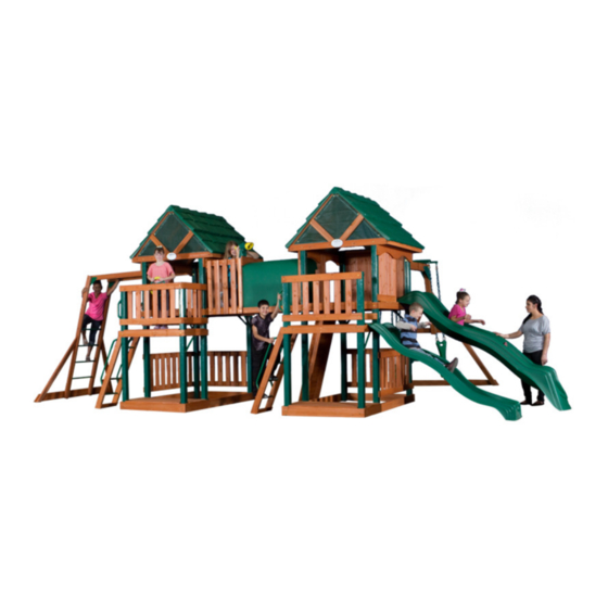
YOU MUST START HERE!
Use these assembly instructions to begin assembly of your Cedar Mountain swingset.
7.
DO NOT INSTALL THE 10' SLIDE AND THE 8' SLIDE NEXT TO EACH OTHER! YOU
MUST LEAVE A TOWER WALL PANEL IN PLACE AS A SPACER TO SEPARATE THE
TWO SLIDES. MOUNTING THEM CLOSE WILL CAUSE A PLAY CONFLICT AND
MAY RESULT IN INJURY!
8.
DO NOT MOUNT THE MONKEY BARS ON THE SAME TOWER/SIDE OF THE
TOWER AS EITHER SLIDE. THIS WILL CAUSE A PLAY CONFLICT AND MAY RESULT
IN INJURY!
except for the Tunnel.
Meijer.com
Advertisement
Table of Contents

Subscribe to Our Youtube Channel
Related Manuals for Backyard Discovery Next Generation 5007


Summary of Contents for Backyard Discovery Next Generation 5007
- Page 1 Meijer.com YOU MUST START HERE! Use these assembly instructions to begin assembly of your Cedar Mountain swingset. except for the Tunnel. DO NOT INSTALL THE 10’ SLIDE AND THE 8’ SLIDE NEXT TO EACH OTHER! YOU MUST LEAVE A TOWER WALL PANEL IN PLACE AS A SPACER TO SEPARATE THE TWO SLIDES.
-
Page 2: Your Warranty
Meijer.com Next MODEL #5007 ASSEMBLY MANUAL Generation YOUR WARRANTY Leisure Time Products Inc, provides a 5- year pro-rate warranty. See inside back cover of this manual for details. We take great care to design our products with your child's safety in mind. However, only with careful supervision and proper safety instructions, can you be assured of safe play time on any product designed for... - Page 3 Meijer.com...
- Page 4 We recommend that you apply a wood ends. sealant or protectant at the time of SEE PAGES 34 THRU 36 FOR MAINTENANCE TIPS Page 1 - SAFETY & ASSEMBLY INFO Next Generation 5007 10-0409 Version 4 © Leisure Time Products Inc.
- Page 5 At this time and always, review the "safety and general information - cautions for use" sections with each child using the play product. Page 2 - SAFETY & ASSEMBLY INFO Next Generation 5007 10-0409 Version 4 © Leisure Time Products Inc.
- Page 6 Sheridan, OR 97378 Preservative: Pacbor Treated (Disodium Octaborate Tetrahydrate) Retention level: .118 pcf Wood species: Pine, White Fir, Hem Fir, and/or Doug Fir Page 3 - SAFETY & ASSEMBLY INFO Next Generation 5007 10-0409 Version 4 © Leisure Time Products Inc.
-
Page 7: Safety & Assembly
A FALL ON TO A HARD SURFACE COULD RESULT IN SERIOUS INJURY Any edging used to contain the ground must be beyond the safe play area. (Ex. Landscape timbers or railroad ties) Page 4 - SAFETY & ASSEMBLY Next Generation 5007 10-0409 Version 4 © Leisure Time Products Inc. - Page 8 Meijer.com Page 5 - SAFETY & ASSEMBLY Next Generation 5007 10-0409 Version 4 © Leisure Time Products Inc.
-
Page 9: Using The Hardware
DO NOT over tighten there are no protruding sharp edges. wood and then use a ½" AND CAUSE AND CAUSE SPLINTERING SPLINTERING socket to tighten. Page 6 - USING THE HARDWARE Next Generation 5007 10-0409 Version 4 © Leisure Time Products Inc. - Page 10 Meijer.com Page 7 - PART LOCATOR Next Generation 5007 10-0409 Version 4 © Leisure Time Products Inc.
- Page 11 1 x 3-1/2 x 20 [ 2.54 x 8.89 x 50.80 ] 1 x 3-1/2 x 24 [ 2.54 x 8.89 x 60.96 ] Page 8 - WOODEN PARTS C1 - H14 Next Generation 5007 10-0409 Version 4 © Leisure Time Products Inc.
- Page 12 O1 Tent Cleat * 4 Holes * 4 Req (W100047) 11/16 x 1-1/2 x 4-1/4 [16 x 38 x 108] 11/16 x 1-1/2 x 36-5/8 [16 x 38 x 930] Page 9 - WOODEN PARTS J1 - 02 © Leisure Time Products Inc. Next Generation 5007 10-0409 Version 4...
- Page 13 Page 11 and take special care to note the sizes given in each step. See page 6 for proper installation instructions. Page 10 - HEX HEAD BOLTS SCREWS & WASHERS © Leisure Time Products Inc. Next Generation 5007 10-0409 Version 4...
-
Page 14: Additional Items
1 - METAL ID PLAQUE 4 - GROUND STAKES 1 - ASSEMBLY MANUAL 1 - POUNDING BLOCK 4 - Y28 15 1/4" METAL DOWELS Page 11 - FASTENER DETAIL LIST & MISC. PARTS Next Generation 5007 10-0409 Version 4 © Leisure Time Products Inc. - Page 15 Tooth Lock Washers , Flat Washers and Spike attach H3, again noting single hole toward C2 Post, T Nut. using 5/16 x 3-3/4” Hex Bolt, Internal Tooth Lock Washers and Flat Washers Page 12 Next Generation 5007 10-0409 Version 4 © Leisure Time Products Inc.
- Page 16 BOLT STEP 6 Attach Right Floor Rail H7 to C3 Post using 5/16 x 3-3/4” Hex Bolts, Internal Tooth Lock Washers, Flat Washers and Spike T Nut. Page 13 © Leisure Time Products Inc. Next Generation 5007 10-0409 Version 4...
- Page 17 BOLT STEP 8 Attach H8 Floor Rail, four-hole, to C1 Post using 5/16 x 3-3/4” Hex Bolts, Internal Tooth Lock Washers, Flat Washers and Spike T Nut. Page 14 Next Generation 5007 10-0409 Version 4 © Leisure Time Products Inc.
- Page 18 G1 Baseboards, pilot drill with 3/16"bit using holes in G5 as guide and attach using 5/16x2-1/2” Lag Screws, Internal Tooth Lock Washers and Flat Washers. Page 15 © Leisure Time Products Inc. Next Generation 5007 10-0409 Version 4...
- Page 19 Left side of C1 Post, pilot drill with 3/16" bit using holes in G7 as a guide. Attach using 2-1/2” Lag Screws, Internal Tooth Lock Washers and Flat Washers. Page 16 Next Generation 5007 10-0409 Version 4 © Leisure Time Products Inc.
- Page 20 STEP 14 Attach H4 Top Floor Joist between H6 Left Floor Rail and H7 Right Floor Rail using four 2-1/2” Wood Screws. Note: Center screws into H7. Page 17 Next Generation 5007 10-0409 Version 4 © Leisure Time Products Inc.
- Page 21 2-1/2” Lag Screws, Internal Tooth Lock Washers and Flat Washers. STEP 17 At this point, place the Y18 Plastic Post Caps on all six of the Tower Posts. Page 18 Next Generation 5007 10-0409 Version 4 © Leisure Time Products Inc.
- Page 22 STEP 20 On Upper Floor place M3, five-hole Floor Boards, seven on each side of N1 Center Floor Board, and space evenly. Then attach using 2” Wood Screws. Page 19 Next Generation 5007 10-0409 Version 4 © Leisure Time Products Inc.
- Page 23 C1 Posts. Then attach G2 Sculptured Rails to front and back of C2 and C1 Posts using 5/16 x 3-3/4” Hex Bolts, Internal Tooth Lock Washers and Flat Washers. Page 20 Next Generation 5007 10-0409 Version 4 © Leisure Time Products Inc.
- Page 24 Left and Right Floor Rail on Bottom Floor and between C3 Posts. At this point, install Lower Deck Floor Boards, M3, using 2” Wood Screws spacing fifteen M3 Floor Boards evenly. Page 21 Next Generation 5007 10-0409 Version 4 © Leisure Time Products Inc.
- Page 25 Attach M5, four-hole, Clubhouse Rail at C1 Post above Lower and Top Deck; measuring 2-1/4” up from top of M3 Floor Board mark C1 Post. Attach using 2” Wood Screws. Page 22 Next Generation 5007 10-0409 Version 4 © Leisure Time Products Inc.
- Page 26 1-1/2” Wood Screws. Now in the pre-drilled holes on M8 Wall Rails attach to C-Posts with 2-1/2” Wood Screws. Repeat G8 and M8 process on back of tower. Page 23 Next Generation 5007 10-0409 Version 4 © Leisure Time Products Inc.
- Page 27 N4 Cross Brace * 4 Holes * 2 Req (W100043) 11/16 x 2-3/8 x 30-7/8 [16 x 60 x 784] #8 X 1-1/8" WOOD SCREW #8 X 3/4 " WASHER HEAD SCREW Page 24 Next Generation 5007 10-0409 Version 4 © Leisure Time Products Inc.
- Page 28 Hold Tent Top tight underneath and attach SC1 Tent Cleat using 1-1/4" Wood Screws. Would be best if you have help to hold the Tent taunt when adding Cleat then fold tent top over Cleat and screw Cleat through the grommets using 3/4” Washer Head Screws. Page 25 Next Generation 5007 10-0409 Version 4 © Leisure Time Products Inc.
- Page 29 Washers and Flat Washers to Tower Legs, making sure that the H5 Roof Support is centered and flush with the top of the leg. 5/16" FLAT WASHER 5/16" INTERNAL TOOTH LOCK WASHER 5/16 X 2-1/2" SCREW Page 26 Next Generation 5007 10-0409 Version 4 © Leisure Time Products Inc.
- Page 30 Top of G2 and flush with end of M7 Window Trim and fasten with 1-1/2” Wood Screws; finish by fastening top of Wall Boards N3 and M10s to M7, using 1/1/4” Wood Screws. Front Page 27 Next Generation 5007 10-0409 Version 4 © Leisure Time Products Inc.
- Page 31 Washers and Flat Washers. Make sure that H9 is flush with outside of C3. Now attach six M9 Wall Boards to H9 Wall Rails on right side of Tower spacing approximately 2-3/4” apart using 1-1/2” Wood Screws. Page 28 Next Generation 5007 10-0409 Version 4 © Leisure Time Products Inc.
- Page 32 24" from G1 Baseboard and mark Post again. Place bottom of M1 Rail with mark and attach to C2 and C1 Posts using 2” Wood Screws. Front Page 29 Next Generation 5007 10-0409 Version 4 © Leisure Time Products Inc.
- Page 33 WOOD #8 X 2" SCREW WOOD SCREW STEP 45 Attach six M9 Wall Boards to inside of M4 Wall Rails approximately 2-3/4” apart using 1-1/4” Wood Screws. Page 30 Next Generation 5007 10-0409 Version 4 © Leisure Time Products Inc.
- Page 34 Entry Ladder Rails are 16” apart outside to outside. Then attach M11 Entry Ladder Back to inside of Ladder Rails measuring up from bottom 1/8” and fastening with 2” Wood Screws. 16" Page 31 Next Generation 5007 10-0409 Version 4 © Leisure Time Products Inc.
- Page 35 Now use hole in bottom of handle as guide to pilot drill and finish attaching with 2 ½” lag screw, lock washer and flat washer. Page 32 Next Generation 5007 10-0409 Version 4 © Leisure Time Products Inc.
- Page 36 Your Lowe's 5007 Next Generation Tower is now finished. Here is a layout for Accessories that you may add to your Tower which can be purchased at your Lowe's Stores. Page 33 Next Generation 5007 10-0409 Version 4 © Leisure Time Products Inc.
-
Page 37: Maintenance
Please dispose of the unit in such a way that no unreasonable hazards will exist (sharp edges, broken parts, and exposed screws) at the time it is discarded. Page 34 - MAINTENANCE © Leisure Time Products Inc. Next Generation 5007 10-0409 Version 4... -
Page 38: Commonly Asked Questions And Answers
However, if rocks or roots surface under the base support pieces, these protrusions must be removed or the play product relocated to another area in order to eliminate rocking. Page 35 - MAINTENANCE Next Generation 5007 10-0409 Version 4 © Leisure Time Products Inc. - Page 39 Question: Who can I hire to assemble my playset? Answer: We do not suggest assemblers. Please refer to your yellow pages or ask for a recommendation from where you purchased your playset. Page 36 - MAINTENANCE Next Generation 5007 10-0409 Version 4 © Leisure Time Products Inc.
-
Page 40: For Your Records
SUPERVISED AT ALL TIMES. Special Note: We reserve the right to make changes in material and design without notice. PARENT/OWNER __________________________________________________________ DATE ____________________________________________________________________ WARRANTY COMMENTS: ______________________________________________________________ Next Generation 5007 10-0409 Version 4 © Copyright Leisure Time Products, Inc. _________________________________________________________________________... -
Page 41: Warranty Registration Card
Meijer.com MODEL #5007 ASSEMBLY MANUAL LEISURE TIME PRODUCTS Next Generation DETACH HERE AND MAIL WARRANTY REGISTRATION CARD LEISURE TIME PRODUCTS, INC. P.O. Box 459 Siloam Springs, AR 72761 1-866-362-1123 Toll Free Office hours: 7am - 4pm, Mon-Fri, Central Time... - Page 42 Meijer.com Part # 50 17 Next Generation PLASTIC ROOF ASSEMBLY INSTRUCTIONS H2 Tent Support * 4 Holes * 1 Req H1 Roof Support * 4 Holes * 2 Req H10 Upright * 2 Holes * 2 Req 1 x 3-1/2 x 59-1/2 [ 2.54 x 8.89 x 151.13 ] 1 x 3-1/2 x 59-1/2 [ 2.54 x 8.89 x 151.13 ] 1 x 3-1/2 x 29-1/2 [ 2.54 x 8.89 x 74.93 ] TENT TOP...
- Page 43 Meijer.com #8 X 2-1/2 " WOOD SCREW STEP 2 Now attach two F1 Roof Rafters together, flushing points, and fasten together using 2-1/2” Wood Screws. Then repeat on three more sets of Rafters STEP 3 Now replace H1s on Set and note the next process will take at least two people.
- Page 44 Meijer.com (R2) ROOF PANEL (R1) Roof Sub Panel #8 X 3/4 " STEP 4 WASHER HEAD Now attach White Roof Sub- SCREW 1-1/2" Panels R1 to F1 Rafter OVERLAP Assemblies overlapping the left and right of Clubhouse approximately 1-1/2”. Note: The Sub-Roof Panel will hang down over H1 Roof Rail so that Sub-Roof Panel will be flush at...
- Page 45 Meijer.com (R2) ROOF PANEL (R3) RIDGE CAP STEP 6 At this point, measure up from bottom 19-1/2” and again attach next panel using 1-1/2” Green Washer Head Screws and Green Now repeat Green Washers. Roof Panels on opposite side of Roof. 19-1/2"...
- Page 46 Meijer.com #8 X 3/4 " WASHER HEAD SCREW STEP 8 Mesh Panels will be installed using 3/4” Washer Head Screws. It will probably take two people. Start at top. Place two screws and pull evenly down on F1 Rafters and then attach to top of H5 Rail. #8 X 1-1/2 "...
-
Page 47: Instrucciones De Ensamblaje
Meijer.com Part e # 50 17 TECHO PLASTICO Última Generación INSTRUCCIONES DE ENSAMBLAJE H2 soporte de la cubierta * 4 agujeros * 1 Req H1 soporte del techo * 4 agujeros * 2 Req H10 Paral * 2 agujeros * 2 Req 1 x 3-1/2 x 59-1/2 [ 2,54 x 8,89 x 151,13 ] 1 x 3-1/2 x 59-1/2 [ 2,54 x 8,89 x 151,13 ] 1 x 3-1/2 x 29-1/2 [ 2,54 x 8,89 x 74,93 ]... - Page 48 Meijer.com TORNILLOS PARA MADERA No. 8 x 2-1/2 in. (6,3 cm) PASO 2 Ahora fije juntos dos cabrios de techo F1, con los puntos a ras y asegúrelos utilizando tornillos de madera de 2-1/2 in. (6,3 cm). Luego repita en tres juegos más de cabrios. PASO 3 Ahora reemplace los H1 en el juego y observe que el próximo proceso implicará...
- Page 49 Meijer.com (R2) PANEL DE TECHO (R1) Sub Panel del techo TORNILLO CON CABEZA DE PASO 4 ARANDELA No. 8 x 3/4 in. (1,9 cm) Ahora fije los sub paneles blancos 1-1/2 in. de techo R1 a los ensambles de cabrio F1 superponiendo el OVERLAP izquierdo y el derecho de la casa club aproximadamente 1-3/4 in.
- Page 50 Meijer.com (R2) PANEL DE TECHO (R3) CABALLETE PASO 6 En este punto mida desde la parte inferior hacia arriba 19-1/2 in. (49,5 cm) y de nuevo fije el siguiente panel utilizando tornillos verdes cabeza de arandela de 1- 1/2 in. (3,8 cm) y arandelas verdes.
- Page 51 Meijer.com TORNILLO CON CABEZA DE ARANDELA No. 8 x 3/4 in. (1,9 cm) PASO 8 Los paneles de malla se instalarán utilizando tornillos cabeza de arandela de 3/4 in. (1,9 cm). Probablemente se necesitarán dos personas. Comience en la parte superior. Coloque dos tornillos y hale uniformemente hacia abajo en los cabrios F1 y luego fije a la parte superior del larguero H5.
- Page 52 Meijer.com CEDAR MOUNTAIN TUNNEL ASSEMBLY Model: #55012 Manufacturer: Backyard Discovery 3001 North Rouse Pittsburg, KS 66762 1-800-856-4445 Register your new swing set on-line @ www.swingsetsonline.com (you will also find any updates on assembly instructions and information to order replacement parts) Save this assembly manual for future reference in the event that you need to order replacement parts.
-
Page 53: Parts Identification
Parts Identification Meijer.com Wood Components (NOT TO SCALE) E1 - LEFT TUNNEL RAIL 1 3/8"x3 3/8"x62" (36x86x1574.8) E2 - RIGHT TUNNEL RAIL 1 3/8"x3 3/8"x62" (36x86x1574.8) E3 TUNNEL FLOOR RAIL (NOT USED WITH (2) TOWERS) F1 - LEFT TUNNEL RAIL 1"x2 3/8"x33 7/8"... - Page 54 Parts Identification Meijer.com Wood Components (NOT TO SCALE) M3 - TUNNEL WALL RAIL 5/8"x3 3/8"x23 1/4" (16x86x590.6) M4 - TUNNEL FLOOR BOARD (18) 5/8"x3 3/8"x22" (16x86x558.8) N1 - KNOTCHED TUNNEL SUPPORT 5/8"x2 3/8"x20 1/4" (16x60x514.4) Parts Identification Accessories (NOT TO SCALE) PT2 - PLASTIC TUNNEL 39 x 81 1/8"x38 7/8"x81"...
- Page 55 Meijer.com Parts Identification Hardware AJ - BOLT HEX 5/16x1 1/4 - H100042 BC - SCREW PWH 8x3/4 - H100070 AH - BOLT HEX 5/16x1-1/2 - H100041 (26) TR - BOLT HEX 5/16x1 3/4 - H100043 BG - T-NUT 5/16 - H100074 (11) AL - BOLT HEX 5/16x2 1/2 - H100045 (39)
- Page 56 Meijer.com E1 - LEFT TUNNEL RAIL 1 3/8"x3 3/8"x62" (36x86x1574.8) E2 - RIGHT TUNNEL RAIL Y27 - L BRACKET 2 x 1 x 3 GREEN 1 3/8"x3 3/8"x62" (36x86x1574.8) STEP 1 T-NUT 5/16 (10 PLCS) (10) T-NUT 5/16 STEP 2 NUT LOCK WASHER FLAT 8x19 WASHER...
- Page 57 Meijer.com M4 - TUNNEL FLOOR BOARD 5/8"x3 3/8"x22" (16x86x558.8) STEP 3 SCREW PFH 8x1 3/4 SCREW PFH 8x1 3/4 (8 PLCS) 3/4"...
- Page 58 Meijer.com F1 - LEFT TUNNEL RAIL F2 - RIGHT TUNNEL RAIL 1"x2 3/8"x33 7/8" (24x60x860) 1"x2 3/8"x33 7/8" (24x60x860) F3 - TUNNEL RAIL 1 3/8"x2 3/8"x33 1/8" (36x60x840) STEP 4 BOLT HEX 5/16x2 1/2 WASHER (8 PLCS) (10) FLAT 8x19 WASHER LOCK INT 8x15 (8 PLCS) WASHER FLAT 8x19...
- Page 59 Meijer.com M4 - TUNNEL FLOOR BOARD (16) 5/8"x3 3/8"x22" (16x86x558.8) STEP 5 SCREW PFH 8x1 3/4 SCREW PFH 8x1 3/4 (64 PLCS)
- Page 60 Meijer.com G2 - SCULPTURED TUNNEL RAIL G1 - SCULPTED TUNNEL RAIL 1"x5 1/2"x24 7/8" (24x139.7x630.8) 1"x5 1/2"x24 7/8" (24x139.7x630.8) STEP 6 WASHER FLAT 8x19 WASHER LOCK INT 8x15 LAG SCREW 5/16x2-1/2 BOLT HEX 5/16x3 1/4 T-NUT 5/16 LAG SCREW HEX 5/16x2-1/2 (4 PLCS) WASHER LOCK INT 8x15 (4 PLCS)
- Page 61 Meijer.com M3 - TUNNEL WALL RAIL 5/8"x3 3/8"x23 1/4" (16x86x590.6) STEP 7 SCREW PFH SCREW PFH 8x1 1/2 8x1 1/2 (8 PLCS)
- Page 62 Meijer.com M2 - PICKET 5/8"x3 3/8"x33 1/8" (16x86x840) STEP 8 SCREW PFH 8x1 1/8 (6 PLCS) SCREW PFH (12) 8x1 1/8 SCREW PFH 8x1 1/8 (6 PLCS) 1 7/8" (3 SPCS)
- Page 63 Meijer.com N1 - KNOTCHED TUNNEL SUPPORT 5/8"x2 3/8"x20 1/4" (16x60x514.4) STEP 9 FLUSH FLUSH SCREW PFH (12) 8x1 1/4 FLUSH FLUSH SCREW PFH 8x1 1/4 (12 PLCS) HAND TIGHTEN ALL SCREWS IN THIS STEP.
- Page 64 Meijer.com M1 - KNOTCHED TUNNEL RAIL 5/8"x3 3/8"x36 1/4" (16x86x920.8) STEP 10 SCREW PFH 8x1 3/4 HAND TIGHTEN ALL SCREWS IN THIS STEP. FLUSH SCREW PFH 8x1 3/4 (6 PLCS)
- Page 65 Meijer.com PT2 - PLASTIC TUNNEL 39 x 81 1/8"x38 7/8"x81" (3x987x2058) STEP 11 SCREW PWH 8x3/4 LOOSEN THE 'M1' AND 'N1' NOTCHED BOARDS. SLIDE ONE SIDE OF THE 'PT2' PLASTIC TUNNEL INTO THE GROOVES OF THE VERTICAL 'N1' NOTCHED BOARDS AND DOWN UNTIL THE EDGE OF THE 'PT2' PLASTIC TUNNEL BOTTOMS OUT IN THE GROOVE OF THE HORIZONTAL 'M1' NOTCHED BOARD THEN FINISH...
- Page 66 Meijer.com (1) TUNNEL ASSEMBLY STEP 12 WASHER FLAT 8x19 WASHER LOCK INT BOLT HEX 8x15 5/16x1 1/4 SCREW PFH 8x1 3/4 T-NUT 5/16 BOLT HEX 5/16x1 1/4 (4 PLCS) WASHER LOCK INT 8x15 (4 PLCS) WASHER FLAT 8x19 (4 PLCS) T-NUT 5/16 (4 PLCS) PILOT DRILL HOLES...
- Page 67 Meijer.com STEP 13 WASHER FLAT 8x19 WASHER LOCK INT BOLT HEX 8x15 5/16x1 1/4 SCREW PFH 8x1 1/2 T-NUT 5/16 SCREW PFH BOLT HEX 5/16x1 1/4 (4 PLCS) WASHER LOCK INT 8x15 (4 PLCS) WASHER FLAT 8x19 (4 PLCS) T-NUT 5/16 (4 PLCS) PILOT DRILL HOLES USING 3/8"...
- Page 68 Meijer.com Part # 5077 • 8 Foot Slide Part # 5087 • 10 Foot Slide Next Generation 8 & 10 Foot Slide ASSEMBLY INSTRUCTIONS Note hardware for attaching the slide is included in the 5007 tower kit. The 8ft. slide will require 2 bolts The 10ft.
- Page 69 Meijer.com Part # 50 47 Next Generation MONKEY BAR ASSEMBLY INSTRUCTIONS STEP 1 You will need to remove wall to create opening. The Monkey Bar Add-On will attach to a Sculptured Rail G2 which will be a top rail on the back left of your sets Club House. This space is the recommended location.
- Page 70 Meijer.com STEP 3 Attach the Y40 Bracket to the ends of both Monkey Bar Rails using 2” Hex Head Bolts, Lock Washers, Washers and 5/16” Bracket Lock Nut. Tighten securely but do not over tighten. 5/16 X 2018 NYLOCK LOCK NUT STEP 4 Pound the Metal End Ladder Rungs Y15 into one of the End Ladder Rails E1.
- Page 71 Meijer.com STEP 5 Drill 3/16” pilot hole using the pre-drilled holes in the Monkey Bar Ground Board G1 as guide and attach it to the End Ladder assembly using two 2-1/2” Lag Screws, Lock Washers and Flat Washers. Tighten the screws securely but do not over tighten.
- Page 72 Meijer.com STEP 7 Lay the Monkey Bar assembly and the End 6”Metal Ladder Triangle Brace assembly end to end as shown. Then Connect them with 6” Metal Triangle Brace between them as shown with 3” Hex Head Bolts, Lock Washers, Flat Washers and Spike Tee Nuts and 1- 1/2”...
- Page 73 Meijer.com STEP 9 Turn the Monkey Bar assembly Lag Bolt Hex Bolt Hex Bolt over and put into position. Secure Lag Bolt the Monkey Bar assembly to Sculptured Rail G2 with 1-1/4” Hex Head Bolts, Lock Washers, Flat Washers and Spike T Nuts according to the bolting diagram Drill 3/8”...
-
Page 74: Instrucciones De Ensamblaje
Meijer.com Part e # 50 47 Última Generación PASAMANOS INSTRUCCIONES DE ENSAMBLAJE PASO 1 Deberá retirar la pared para crear una abertura. El Pasamanos se fija a un larguero tallado G2 el cual será un larguero superior en la parte posterior izquierda de la casa club. - Page 75 Meijer.com PASO 3 Fije los soportes Y40 a los extremos de ambos largueros para el pasamanos utilizando pernos cabeza hexagonal de 2 in. (5,1 cm), Soporte arandelas de seguridad, arandelas y la tuerca de seguridad de 5/16 in. (8 mm). Apriete de forma segura pero no demasiado.
- Page 76 Meijer.com DEBE MEDIR 22-1/2in. DE BORDE INTERNO A BORDE INTERNO TORNILLO TIRAFONDO DE 5/16 X 2-1/2 in. (8 mm x 6,3 cm) ARANDELA DE SEGURIDAD DE 5/16 in. (8 mm) ARANDELA PLANA DE 5/16 in. (8 mm) PASO 5 Taladre agujero piloto de 3/16” in. (4,8 mm) utilizando los agujeros pre-taladrados en la tabla de tierra G1 para el pasamanos como guía y fíjela al ensamble de escalera terminal utilizando tornillos tirafondo de 2-1/2 in.
- Page 77 Meijer.com PASO 7 Coloque el ensamble del pasamanos y el ensamble de la escalera terminal hacia el extremo Abrazadera triangular como se ilustra. Luego conéctelos metálica de 6in. (15,2 cm) con la abrazadera triangular de metal de 15,2 cm entre ellos como se ilustra con pernos cabeza hexagonal de 7,6 cm, arandelas de seguridad, arandelas planas y...
- Page 78 Meijer.com PASO 9 Déle vuelta al ensamble del pasamanos y PERNO CABEZA TORNILLO HEXAGONAL PERNO CABEZA colóquelo en posición. Asegure el TIRAFONDO HEXAGONAL TORNILLO ensamble del pasamano al larguero TIRAFONDO tallado G2 con pernos cabeza hexagonal de 3,2 cm, arandelas de seguridad, arandelas planas y tuerca en T con espigas de acuerdo al diagrama que se ilustra más abajo.
- Page 79 Meijer.com Part # 50 3 7 Next Generation SWING BEAM ASSEMBLY INSTRUCTIONS ) Swing Beam * 15 Holes * 3-1/4 x 5-1/4 x 94 SWING HANGER 3/8" INTERNAL STEP 1 TOOTH LOCK WASHER Attach the Swing Hangers to the Swing Beam using two 3/8 x 5-1/2"...
- Page 80 Meijer.com ( E1 ) Long Angle Brace * 1 Hole * 30° - 60° * 1-1/2 x 3-1/2 x 85 ( B1 ) Beam End Post * 3 Holes * 3-1/4 x 3-1/4 x 47 METAL TRIANGLE STEP 2 5/16 X 4" Attach the two Metal Triangles HEAD Y1 to the Swing Beam as shown...
- Page 81 Meijer.com (G1 ) Beam Ground Board * 4 Holes * 1 x 5-1/2 x 89 ( E2 ) Beam End Support * 4 Hole * 1-1/2 x 3-1/2 x 40-3/4 STEP 5 Pilot drill with 3/16" bit using holes in G1 as guide and attach the G1 Beam Ground Board to the assembly using four 2"...
- Page 82 Meijer.com STEP 7 Attach the support assembly to the Swing Beam with the Metal Triangles Y1 using two 4” Hex Head Bolts, Lock Washers, Flat Washers and Lock Nut. 5/16 X 4" HEX HEAD BOLT 5/16" X 2018 NYLOCK LOCK NUT 5/16"...
- Page 83 Meijer.com 5/16” x 2” HEX HEAD BOLT STEP 9 Using the pre-drilled holes in the G4 Club House Wall Rail as a guide, drill thru the Wall Boards using a 3/8” drill bit. Install four 5/16” Spiked T Nuts, from the inside of the Tower, into these holes. Turn over the Swing Beam Assembly, stand it up, and line up the holes in the Y16 Swing Beam Mount to the holes in the G4 Club House Wall Rail.
- Page 84 Meijer.com Part e # 50 3 7 Última Generación BARRA PARA COLUMPIO INSTRUCCIONES DE ENSAMBLAJE COLGADOR DEL COLUMPIO ( A1 ) Barra para columpio * 15 agujeros * 3-1/4 x 5-1/4 x 94 A RANDELA DE SEGURIDAD DE 3/8 PASO 1 in.
- Page 85 Meijer.com ( E1 ) Refuerzo largo en ángulo * 1 agujero * 30° - 60° * 1-1/2 x 3-1/2 x 85 ( B1 ) Poste para extremo de barra * 3 agujeros * 3-1/4 x 3-1/4 x 47 TRIÁNGULO DE METAL PASO 2 PERNO CABEZA HEXAGONAL DE...
- Page 86 Meijer.com (G1 ) Tabla de apoyo A tierra * 4 agujeros * 1 x 5-1/2 x 89 ( E2 ) Soporte de extremo para la barra * 4 agujeros * 1-1/2 x 3-1/2 x 40-3/4 PASO 5 Haga un agujero piloto con la broca de 3/16 in.
- Page 87 Meijer.com PASO 7 Fije el ensamble del soporte a la barra para columpio con los triángulos de metal Y1 utilizando dos pernos cabeza hexagonal de 4 in. (10 cm), arandelas de seguridad, arandelas planas y tuerca de seguridad. P E R N O C A B E Z A H E X A G O N A L D E 5 / 1 6 x 4 in. TUERCA MECÁNICA DE (8 mm x 10 cm)
- Page 88 Meijer.com PERNO CABEZA HEXAGONAL DE 2 in. (5 cm), ARANDELA DE SEGURIDAD DE 5/16 in. (8 mm) TUERCA EN T DE 5/16 in. (8 mm) CON ESPIGA ARANDELA PLANA DE PASO 9 5/16 in. (8 mm) Utilizando los agujeros pre-taladrados en el larguero para pared de la casa club G4 como guía, taladre a través de las tablas de pared utilizando una broca de 3/8 in.
Need help?
Do you have a question about the Next Generation 5007 and is the answer not in the manual?
Questions and answers