Table of Contents
Advertisement
Quick Links
• Owner's Manual
• Frequently Asked Questions
• Assembly Instructions
• Warranty Information
Register your new swing set on-line @ www.swingsetsonline.com
(you will also find any updates on assembly instructions and
Features the
Save this assembly manual for future reference in the event that
INS-6013-A-Sky Fort II-Eng 6/17/13
Manufacturer: Backyard Discovery
3001 North Rouse
Pittsburg, KS 66762
1-800-856-4445
information to order replacement parts)
you need to order replacement parts.
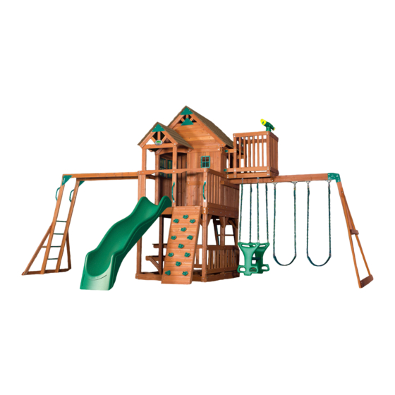
Sky Fort II
Wooden Swing Set
Model: # 6013
fastening system.
Made in China
Advertisement
Table of Contents

Subscribe to Our Youtube Channel
Related Manuals for Backyard Discovery 6013


Summary of Contents for Backyard Discovery 6013
- Page 1 (you will also find any updates on assembly instructions and information to order replacement parts) Features the fastening system. Save this assembly manual for future reference in the event that you need to order replacement parts. Made in China INS-6013-A-Sky Fort II-Eng 6/17/13...
- Page 2 STOP PARE Missing A Part? CALL US BEFORE GOING BACK TO THE STORE! The store where you made your purchase does not stock parts for this item. If you have assembly questions or if you need parts, whether they are missing or damaged Call Toll-Free Help Line or visit www.swingsetsonline.com ¡LLÁMENOS ANTES DE REGRESAR A LA TIENDA! La tienda donde realizó...
- Page 3 Owner’s Manual Play Set Dear Customer: Please read entire booklet completely before beginning the assembly process. Equipment is recommended for use by children 3 to 10 years of age. Structures are not intended for public use. The Company does not warranty any of its residential structures subjected to commercial use such as: Daycare, Preschool, Nursery School, Recreational Park, or any similar Commercial Application.
-
Page 4: Positioning Your Playcenter
Owner’s Manual Play Set Please refer to the Assembly section of the Assembly Manual for Maximum Fall Height. Positioning Your Playcenter 1. The Playcenter is designed to be installed on a level surface by an Adult with an Adult helper. Place in a flat area of your yard to minimize ground preparation. 2. -
Page 5: Operating Instructions
Owner’s Manual Play Set The following chart explains the fall height in feet from which a life threatening head injury would not be expected Critical Heights in feet (m) of Tested Materials Material Uncompressed Depth Compressed Depth 6" (152mm) 9" (228mm) 12"... -
Page 6: Maintenance Instructions
Owner’s Manual Play Set 18. Verify that any suspended climbing ropes, chain, or cable are secured at both ends and that they cannot be looped back on it. 19. Instruct children not to attach items to the playground equipment that are not specifically designed for use with the equipment, such as, but not limited to, jump ropes, clothesline, pet leashes, cables and chain as they may cause a strangulation hazard. -
Page 7: Disposal Instructions
Third Party Assembly: Customer may, in their sole discretion, elect to use a third party person or service to assemble this product. Backyard Discovery assumes no responsibility or liability for any charge incurred by the Customer for any assembly services’. - Page 8 Owner’s Manual Play Set APPENDIX A Information on Playground Surfacing Materials: The following information is from the United States Consumer Product Safety Commission’s Information Sheet for playground surfacing material; also see the following website for additional information: www.cpsc.gov/cpscpub/pubs/323.html. X3. SECTION 4 OF THE CONSUMER PRODUCT SAFETY COMMISSION’S OUTDOOR HOME PLAYGROUND SAFETY HANDBOOK X3.1 Select Protective Surfacing—One of the most important things you can do to reduce the likelihood of serious head injuries is to install shock-absorbing protective surfacing under and around your play equipment.
- Page 9 Owner’s Manual Play Set The American Society for Testing and Materials takes no position respecting the validity of any parent right asserted in connection with any item mentioned in this standard. Users of this standard are expressly advised that determination of the validity of any such parent rights, and the risk of infringement of such rights, are entirely their own responsibility.
- Page 10 The stakes provided should be used to secure it firmly to the ground. 2. What size area is recommended for the playset? Backyard Discovery recommends at least a 6’ (six foot) perimeter around and above the playset for maximum safety. 3. What age range is appropriate for the playsets? Backyard Discovery playsets are recommended for children ages 3 –...
- Page 11 11. The end beam is not straight up and down. Why not? This is normal. Backyard Discovery designs playsets this way to ensure the strongest structure possible. The slight angle adds strength and reduces rocking and twisting.
- Page 12 Tools Required for Installation: (These are the tools that are generally required for assembly of our outdoor products. These tools are not included with the outdoor product purchase.) (Square) (Level 24") (Claw Hammer) (Tape Measure) (Phillips Screw Driver) (Drill Attachments: Phillips Head) (5/16"...
- Page 13 Basic Setup Dimensions Place the set on level ground, not less than 6 ft [2 m] from any structure or obstruction such as a fence, garage, house, overhanging branches, laundry lines, or electrical wires. 21'-11 1/8" [6.7 m] 6'-0" [1.8 m] 16'-9 7/16"...
- Page 14 Parts Identification Wood Components (NOT TO SCALE) A50 - SWING BEAM - W103544 3 3/8"x5 1/4"x89 1/2" (86x134x2274) B1 - TOWER LEG - W103452 3"x3"x89 1/2" (76x76x2274) B2 - TOWER LEG - W103472 3"x3"x89 1/2" (76x76x2274) B3 - TOWER LEG - W103453 3"x3"x83 1/4"...
- Page 15 Parts Identification Wood Components (NOT TO SCALE) E1 - CLUB HOUSE LEG - W103503 1 3/8"x3 3/8"x50 1/2" (36x86x1284) E2 - CLUB HOUSE WALL BOARD - W103512 1 3/8"x3 3/8"x50 1/2" (36x86x1284) E3 - PORCH LEG - W103536 1 3/8"x3 3/8"x50 1/2" (36x86x1282) E4 - ROOF RAFTER - W103519 1 3/8"x3 3/8"x50 3/8"...
- Page 16 Parts Identification Wood Components (NOT TO SCALE) E74 - MONKEY BAR RAIL - W102918 1 3/8"x3 3/8"x77 1/8" (36x86x1959) E79 - MONKEY BAR UPRIGHT - W100995 1 3/8"x3 3/8"x88 1/8" (36x86x2237) F1 - CROWS NEST WALL SUPPORT - W103551 1 3/8"x2 3/8"x37 1/2" (36x60x952) F2 - CROWS NEST WALL SUPPORT - W103554 1 3/8"x2 3/8"x37 1/2"...
- Page 17 Parts Identification Wood Components (NOT TO SCALE) G8 - CLUB HOUSE WALL RAIL - W103502 1"x5 1/4"x50 1/4" (24x134x1277) G9 - BAY WINDOW HEADER - W103516 1"x5 1/4"x45 1/4" (24x134x1150) G50 - GROUND BOARD - W100947 1"x5 1/4"x86 3/4" (24x134x2202) H1 - WALL RAIL - W103487 1"x3 3/8"x80"...
- Page 18 Parts Identification Wood Components (NOT TO SCALE) H10 - PICNIC TABLE SEAT RAIL - W103475 1"x3 3/8"x32" (24x86x812) H11 - CLUB HOUSE WALL RAIL - W103498 1"x3 3/8"x29 7/8" (24x86x758) H12 - PICNIC TABLE SUPPORT - W103476 1"x3 3/8"x28 5/8" (24x86x728) H13 - CROWS NEST FLOOR RAIL - W103547 1"x3 3/8"x27"...
- Page 19 Parts Identification Wood Components (NOT TO SCALE) L1 - CROWS NEST FLOOR BOARD - W103550 5/8"x4 3/8"x27" (16x112x686) L2 - SAND BOX SEAT - W103469 5/8"x4 3/8"x24" (16x112x610) M1 - TOP FLOOR BOARD - W103460 (16) 5/8"x3 3/8"x81 7/8" (16x86x2080) M2 - BOTTOM WALL RAIL - W103470 5/8"x3 3/8"x80"...
- Page 20 Parts Identification Wood Components (NOT TO SCALE) M12 - GABLE BOARD - W103528 5/8"x3 3/8"x45 7/8" (16x86x1166) M13 - PICNIC TABLE TOP - W103482 5/8"x3 3/8"x41 1/2" (16x86x1054) M14 - GABLE BOARD - W103529 5/8"x3 3/8"x39 1/8" (16x86x994) M15 - CROWS NEST WALL RAIL - W103556 5/8"x3 3/8"x38 7/8"...
- Page 21 Parts Identification Wood Components (NOT TO SCALE) M25 - FRONT PORCH ROOF SUPPORT - W103541 5/8"x3 3/8"x30 5/8" (16x86x779) M26 - CROWS NEST WALL RAIL - W103552 5/8"x3 3/8"x30 5/8" (16x86x778) M27 - WALL RAIL - W103537 5/8"x3 3/8"x6 3/8" (16x86x162) M28 - CLUB HOUSE WALL BOARD - W103511 5/8"x3"x27"...
- Page 22 Parts Identification Wood Components (NOT TO SCALE) M73 - REAR SUPPORT - W100610 5/8"x3 3/8"x19 1/4" (16x86x488) M74 - ROCK WALL BOARD - W102998 (10) 5/8"x3 3/8"x21 5/8" (16x86x548) M75 - ROCK WALL BOARD - W103000 5/8"x3 3/8"x21 5/8" (16x86x548) M76 - ROCK WALL BOARD - W102999 5/8"x3 3/8"x21 5/8"...
- Page 23 Parts Identification Wood Components (NOT TO SCALE) N8 - GABLE TRIM - W103531 5/8"x2 3/8"x11 1/2" (16x60x292) N9 - BAY WINDOW TRIM - W103518 (12) 5/8"x2 3/8"x11" (16x60x280) N10 - FRONT PORCH GABLE TRIM - W103543 5/8"x2 3/8"x9 1/2" (16x60x241) N11 - GABLE TRIM - W103532 5/8"x2 3/8"x6 1/2"...
- Page 24 Parts Identification Hardware (23) B - NUT BARREL WH 5/16x5/8 - H100004 (110) D - NUT BARREL WH 5/16x7/8 - H100005 - T-40 Torx Bit - A100042 (14) C - NUT BARREL WH 5/16x1 1/2 - H100006 (101) E - NUT BARREL WH 5/16x1 3/4 - H100007 - T-30 Torx Bit - H100147 (32) Y - LAG SCREW WH 5/16x1 1/2 - H100026...
- Page 25 Parts Identification Hardware (38) K - BOLT WH 5/16x2 - H100012 (18) L - BOLT WH 5/16x2 1/4 - H100013 J - BOLT WH 5/16x1 3/4 - H100011 (94) M - BOLT WH 5/16x2 1/2 - H100014 (50) N - BOLT WH 5/16x2 3/4 - H100015 H - BOLT WH 5/16x1 1/2 - H100010 G - BOLT WH 5/16x1 1/4 - H100009 P - BOLT WH 5/16x3 - H100016...
- Page 26 Parts Identification Hardware BN - SCREW PFH 8x1 - H100085 (26) BE - T-NUT 1/4 - H100072 (31) BG - T-NUT 5/16 - H100074 (393) BR - SCREW PFH 8x1 1/8 - H100088 BQ - SCREW PFH 8x1 1/4 - H100087 (545) BP - SCREW PFH 8x1 1/2 - H100086 (10)
- Page 27 Parts Identification Hardware (26) AZ - BOLT PTH 1/4x1 1/4 - H100062 CY - SCREW PWH 8x5/8 - H100128 (36) BC - SCREW PWH 8x3/4 - H100070 (26) DA - SCREW PWF 10x1/2 - H100132 BJ - SCREW TAPPING 14x1 - H100080 NX - SCREW TAPPING 14x2-1/2 - H100082 YK - BOLT WH 5/16x3/4 - H100222...
- Page 28 Parts Identification Accessories (NOT TO SCALE) DW - SLIDE SUPPORT TUBE 21.34x505 -A100034 HN - PLASTIC WINDOW BYD GREEN DJ - GLIDER ARM LIGHT GREEN - A100021 -A100010 DN - GLIDER SEAT DARK GREEN -A100025 DT - SLIDE RAIL 10' TOP LEFT GREEN - A100032 TR - SLIDE RAIL 10' TOP RIGHT GREEN - A100033 DS - SLIDE RAIL 10' BOTTOM RIGHT GREEN - A100031 DR - SLIDE RAIL 10' BOTTOM LEFT GREEN - A100030...
- Page 29 Parts Identification Accessories (NOT TO SCALE) DP - SWING SEAT GREEN -A100027 EC - METAL RUNG 559 DE - TRIANGLE PLATE 90 5 HOLE BYD GREEN - A100011 -A100045 FA - QUICK LINK EV - CLIMBING ROCK - GREEN (12) -A100069 -A100064 ED - SINGLE DUCTILE HANGER...
- Page 30 Parts Identification Accessories (NOT TO SCALE) TB - SWING BEAM EXTENSION BRACKET-LEFT - A100325 TC - SWING BEAM EXTENSION BRACKET-RIGHT - A100326 KC - METAL GROUND STAKE BROWN - A100178 SQ - "A" REVISION TAG - A100314...
- Page 31 A50 - SWING BEAM - W103544 3 3/8"x5 1/4"x89 1/2" (86x134x2274) TB - SWING BEAM EXTENSION BRACKET-LEFT - A100325 TC - SWING BEAM EXTENSION BRACKET-RIGHT - A100326 5 FT SWING BEAM EXTENDED STEP 1 NOTE: COUNTERSINK TO THE TOP. BOLT WH 5/16x3 NUT BARREL WH 5/16x7/8...
- Page 32 SP50 - SWING BEAM SUPPORT - W103545 E51 - ANGLE BRACE - W100948 3 3/8"x3 3/8"x48 3/8" (86x86x1228) 1 3/8"x3 3/8"x88 3/4" (36x86x2254) E50 - END SUPPORT - W100949 G50 - GROUND BOARD - W100947 1 3/8"x3 3/8"x44 1/8" (36x86x1120) 1"x5 1/4"x86 3/4"...
- Page 33 STEP 3 BOLT WH 5/16x3 NUT BARREL WH 5/16x7/8 SP50 BOLT WH 5/16x3 (2 PLCS) SP50 NUT BARREL WH 5/16x7/8 (2 PLCS)
- Page 34 ED - SINGLE DUCTILE HANGER - A100046 STEP 4 WASHER LOCK INT 10x18 WASHER FLAT 11x25 BOLT HEX 3/8x5-3/4 T-NUT 3/8 T-NUT 3/8 (2 PLCS x 4) WASHER FLAT 11x25 (2 PLCS x 4) WASHER LOCK INT 10x18 (2 PLCS x 4) BOLT HEX 3/8x5-3/4 (2 PLCS x 4)
- Page 35 M70 - SLIDE BED SUPPORT - W100935 DX - SLIDE BED 10' LIGHT GREEN - A100035 5/8"x3 3/8"x19 7/8" (16x86x505) 10 FOOT SLIDE ASSEMBLY PHASE 1 STEP 1 BOLT WH 5/16x1/2 ATTACH SLIDE BED SUPPORT TO SLIDE USING HARDWARE SHOWN. WASHER LOCK EXT 12x19...
- Page 36 DS - SLIDE RAIL 10' BOTTOM RIGHT GREEN - A100031 TR - SLIDE RAIL 10' TOP RIGHT GREEN - A100033 DT - SLIDE RAIL 10' TOP LEFT GREEN - A100032 DR - SLIDE RAIL 10' BOTTOM LEFT GREEN - A100030 10 FOOT SLIDE ASSEMBLY PHASE 2 STEP 2...
- Page 37 DW - SLIDE SUPPORT TUBE 21.34x505 - A100034 21.34 OD x 2.77 W x 505 10 FOOT SLIDE ASSEMBLY PHASE 3 STEP 3 PLACE (1) SLIDE RAIL ASSEMBLY ON A FLAT SURFACE AND BEGIN INSERTING SLIDE BED AT THE BOTTOM OF THE SLIDE RAIL (FIG. 1). HAVE A HELPER BEND THE SLIDE BED TOWARDS THE TOP OF THE SLIDE AND INSERT THE BED INTO THE SLIDE CAVITY.
- Page 38 10 FOOT SLIDE ASSEMBLY PHASE 4 STEP 4 ONCE THE SLIDE BED, SUPPORT TUBES, AND SUPPORT BOARD ARE COMPLETELY IN THE CAVITY AND SUPPORT POCKET, SECURE USING 3" SCREWS AT EACH OF THE PILOT HOLE LOCATIONS AS SHOWN. REPEAT PROCESS FOR OPPOSITE SLIDE RAIL. SCREW PFH (38) SCREW PFH 8x3...
- Page 39 E74 - MONKEY BAR RAIL - W102918 1 3/8"x3 3/8"x77 1/8" (36x86x1959) TZ - L BRACKET 2.5x38x50x55 - A100340 QZ - TRIANGLE PLATE 100 5 HOLE - A100294 5 FT. MONKEY BAR KIT - 8 RUNG STEP 1 WASHER FLAT 8x27 BOLT WH 5/16x2 WASHER FLAT 8x27...
- Page 40 E79 - MONKEY BAR UPRIGHT - W100995 1 3/8"x3 3/8"x88 1/8" (36x86x2237) STEP 2 BOLT WH 5/16x1-1/2 T-NUT 5/16 (4 PLCS) T-NUT 5/16 BOLT WH 5/16x1-1/2 (4 PLCS)
- Page 41 EC - METAL RUNG 559 - A100045 STEP 3 LAG SCREW (16) WH 1/4x1-1/2 LAG SCREW WH 1/4x1-1/2 (16 PLCS)
- Page 42 H82 - MONKEY BAR GROUND BOARD - W100994 1"x3 3/8"x70 3/8" (24x86x1786) H81 - MONKEY BAR BRACE - W100993 1"x3 3/8"x53 1/4" (24x86x1352) STEP 4 BOLT WH 5/16x1-1/2 LAG SCREW WH 5/16x2 BOLT HEX 5/16x2-3/4 NUT BARREL WH 5/16x7/8 T-NUT 5/16 WASHER LOCK INT 8x15...
- Page 43 FX - HAND GRIP METAL GREEN 381 c/c - A100118 STEP 5 LAG SCREW WH 1/4x1 LAG SCREW WH 1/4x1 (4 PLCS)
- Page 44 E73 - RIGHT RAIL - W100037 M74 - ROCK WALL BOARD - W102998 (10) 1 3/8"x3 3/8"x61 3/4" (36x86x1570) 5/8"x3 3/8"x21 5/8" (16x86x548) M75 - ROCK WALL BOARD - W103000 5/8"x3 3/8"x21 5/8" (16x86x548) M76 - ROCK WALL BOARD - W102999 E72 - LEFT RAIL - W100036 1 3/8"x3 3/8"x61 3/4"...
- Page 45 M106 - ROCK WALL END BOARD - W103001 5/8"x3 3/8"x22 7/8" (16x86x580) STEP 2 M106 SCREW PFH 8x1 1/2 SCREW PFH 8x1 1/2 M106...
- Page 46 (12) EV - CLIMBING ROCK - GREEN - A100064 STEP 3 BOLT PTH (24) 1/4x1 1/4 WASHER (24) LOCK INT 8x15 (24) T-NUT 1/4 BOLT PTH 1/4x1 1/4 WASHER LOCK INT 8x15 T-NUT 1/4...
- Page 47 5 Ft Ladder Phase 1 & 2 Phase Notes QTY. DESCRIPTION LABEL • Assemble with hardware as shown. LEFT UPRIGHT • Center rungs in rail grooves. LADDER RUNG SCREW PFH 8x2 SCREW PFH 8x2 SCREW PFH 8x2 QTY. DESCRIPTION LABEL RIGHT UPRIGHT SCREW PFH 8x2...
- Page 48 5 Ft Ladder Phase 3 Phase Notes • Assemble with hardware as shown. SCREW PFH 8x2 LAG SCREW WH 1/4x1-1/2 HAND GRIP GREEN 816 c/c QTY. DESCRIPTION LABEL REAR SUPPORT SCREW PFH 8x2 HAND GRIP 816 C/C LAG SCREW WH 1/4x1-1/2...
- Page 49 STEP 1 T-NUT 5/16 (15) T-NUT 5/16 (2 PLCS) T-NUT 5/16 (3 PLCS) T-NUT 5/16 (2 PLCS) T-NUT 5/16 T-NUT 5/16 (2 PLCS x 2) (2 PLCS) T-NUT 5/16 (2 PLCS)
- Page 50 B1 - TOWER LEG - W103452 3"x3"x89 1/2" (76x76x2274) G1 - TOP FLOOR RAIL - W103455 1"x5 1/4"x80" (24x134x2032) B3 - TOWER LEG - W103453 3"x3"x83 1/4" (76x76x2114) G2 - BOTTOM FLOOR RAIL - W103456 1"x5 1/4"x80" (24x134x2032) B4 - TOWER LEG - W103454 3"x3"x59"...
- Page 51 B2 - TOWER LEG - W103472 G3 - TOP FLOOR RAIL - W103457 3"x3"x89 1/2" (76x76x2274) 1"x5 1/4"x80" (24x134x2032) B5 - TOWER LEG - W103471 3"x3"x59" (76x76x1500) G2 - BOTTOM FLOOR RAIL - W103456 1"x5 1/4"x80" (24x134x2032) B6 - TOWER LEG - W103474 3"x3"x59"...
- Page 52 H5 - FRONT WALL RAIL - W103485 G4 - FLOOR RAIL - W103458 G5 - FLOOR RAIL - W103459 1"x3 3/8"x60 1/2" (24x86x1537) 1"x5 1/4"x60 1/2" (24x134x1537) 1"x5 1/4"x60 1/2" (24x134x1537) STEP 4 WASHER (16) LOCK EXT 12x19 NUT BARREL (16) WH 5/16x1-3/4 WASHER...
-
Page 53: Table Of Contents
H12 - PICNIC TABLE SUPPORT - W103476 G6 - FLOOR JOIST - W103462 G7 - FLOOR RAIL - W103477 1"x3 3/8"x28 5/8" (24x86x728) 1"x5 1/4"x60 1/2" (24x134x1537) 1"x5 1/4"x60 1/2" (24x134x1537) STEP 5 NUT BARREL WH 5/16x1-3/4 WASHER LOCK EXT 8x19 (4 PLCS) (4 PLCS) WASHER LOCK EXT 12x19... - Page 54 M16 - BOTTOM FLOOR BOARD - W103465 L2 - SAND BOX SEAT - W103469 Y3 - BOTTOM FLOOR BOARD - W103466 (16) 5/8"x3 3/8"x35 1/2" (16x86x902) 5/8"x4 3/8"x24" (16x112x610) 5/8"x4"x35 1/2" (16x102x902) STEP 6 SCREW PFH (96) 8x1-1/2 SCREW PFH 8x1-1/2 (88 PLCS) SCREW PFH 8x1-1/2 (8 PLCS)
-
Page 55: Washer Lock Ext 8X19
H4 - PICNIC TABLE RAIL - W103479 M4 - BOTTOM WALL RAIL - W103473 M30 - BOTTOM WALL BOARD - W103484 1"x3 3/8"x67 1/4" (24x86x1708) 5/8"x3 3/8"x60 1/2" (16x86x1537) 5/8"x3 3/8"x21 3/8" (16x86x544) STEP 7 3 1/16" (9 SPCS) BOLT WH 5/16x2-1/4 BOLT WH 5/16x2-1/2... - Page 56 M2 - BOTTOM WALL RAIL - W103470 M30 - BOTTOM WALL BOARD - W103484 (10) 5/8"x3 3/8"x80" (16x86x2032) 5/8"x3 3/8"x21 3/8" (16x86x544) STEP 8 SCREW PFH 8x1 1/8 WASHER (40 PLCS) LOCK EXT 12x19 WASHER BOLT WH LOCK EXT 5/16x2 1/4 8x19 SCREW PFH (40)
- Page 57 E7 - PICNIC TABLE BRACE - W103481 H10 - PICNIC TABLE SEAT RAIL - W103475 1 3/8"x3 3/8"x17 1/2" (36x86x444) 1"x3 3/8"x32" (24x86x812) STEP 9 USING "H10" PICNIC TABLE SEAT RAIL AS A TEMPLATE, MARK AND DRILL A 7/16" OR 10MM THROUGH HOLE IN M30 BOLT WH NUT BARREL PICKET.
-
Page 58: Bolt Wh 5/16X1-1/2
E7 - PICNIC TABLE BRACE - W103481 H10 - PICNIC TABLE SEAT RAIL - W103475 1 3/8"x3 3/8"x17 1/2" (36x86x444) 1"x3 3/8"x32" (24x86x812) STEP 10 BOLT WH 5/16x1-1/2 (1 PLC) WASHER LOCK EXT 8x19 NUT BARREL (1 PLC) BOLT WH WH 5/16x7/8 5/16x1-1/2 NUT BARREL... - Page 59 H9 - PICNIC TABLE SEAT - W103478 1"x3 3/8"x35 1/2" (24x86x902) STEP 11 SCREW PFH (16) SCREW PFH 8x2 (8 PLCS) SCREW PFH 8x2 (8 PLCS)
-
Page 60: Washer Lock Ext
M33 - PICNIC TABLE TOP SUPPORT - W103499 M17 - CENTER PICNIC TABLE TOP - W103483 M13 - PICNIC TABLE TOP - W103482 5/8"x3 3/8"x16" (16x86x406) 5/8"x3"x35 1/2" (16x76x902) 5/8"x3 3/8"x41 1/2" (16x86x1054) H16 - PICNIC TABLE TOP SUPPORT - W103480 1"x3 3/8"x16 1/2"... -
Page 61: Screw Pfh
H17 - TOP FLOOR SUPPORT - W103463 1"x3 3/8"x3" (24x86x76) STEP 13 FLUSH SCREW PFH 8x2 (2 PLCS) SCREW PFH SCREW PFH 8x2 (2 PLCS) SCREW PFH 8x2 (2 PLCS) SCREW PFH 8x2 (2 PLCS) - Page 62 E6 - DECK BRACE - W103464 1 3/8"x3 3/8"x20" (36x86x508) STEP 14 WASHER LOCK EXT 8x19 (12 PLCS) BOLT WH 5/16x2 (12 PLCS) BOLT WH (12) BOLT WH 5/16x2 5/16x2-1/4 LAG SCREW NUT BARREL (12) WH 5/16x2-1/2 WH 5/16x7/8 WASHER WASHER (24) (12)
- Page 63 G6 - FLOOR JOIST - W103462 G5 - FLOOR RAIL - W103459 1"x5 1/4"x60 1/2" (24x134x1537) 1"x5 1/4"x60 1/2" (24x134x1537) STEP 15 BOLT WH 5/16x3-3/4 (2 PLCS) WASHER LOCK EXT 8x19 (2 PLCS) SCREW PFH 8x2-1/2 (4 PLCS) SCREW PFH 8x2-1/2 (4 PLCS) NUT BARREL WH 5/16x1-3/4...
- Page 64 M1 - TOP FLOOR BOARD - W103460 Y2 - TOP FLOOR BOARD - W103467 (16) 5/8"x3 3/8"x81 7/8" (16x86x2080) 5/8"x4"x39 1/2" (16x102x1002) Y4 - TOP FLOOR BOARD - W103468 Y1 - TOP FLOOR BOARD - W103461 5/8"x4"x35 1/2" (16x102x902) 5/8"x4"x78" (16x102x1980) STEP 16 SCREW PFH (135)
- Page 65 M27 - WALL RAIL - W103537 E3 - PORCH LEG - W103536 5/8"x3 3/8"x6 3/8" (16x86x162) 1 3/8"x3 3/8"x50 1/2" (36x86x1282) TZ - L BRACKET 2.5x38x50x55 - A100340 STEP 17 MARK AND DRILL A 7/16" OR 10MM HOLE TO ATTACH 'TZ' BRACKET TO FORT DECK. BOLT WH 5/16x1/2 BOLT WH...
- Page 66 B7 - FRONT LEFT CLUB HOUSE CORNER - W103486 M11 - CLUB HOUSE WALL RAIL - W103496 3"x3"x53 7/8" (76x76x1370) 5/8"x3 3/8"x50 1/4" (16x86x1277) B8 - BACK LEFT CLUB HOUSE CORNER - W103488 M21 - CLUB HOUSE WALL RAIL - W103497 TZ - L BRACKET 2.5x38x50x55 - A100340 3"x3"x53 7/8"...
- Page 67 B9 - FRONT RIGHT CLUB HOUSE CORNER - W103490 M3 - TOP WALL RAIL - W103500 5/8"x3 3/8"x80" (16x86x2032) 3"x3"x53 7/8" (76x76x1370) H11 - CLUB HOUSE WALL RAIL - W103498 B10 - BACK RIGHT CLUB HOUSE CORNER - W103491 1"x3 3/8"x29 7/8" (24x86x758) TZ - L BRACKET 2.5x38x50x55 - A100340 3"x3"x53 7/8"...
- Page 68 H1 - WALL RAIL - W103487 1"x3 3/8"x80" (24x86x2032) STEP 20 BOLT WH 5/16x2-1/2 WASHER LOCK EXT 8x19 WASHER BOLT WH 5/16x3-3/4 LOCK EXT (1 PLC) 12x19 WASHER LOCK EXT 8x19 BOLT WH (1 PLC) 5/16x3-3/4 NUT BARREL WH 5/16x1-3/4 PREVIOUSLY INSTALLED NUT BARREL WH 5/16x1-3/4 T-NUT.
- Page 69 H6 - BACK CLUB HOUSE RAIL - W103489 H2 - WALL RAIL - W103492 1"x3 3/8"x60 1/2" (24x86x1537) 1"x3 3/8"x80" (24x86x2032) STEP 21 WASHER LOCK EXT 8x19 (1 PLC) BOLT WH 5/16x2-1/2 WASHER LOCK EXT 8x19 (1 PLC) (2 PLCS) NUT BARREL BOLT WH 5/16x2-1/2 WH 5/16x1-3/4...
- Page 70 H3 - ROOF SUPPORT RAIL - W103494 H8 - CLUB HOUSE WALL RAIL - W103501 1"x3 3/8"x67 1/4" (24x86x1709) 1"x3 3/8"x50 1/4" (24x86x1277) STEP 22 WASHER LOCK EXT 8x19 (1 PLC) WASHER LOCK EXT 8x19 BOLT WH 5/16x2-1/2 (2 PLCS) (1 PLC) BOLT WH 5/16x2-1/2 (2 PLCS)
- Page 71 H3 - ROOF SUPPORT RAIL - W103494 1"x3 3/8"x67 1/4" (24x86x1709) G8 - CLUB HOUSE WALL RAIL - W103502 1"x5 1/4"x50 1/4" (24x134x1277) H7 - FRONT CLUB HOUSE WALL RAIL - W103495 1"x3 3/8"x60 1/2" (24x86x1537) STEP 23 BOLT WH 5/16x2-1/2 (1 PLC) WASHER LOCK EXT 8x19 (1 PLC)
- Page 72 E2 - CLUB HOUSE WALL BOARD - W103512 B11 - SWING BEAM MOUNT - W103493 1 3/8"x3 3/8"x50 1/2" (36x86x1284) 3"x3"x50 1/4" (76x76x1277) STEP 24 WASHER LOCK EXT 8x19 (2 PLCS) BOLT WH 5/16x2 (2 PLCS) BOLT WH 5/16x2 BOLT WH 5/16x5 WASHER LOCK EXT 8x19 BOLT WH...
- Page 73 M28 - CLUB HOUSE WALL BOARD - W103511 5/8"x3"x27" (16x76x686) M9 - CLUB HOUSE WALL BOARD - W103513 M19 - CLUB HOUSE WALL BOARD - W103514 5/8"x3"x50 1/2" (16x76x1284) 5/8"x3 3/8"x29 7/8" (16x86x758) N1 - CLUB HOUSE WALL BOARD - W103510 5/8"x2 3/8"x50 1/2"...
- Page 74 M22 - WALL BOARD - W103505 (13) 5/8"x3 3/8"x29 7/8" (16x86x758) STEP 26 SCREW PFH (52) 8x1-1/8 SCREW PFH 8x1-1/8 (52 PLCS)
- Page 75 M22 - WALL BOARD - W103505 M6 - CLUB HOUSE WALL BOARD - W103504 M18 - WALL BOARD - W103506 5/8"x3 3/8"x29 7/8" (16x86x758) 5/8"x3 3/8"x53 7/8" (16x86x1370) 5/8"x3 3/8"x27 1/2" (16x86x698) STEP 27 SCREW PFH SCREW PFH 8x1-1/8 (38) 8x1-1/8 (6 PLCS) SCREW PFH 8x1-1/8...
- Page 76 N9 - BAY WINDOW TRIM - W103518 N5 - BAY WINDOW TRIM - W103517 G9 - BAY WINDOW HEADER - W103516 (12) (12) 5/8"x2 3/8"x11" (16x60x280) 5/8"x2 3/8"x20 3/4" (16x60x526) 1"x5 1/4"x45 1/4" (24x134x1150) STEP 28 SCREW PFH 8x1-1/2 (8 PLCS) MARK CENTER OF SCREW PFH 'N9' &...
- Page 77 HN - PLASTIC WINDOW BYD GREEN - A100010 STEP 29 2 7/16" SCREW PWH (24) 8x3/4 7/8" 7/8" 2 7/16" SCREW PWH 8x3/4 (4 PLCS) SCREW PWH 8x3/4 (4 PLCS) SCREW PWH 8x3/4 (4 PLCS)
- Page 78 (2) - BAY WINDOW ASSEMBLY STEP 30 SCREW PFH 8x2 SCREW PFH 8x2 (10 PLCS) (10 PLCS) SCREW PFH (20) BAY WINDOW ASSEMBLY...
- Page 79 E1 - CLUB HOUSE LEG - W103503 M21 - CLUB HOUSE WALL RAIL - W103497 1 3/8"x3 3/8"x50 1/2" (36x86x1284) 5/8"x3 3/8"x30 1/4" (16x86x768) TZ - L BRACKET 2.5x38x50x55 - A100340 STEP 31 MARK AND DRILL A 7/16" OR 10MM HOLE IN DECK BOARD TO SECURE 'TZ' BRACKET TO DECK.
- Page 80 M23 - FRONT WINDOW WALL BOARD - W103508 M8 - CLUB HOUSE WALL BOARD - W103507 M36 - FRONT WINDOW WALL BOARD - W103509 5/8"x3 3/8"x35" (16x86x889) 5/8"x3 3/8"x50 1/2" (16x86x1284) 5/8"x3 3/8"x6 3/8" (16x86x162) STEP 32 SCREW PFH 8x1-1/8 M8 M36 M8 (14 PLCS) SCREW PFH 8x1-1/8...
- Page 81 GK - WINDOW FRAME 216x267 BYD GREEN - A100146 STEP 33 SCREW PWH 8x3/4 (4 PLCS) SCREW PWH 8x3/4 36 1/8" 7/16" WINDOW SCREW LOCATION...
- Page 82 E4 - ROOF RAFTER - W103519 1 3/8"x3 3/8"x50 3/8" (36x86x1278) DE - TRIANGLE PLATE 90 5 HOLE BYD GREEN - A100011 STEP 34 NUT BARREL WH 5/16x7/8 BOLT WH 5/16x2 WASHER LOCK EXT 8x19 SCREW PWF 10x1/2 WASHER (4 PLCS) LOCK EXT 12x19 SCREW PWF...
- Page 83 M34 - GABLE WINDOW BOARD - W103525 M31 - GABLE WINDOW BOARD - W103523 5/8"x3 3/8"x12 3/4" (16x86x324) M5 - GABLE BOARD - W103521 5/8"x3 3/8"x19 1/2" (16x86x496) 5/8"x3 3/8"x59 1/2" (16x86x1510) N7 - WINDOW TRIM - W103527 5/8"x2 3/8"x12 1/4" (16x60x310) M7 - GABLE BOARD - W103522 M32 - GABLE WINDOW BOARD - W103524 5/8"x3 3/8"x52 5/8"...
- Page 84 N8 - GABLE TRIM - W103531 N11 - GABLE TRIM - W103532 5/8"x2 3/8"x11 1/2" (16x60x292) 5/8"x2 3/8"x6 1/2" (16x60x165) DE - TRIANGLE PLATE 90 5 HOLE BYD GREEN - A100011 STEP 36 SCREW PFH 8x1-1/8 (6 PLCS) SCREW PWF 10x1/2 SCREW PFH 8x1-1/8...
- Page 85 GK - WINDOW FRAME 216x267 BYD GREEN - A100146 STEP 37 11 3/4" SCREW PWH 8x3/4 3 7/8" SCREW PWH 8x3/4 (4 PLCS)
- Page 86 E4 - ROOF RAFTER - W103519 1 3/8"x3 3/8"x50 3/8" (36x86x1278) DE - TRIANGLE PLATE 90 5 HOLE BYD GREEN - A100011 STEP 38 NUT BARREL WH 5/16x7/8 BOLT WH 5/16x2 WASHER SCREW PWF 10x1/2 LOCK EXT 8x19 (4 PLCS) WASHER LOCK EXT 12x19...
- Page 87 M24 - GABLE BOARD - W103530 M14 - GABLE BOARD - W103529 M5 - GABLE BOARD - W103521 5/8"x3 3/8"x32 3/8" (16x86x822) 5/8"x3 3/8"x39 1/8" (16x86x994) 5/8"x3 3/8"x59 1/2" (16x86x1510) N4 - GABLE BOARD - W103526 M12 - GABLE BOARD - W103528 M7 - GABLE BOARD - W103522 5/8"x2 3/8"x27 5/8"...
- Page 88 N8 - GABLE TRIM - W103531 N11 - GABLE TRIM - W103532 5/8"x2 3/8"x11 1/2" (16x60x292) 5/8"x2 3/8"x6 1/2" (16x60x165) DE - TRIANGLE PLATE 90 5 HOLE BYD GREEN - A100011 STEP 40 SCREW PFH 8x1-1/8 (6 PLCS) SCREW PFH 8x1-1/8 SCREW PWF 10x1/2...
- Page 89 M10 - SOFFIT CAP - W103534 N2 - SOFFIT CAP - W103533 5/8"x3 3/8"x50 1/4" (16x86x1277) 5/8"x2 3/8"x50 1/4" (16x60x1277) STEP 41 SCREW PFH 8x1-1/2 SCREW PFH 8x1-1/2 (3 PLCS) SCREW PFH 8x1-1/2 (3 PLCS)
- Page 90 R1 - CLUB HOUSE ROOF BOARD - W103520 3/4"x5 1/2"x59" (18x140x1499) STEP 42 SCREW PFH 8x1-1/2 SCREW PFH 8x1-1/2 (4 PLCS) (4 PLCS) SCREW PFH 8x1-1/2...
- Page 91 R1 - CLUB HOUSE ROOF BOARD - W103520 3/4"x5 1/2"x59" (18x140x1499) STEP 43 SCREW PFH (36) 8x1-1/2...
- Page 92 N3 - ROOF SUPPORT - W103535 5/8"x2 3/8"x47" (16x60x1193) STEP 44 SCREW PFH 8x1-1/8 (9 PLCS) SCREW PFH 8x1-1/8 1" ROOF PEAK 2 13/16" 26 1/16"...
- Page 93 R1 - CLUB HOUSE ROOF BOARD - W103520 3/4"x5 1/2"x59" (18x140x1499) STEP 45 SCREW PFH 8x1-1/2 (36 PLCS) SCREW PFH (36) 8x1-1/2...
- Page 94 N3 - ROOF SUPPORT - W103535 5/8"x2 3/8"x47" (16x60x1193) TZ - L BRACKET 2.5x38x50x55 - A100340 STEP 46 SCREW PFH 8x1-1/8 (9 PLCS) SCREW PFH 8x1-1/8 SCREW PWF 10x1/2 SCREW PWF 10x1/2 (2 PLCS) 1" ROOF PEAK 2 13/16" 26 1/16"...
- Page 95 EH - LTP ID TAG (LARGE) AGES 3-10 - A100051 N10 - FRONT PORCH GABLE TRIM - W103543 H14 - PORCH ROOF RAFTER - W103538 5/8"x2 3/8"x9 1/2" (16x60x241) 1"x3 3/8"x24 1/2" (24x86x622) N6 - FRONT PORCH GABLE TRIM - W103542 M25 - FRONT PORCH ROOF SUPPORT - W103541 5/8"x2 3/8"x15"...
- Page 96 R3 - RIGHT PORCH ROOF PANEL - W103540 R2 - LEFT PORCH ROOF PANEL - W103539 3/4"x5 1/2"x32 3/8" (18x140x822) 3/4"x5 1/2"x32 3/8" (18x140x822) STEP 48 SCREW PFH 8x1-1/2 (8 PLCS) SCREW PFH (40) 8x1-1/2 SCREW PFH 8x1-1/2 (16 PLCS) RIGHT SIDE SLATS SCREW PFH 8x1-1/2 (16 PLCS)
- Page 97 (1) PORCH ASSEMBLY STEP 49 WASHER LOCK EXT 12x19 BOLT WH 5/16x1-1/2 BOLT WH 5/16x2-1/2 BOLT WH WASHER 5/16x2-3/4 LOCK EXT 8x19 NUT BARREL WH 5/16x7/8 NUT BARREL WH 5/16x7/8 (1 PLC) WASHER LOCK EXT 12x19 (1 PLC) WASHER LOCK EXT 8x19 (1 PLCS) BOLT WH 5/16x2-3/4 PORCH ROOF ASSEMBLY...
- Page 98 TA - METAL LADDER RAIL - Y35-24.75G - A100324 STEP 50 BOLT WH 5/16x1-1/2 BOLT WH 5/16x1-1/2 (4 PLCS)
- Page 99 (1) SWING BEAM ASSEMBLY STEP 51 T-NUT 3/8 (1 PLC) WASHER FLAT 11x25 WASHER FLAT 11x25 (1 PLC) WASHER LOCK INT 10x18 (1 PLC) WASHER BOLT HEX 3/8x8 LOCK INT 10x18 (1 PLC) T-NUT 3/8 SWING BEAM ASSEMBLY...
- Page 100 E5 - CROWS NEST FLOOR RAIL - W103546 1 3/8"x3 3/8"x38" (36x86x964) E8 - CROWS NEST DECK BRACE - W103548 1 3/8"x3 3/8"x11" (36x86x280) H13 - CROWS NEST FLOOR RAIL - W103547 WM - L BRACKET 51x32x82x3.175 - A100396 1"x3 3/8"x27" (24x86x686) STEP 52 NUT BARREL WH 5/16x7/8 (4 PLCS)
- Page 101 H15 - CROWS NEST FLOOR SUPPORT - W103549 L1 - CROWS NEST FLOOR BOARD - W103550 1"x3 3/8"x24 1/8" (24x86x614) 5/8"x4 3/8"x27" (16x112x686) STEP 53 SCREW PFH 8x1-1/2 (34 PLCS) SCREW PFH (34) 8x1-1/2 STEP 54 SCREW PFH 8x1-1/4 (2 PLCS) SCREW PFH 8x1-1/4 BOTTOM VIEW...
- Page 102 WM - L BRACKET 51x32x82x3.175 - A100396 (1) CROWS NEST DECK ASSEMBLEY STEP 55 NUT BARREL WH 5/16x7/8 SCREW PFH 8x1-1/2 (4 PLCS) LAG SCREW WH 5/16x1-1/2 WASHER LOCK EXT 12x19 (4 PLCS) BOLT WH 5/16x2 SCREW PFH 8x1-1/2 SCREW (2 PLCS) TAPPING 14x1 LAG SCREW...
- Page 103 F1 - CROWS NEST WALL SUPPORT - W103551 F2 - CROWS NEST WALL SUPPORT - W103554 1 3/8"x2 3/8"x37 1/2" (36x60x952) 1 3/8"x2 3/8"x37 1/2" (36x60x952) STEP 56 EDGE HOLES ON 'F1' AND 'F2' WALL SUPPORTS MUST FACE OUTWARD, AS SHOWN. WASHER LOCK EXT 8x19...
- Page 104 M15 - CROWS NEST WALL RAIL - W103556 M29 - CROWS NEST WALL RAIL - W103553 5/8"x3 3/8"x38 7/8" (16x86x988) 5/8"x3 3/8"x29 7/8" (16x86x758) TZ - L BRACKET 2.5x38x50x55 - A100340 STEP 57 BOLT WH 5/16x1-1/2 (8 PLCS) WASHER LOCK EXT 8x19 BOLT WH (8 PLCS) 5/16x1/2...
- Page 105 M26 - CROWS NEST WALL RAIL - W103552 5/8"x3 3/8"x30 5/8" (16x86x778) M29 - CROWS NEST WALL RAIL - W103553 M35 - CROWS NEST WALL RAIL - W103555 5/8"x3 3/8"x29 7/8" (16x86x758) TZ - L BRACKET 2.5x38x50x55 - A100340 5/8"x3 3/8"x9 5/8" (16x86x246) STEP 58 LAG SCREW WH 5/16x1-1/2 (4 PLCS)
- Page 106 O1 - CROWS NEST WALL BOARD - W103558 (18) N12 - CROWS NEST WALL BOARD - W103557 5/8"x1 3/8"x32 1/2" (16x34x825) 5/8"x2 3/8"x19" (16x60x483) STEP 59 SCREW PFH 8x1 1/8 2 9/16 " (14 PLCS) (7 SPCS) SCREW PFH (40) 8x1 1/8 LEFT AND RIGHT SIDE PICKET PLACEMENT DIMENSION...
- Page 107 LN - TELESCOPE - A100104 STEP 60 SCREW TAPPING 14x2-1/2 (1 PLC) SCREW TAPPING 14x2-1/2...
- Page 108 M107 - ATTACHMENT BOARD - W103559 5/8"x3 3/8"x19 1/4" (16x86x488) (1) 5 FT LADDER ASSEMBLY STEP 61 USING M107 ATTACHMENT BOARD AS A TEMPLATE, MARK AND DRILL (2) 7/16" OR 10 MM THROUGH HOLES INTO G4 FLOOR RAIL. WASHER BOLT WH LOCK EXT SCREW PFH 8x2 5/16x1...
- Page 109 FX - HAND GRIP METAL GREEN 381 c/c - A100118 STEP 62 BOLT WH 5/16x1/2 LAG SCREW WH 5/16x1 1/2 WASHER NUT BARREL LOCK EXT WH 5/16x7/8 12x19 BOLT WH 5/16x1/2 (2 PLCS) WASHER LOCK EXT 12x19 (2 PLCS) NUT BARREL WH 5/16x7/8 (2 PLCS) LAG SCREW WH 5/16x1 1/2 (2 PLCS)
- Page 110 (1) 5 FT MONKEY BAR ASSEMBLY STEP 63 BOLT WH 5/16x1/2 WASHER LOCK EXT 12x19 NUT BARREL WH 5/16x7/8 (4 PLCS) WASHER LOCK EXT 12x19 NUT BARREL (4 PLCS) WH 5/16x7/8 BOLT WH 5/16x1/2 (4 PLCS)
- Page 111 M105 - ATTACHMENT BOARD - W103002 5/8"x3 3/8"x22 7/8" (16x86x580) FX - HAND GRIP METAL GREEN 381 c/c - A100118 (1) 5 FT ROCKWALL ASSEMBLY STEP 64 USING M105 ATTACHMENT BOARD AS A TEMPLATE, MARK AND DRILL (2) 7/16" OR 10 MM THROUGH HOLES INTO G4 FLOOR RAIL.
- Page 112 (1) 10 FT SLIDE ASSEMBLY STEP 65 USING A 7/16" OR 10 MM DRILL BIT, DRILL (3) THROUGH HOLES INTO M1 DECK BOARDS USING DIMENSION PATTERN SHOWN BELOW. tHE HOLE PATTERN SHOULD BE DRILLED 1" IN FROM THE FORT SIDE EDGE OF THE SLIDE BED. BOLT WH 5/16x1/2 WASHER...
- Page 113 DP - SWING SEAT GREEN -A100027 FA - QUICK LINK -A100069 EF - CHAIN GREEN 57" - A100047 STEP 66...
- Page 114 DN - GLIDER SEAT DARK GREEN - A100025 DJ - GLIDER ARM LIGHT GREEN - A100021 Light Green & Dark Green Glider BOLT WH 5/16x5-3/4 WASHER FLAT 8x27 NUT LOCK 5/16 BOLT WH 5/16x5-3/4 (2 PLCS) NUT LOCK 5/16 (2 PLCS) WASHER FLAT 8x27 (2 PLCS)
- Page 115 FA - QUICK LINK -A100069 (1) GLIDER ASSEMBLY HW - CHAIN GREEN 44" - A100048 STEP 67 SWING HANGER QUICK LINK 86 BOARD...
- Page 116 KC - METAL GROUND STAKE BROWN - A100178 SQ - "A" REVISION TAG - A100314 Anchoring Instructions NOTE: NUT BARREL WH 1/4x5/8" FAILURE TO USE GROUND STAKES CAN VOID WARRANTY & CAUSE INJURY! BOLT WH 1/4x1" NUT BARREL WH 1/4x5/8" (6 PLCS) WASHER WASHER LOCK EXT 8x15...
- Page 117 Limited Warranty. In addition, Backyard Discovery will replace any parts within the first 30 days from date of purchase found to be missing from or damaged in the original packaging.
Need help?
Do you have a question about the 6013 and is the answer not in the manual?
Questions and answers