Table of Contents
Advertisement
Quick Links
Download this manual
See also:
Manual
Advertisement
Table of Contents

Related Manuals for Icom IC-F3260 Series


Summary of Contents for Icom IC-F3260 Series
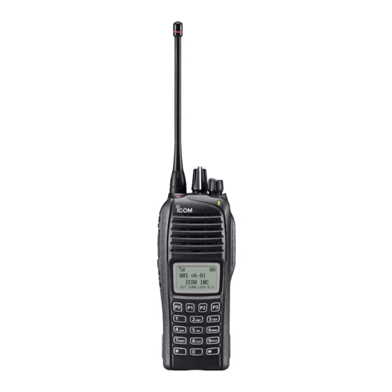
- Page 1 INSTRUCTION MANUAL VHF TRANSCEIVERS iF3260 Series UHF TRANSCEIVERS iF4260 Series This device complies with Part 15 of the FCC Rules. Operation is subject to the condition that this device does not cause harmful interference. The photo shows the UHF transceiver.
-
Page 2: Explicit Definitions
Systems, Inc. This voice coding Technology is licensed solely for use within this Communications Equipment. The user of Icom, Icom Inc. and the Icom logo are registered trademarks of Icom Incor- this Technology is explicitly prohibited from attempting to ex-... -
Page 3: Precautions
Exposing the inside of the transceiver to dust or packs with Icom radios or Icom chargers. Only Icom battery water will result in serious damage to the transceiver. packs are tested and approved for use with Icom radios or DO NOT operate the transceiver near unshielded electri- charged with Icom chargers. -
Page 4: Fcc Information
CAUTION: Changes or modifications to this transceiver, not For IC-F4261, IC-F4263 expressly approved by Icom Inc., could void your authority • The GPS receiver may not work if the transceiver transmits to operate this transceiver under FCC regulations. -
Page 5: Table Of Contents
TABLE OF CONTENTS IMPORTANT ................i Automatic Key Lock function ........18 ■ EXPLICIT DEFINITIONS ............i Priority A channel selection ........18 ■ VOICE CODING TECHNOLOGY .......... i 4 BATTERY CHARGING ..........19–23 PRECAUTIONS ..............ii Caution ...............19 ■ FCC INFORMATION ............iii Optional battery chargers ...........21 ■... -
Page 6: Accessories
ACCESSORIES Supplied accessories Accessory attachments ■ ■ Flexible antenna The following accessories are supplied. Connect the supplied flexible antenna to the antenna connector. Flexible antenna Battery pack Belt clip (This illustration is CAUTION: for the UHF type.) • NEVER carry the transceiver by holding antenna. -
Page 7: D Battery Pack
ACCESSORIES Battery pack Belt clip To attach the battery pack: To attach the belt clip: Slide the battery pack in the direction of the arrow (q) until the q Remove the battery pack if it is attached. battery release button makes a ‘click’ sound. w Slide the belt clip in the direction of the arrow until the belt clip locks and makes a ‘click’... -
Page 8: Accessories
ACCESSORIES Connector cover To attach the connector cover: To detach the connector cover: q Place the connector cover over the multi-connector. q Remove the screw using a Phillips screwdriver. w Tighten the screw. w Detach the connector cover to connect optional equip- ment. -
Page 9: Panel Description
PANEL DESCRIPTION Front panel ■ r DEALER-PROGRAMMABLE KEY [Side1] Desired functions can be preset by your dealer. (p. 6) GPS receiver* t PTT SWITCH [PTT] Hold down to transmit, release to receive. Speaker y DEALER-PROGRAMMABLE KEYS [Side2]/[Side3] Desired functions can be preset by your dealer. (p. 6) Microphone u 10-KEYPAD (Depending on the version) The keypad allows you to enter digits to:... -
Page 10: Function Display
PANEL DESCRIPTION Function display !0 MULTI-CONNECTOR ■ Connects to optional equipment. Connector cover NOTE: Attach the connec- tor cover when optional equipment is not used. See page 3 for details. CALA TXCU TXC q SIGNAL STRENGTH ICON Indicates relative signal strength level. w LOW POWER ICON Appears when low output power is selected. -
Page 11: Programmable Function Keys
Appears or blinks when a matched signal is received, de- pending on the presetting. mable function keys. Consult your Icom dealer or system operator for details con- u CALL CODE MEMORY ICON cerning your transceivers programming. Appears when the call code memory is selected. - Page 12 PANEL DESCRIPTION ZONE KEY “ZONE” SCAN ADD/DEL (TAG) KEY “SCAD” Push this key, then push [CH Up] or [CH Down] to select the ➥ Push to add a channel to, or delete it from the current scan desired zone. When [Rotary selector] selects the “operating group.
- Page 13 PANEL DESCRIPTION MEMORY CH 1/2/3/4 KEYS “CH1” “CH2” “CH3” “CH4” LONE WORKER KEY “LONE” Push to directly select memory channels 1 to 4. Push to turn the Lone Worker function ON or OFF. • If the Lone Worker function is activated, the Emergency function is automatically turned ON after the specified time period has passed MONI KEY “MON”...
- Page 14 PANEL DESCRIPTION C.TONE CH ENT KEY “TSEL” CALL KEYS “CALL” “CALA” “CALB” Push to enter the continuous tone channel selection mode. Push to transmit a 2/5-tone or BIIS ID code. Then select the desired tone frequency/code setting using • A Call transmission may be necessary before you call another sta- tion, depending on your signaling system.
- Page 15 PANEL DESCRIPTION TX CODE CHANNEL SELECT KEY “TXC” USER SET MODE KEY “SET” Push to enter the TX code channel selection mode. Then ➥ Hold down for 1 second to enter the User set mode. set the desired channel using [CH Up] or [CH Down]. •...
-
Page 16: Basic Operation
BASIC OPERATION Turning power ON ■ Battery type selection Prior to using the transceiver for the first time, the battery pack must be fully charged for optimum life and operation. When turning ON the transceiver, the battery type must be (p. -
Page 17: Channel Selection
BASIC OPERATION Channel selection ■ Voting operation (for zone selection) Several types of channel selections are available. Methods may differ, depending on the presetting. The transceiver automatically starts scanning when a zone, specified for the voting operation, is selected. NON-ZONE TYPE: The voting scan detects the signal of the repeater and auto- To select the desired operating channel: matically selects the strongest station. -
Page 18: Call Procedure
BASIC OPERATION Call procedure Receiving and transmitting ■ ■ When your system employs tone signaling, excluding CTCSS CAUTION: Transmitting without an antenna will damage and DTCS, this call procedure may be necessary prior to the transceiver. voice transmission. The tone signaling employed may be a selective calling system which allows you to call only specific Receiving: station(s) and prevents unwanted stations from contacting... -
Page 19: D Transmitting Notes
BASIC OPERATION Transmitting notes TX code channel selection • Transmit inhibit function If the transceiver has [TX Code CH Select] assigned to it, The transceiver has several inhibit functions which restrict the display can be toggled between the operating channel transmission under the following conditions: number or name, and the TX code channel number or name. -
Page 20: D Dtmf Transmission
BASIC OPERATION TX code number edit USING [TX CODE ENTER] KEY: (PMR operation only) q After pushing [TX Code CH Select], push [CH Up] or [CH If the transceiver has [TX Code CH Select] or [TX Code Down], or push [TX Code CH Up] or [TX Code CH Down] Enter] assigned, the TX code contents can be edited within to select the desired TX code channel. -
Page 21: User Set Mode
BASIC OPERATION User set mode Scrambler function ■ ■ The User set mode allows you to set seldom-changed set- The voice scrambler function provides private communica- tings and “customize” the transceiver operation to suit your tion between stations. All transceiver versions have a built-in preferences and operating style. -
Page 22: Emergency Transmission
BASIC OPERATION Emergency transmission ■ NOTES When [Emergency] is pushed for the specified time period, an emergency signal is transmitted once, or repeatedly, on the Depending on the presetting, the following functions may be specified emergency channel, depending on the presetting. automatically activated. -
Page 23: Automatic Key Lock Function
BASIC OPERATION Automatic Key Lock function ■ When [Lock] is assigned to any key, and the Automatic Key Lock timer is preprogrammed*, the key lock function can be automatically turned ON after the specified time period has passed with no key operation. While the lock function is ON, hold down [Lock] for 1 second to turn the function OFF. -
Page 24: Battery Charging
• R DANGER! Use and charge only specified Icom battery • R DANGER! DO NOT expose the battery to rain, snow, packs with Icom radios or Icom charger. Only Icom battery seawater, or any other liquids. -
Page 25: D Charging Caution
If years, even if still holds a charge. The inside battery matrial- will deteriorate after a period of time, even with little use. any of these conditions occur, contact your Icom dealer or distributor. Charging caution •... -
Page 26: Optional Battery Chargers
BATTERY CHARGING Optional battery chargers ■ Rapid charging with the BC-160 Regular charging with the BC-171 The optional BC-160 provides rapid charging of the Li-ion The optional BC-171 provides regular charging of the Li-ion battery pack. battery pack. Charging time: Approximately 3.5 hours with the BP-232WP Charging time: Approximately 11 hours with the BP-232WP The following items are additionally required: The following items are additionally required:... - Page 27 BATTERY CHARGING AD-106 installation Rapid charging with the BC-119N+AD-106 The AD-106 must be installed into the BC- The optional BC-119N provides rapidly charges the Li-ion charger adapter 119N or BC-121N before battery charging. battery pack. Charging time: Approximately 3.5 hours with the BP-232WP q Connect the AD-106 and the BC-119N/ charger adapter...
- Page 28 BATTERY CHARGING Rapid charging with the BC-121N+AD-106 The optional BC-121N allows up to 6 battery packs to be si- IMPORTANT: Battery charging caution multaneously charged. Ensure the guide tabs on the battery pack are correctly Charging time: Approximately 3.5 hours with the BP-232WP aligned with the guide rails inside the charger adapter.
-
Page 29: Battery Case
BATTERY CASE BP-240 optional battery case ■ When using the BP-240 battery case, install six AAA (LR03) Fig.1 size alkaline batteries, as illustrated to the right. BP-240 q Unhook the battery cover release hook (q), and open the cover in the direction of the arrow (w). (Fig.1) w Install six AAA (LR03) size alkaline batteries. -
Page 30: Bp-261 Optional Battery Case
BATTERY CASE BP-261 optional battery case ■ Alkaline batteries installation BP-261 Install six AA (LR6) size alkaline batteries as described below. Unhook the battery cover release hook ( q), and open the cover in the direction of the arrow (w). (Fig.1) Fig.1 Install six AA (LR6) size alkaline batteries. - Page 31 BATTERY CASE Battery case attachment Slide the battery pack in the direction of the arrow until the To release the battery case: battery release button makes a ‘click’ sound. Slide the battery case’s battery release button in the direction of the arrow (q), and then push the release button in the direction of the arrow (w).
-
Page 32: Swivel Belt Clip
SWIVEL BELT CLIP MB-93 contents r Clip the belt clip to a place on your belt. Insert the trans- ■ ceiver into the belt clip until the base clip is fully inserted into the groove. Qty. q Belt clip ................1 w Base clip ................1 To attach t Once the transceiver is locked in place, it swivels, as illus-... -
Page 33: To Detach
SWIVEL BELT CLIP To detach ■ q Turn the transceiver upside down in the direction of the CAUTION: HOLD THE TRANSCEIVER TIGHTLY WHEN HANGING arrow and pull it out of the belt clip. OR DETACHING THE TRANSCEIVER FROM THE BELT CLIP. -
Page 34: Speaker Microphone
SPEAKER MICROPHONE Optional HM-184/HM-184H To attach ■ ■ Attach the connector of the speaker microphone into the multi Microphone connector on the transceiver and tighten the screw. Speaker Belt clip PTT SWITCH Hold down to Screw transmit; release to receive. Coin Turn OFF the trans- CAUTION: Firmly attach... -
Page 35: Options
OPTIONS BATTERY PACKS CHARGERS • BP-232WP • BC-119N + AD-106 ion battery pack desktop charger charger adapter Voltage: 7.4 V, Capacity: + BC-145S 2250 mAh (min.) 2300 mAh (typ.) ac adapter • Battery life For rapid charging of battery packs. An AC adapter may be supplied with the charger, depending on the version. - Page 36 Icom transceiver. • FA-SC62V/FA-SC63V high gain antennas Icom is not responsible for the destruction or damage to an FA-SC62V: 150–160 MHz Icom transceiver in the event the Icom transceiver is used with FA-SC63V: 155–165 MHz equipment that is not manufactured or approved by Icom.
-
Page 37: Safety Training Information
This radio has been tested and complies with the FCC and IC RF ex- and IC RF exposure compliance requirements to be exceeded. The posure limits for “Occupational Use Only.” In addition, your Icom radio radio is transmitting when the TX indicator lights red. You can cause complies with the following Standards and Guidelines with regard to RF the radio to transmit by pressing the “VOX/PTT”... - Page 38 RF supérieure aux limites établies par la FCC et d'IC. Lorsque le voyant DEL rouge s’allume, cette radio est en train d’émettre. La la FCC et d'IC, pour une «utilisation grand public». En outre, votre radio Icom radio émettra si vous appuyez sur le bouton du microphone.
- Page 39 MEMO...
- Page 40 A-7016D-1EX-r Printed in Japan © 2012–2013 Icom Inc. 1-1-32 Kamiminami, Hirano-ku, Osaka 547-0003, Japan Printed on recycled paper with soy ink.
Need help?
Do you have a question about the IC-F3260 Series and is the answer not in the manual?
Questions and answers