Table of Contents
Advertisement
INSTRUCTION MANUAL
VHF TRANSCEIVER
iF310
iF320
UHF TRANSCEIVER
iF410
iF420
This device complies with Part 15 of
the FCC Rules. Operation is subject to
the condition that this device does not
cause harmful interference.
American Communication Systems
Discover the Power of Communications
http://www.ameradio.com
TO ORDER – VISIT
™
Advertisement
Table of Contents

Subscribe to Our Youtube Channel
Related Manuals for Icom IC-F420


Summary of Contents for Icom IC-F420
- Page 1 INSTRUCTION MANUAL VHF TRANSCEIVER iF310 iF320 UHF TRANSCEIVER iF410 iF420 This device complies with Part 15 of the FCC Rules. Operation is subject to the condition that this device does not cause harmful interference. American Communication Systems ™ Discover the Power of Communications http://www.ameradio.com TO ORDER –...
-
Page 2: Important
16 V DC such as a 24 V battery. This connection will ruin for the IC-F310, IC-F320, IC-F410 and IC-F420 VHF/UHF the transceiver. TRANSCEIVERS... -
Page 3: Table Of Contents
SmarTrunk II™ and conventional modes ......13 CAUTION: Changes or modifications to this transceiver, not ex- SmarTrunk II™ operation ............ 13 pressly approved by Icom Inc., could void your authority to operate 5 OPTIONS ..............16 this transceiver under FCC regulations. -
Page 4: Panel Description
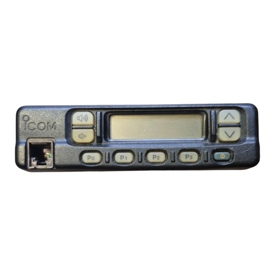
PANEL DESCRIPTION Front panel CH UP/DOWN KEYS [ (P. 3) VOLUME UP/DOWN KEYS FUNCTION DISPLAY (P. 2) (P. 2) MICROPHONE PROGRAMMABLE POWER SWITCH (P. 2) CONNECTOR FUNCTION KEYS [P0],[P1],[P2],[P3] (P. 2) (P. 3) -
Page 5: Function Display
PANEL DESCRIPTION VOLUME UP/ DOWN KEYS Function display Push to adjust the audio output level. • Minimum audio level is pre-programmed. CH UP/DOWN [ ] KEYS • Push to select the operating channel. • Can be programmed for one of several functions by your- dealer. -
Page 6: Programmable Function Keys
] programmable function keys. BANK Select a bank (a group of 16 channels). Consult your Icom Dealer or System operator for details con- • When the optional UT-105 is installed, push one or cerning your transceivers programming. more times to select a channel bank for conven- In the following explanations, programmable function names tional channels or SmarTrunk II™... - Page 7 PANEL DESCRIPTION LOCK KEY OUTPUT POWER SELECTION KEYS LOCK HIGH Electronically locks all programmable keys except Select the transmit output power temporarily or per- LOW1 the following: manently depending on the pre-setting. • [ ] (incl. CAL A and CAL B), [ ] and •...
- Page 8 PANEL DESCRIPTION TX CODE KEY ID MEMORY READ KEY TX CH ID MR Select a transmit 5-tone code (station code) channel. Recalls detected ID codes. • Push and hold to changes the contents of the sta- • Push this key, then push [ ] for selection.
-
Page 9: Operation
OPERATION Turning power ON Channel selection q Push [K ] to turn the power ON. Several types are available, and the channel selection method • A power-up alert tone sounds for may differ according to your system set up. about 1 sec. and an opening mes- Opening message may sage may appear. -
Page 10: Receiving And Transmitting
OPERATION Receiving and transmitting IMPORTANT: To maximize the readability of your signal: (1) pause briefly after pushing [ ], (2) hold the trans- ceiver 15 to 20 cm from your mouth, then speak into the RECEIVING: q Push [K microphone at a normal voice level. ] to turn the power ON. -
Page 11: D Tx Code Channel Selection
OPERATION D Tx code channel selection D DTMF transmission If the transceiver has a [ ] key, display can be toggled If the transceiver has a [ ] key, the automatic DTMF TX CH DTMF between the operating channel number (or name) and Tx transmission function is available. -
Page 12: Connection And Maintenance
CONNECTION AND MAINTENANCE Rear panel and connection Antenna Optional cable (OPC-617) red: + Supplied DC power cable black: _ Optional speaker (SP-10) -
Page 13: Unpacking
CONNECTION AND MAINTENANCE ⁄ ANTENNA CONNECTOR Supplied Accessories Connects to an antenna. Ask your Dealer about antenna selection and placement. (See p. 12) ¤ MICROPHONE HANGER Connect the supplied microphone hanger to the vehicle’s ground for on/off hook microphone functions. (See p. -
Page 14: Mounting The Transceiver
CONNECTION AND MAINTENANCE Mounting the transceiver Optional UT-96/UT-105 instal- lation The universal mounting bracket supplied with your transceiver allows overhead mounting. Please read the following instruc- The optional UT-96/UT-105 units install as follows: tions carefully. q Turn power OFF, then disconnect the DC power cable. •... -
Page 15: Optional Opc-617 Installation
CONNECTION AND MAINTENANCE Optional OPC-617 installation Antenna Install the OPC-617 as shown below. A key element in the performance of any communication sys- tem is an antenna. Ask your Dealer about antennas and the best places to mount them. Fuse replacement Two fuses are installed in the supplied DC power cable. -
Page 16: Optional Smartrunk Ii™ Operation
OPTIONAL SmarTrunk II™ OPERATION SmarTrunk II™ and SmarTrunk II™ operation conventional modes These features are enabled by a Dealer or System Operator and may not be available in your system. Contact your Dealer This transceiver is capable of SmarTrunk II™ functions. for details. - Page 17 OPTIONAL SmarTrunk II™ OPERATION D Terminating a call D Programming memory speed dial q Push and hold [M] until you hear a high-pitched beep. After completing a call, push [#] to disconnect (hang up). w Enter the memory location (0–9, A, B, C, D), the telephone IMPORTANT: If one person in the conversation terminates or subscriber number, then [1], [M] (or [3], [M] if for another a call, all participants will be cut off.
- Page 18 OPTIONAL SmarTrunk II™ OPERATION D Clear channel alerting If all channels are busy, the transceiver automatically begins searching for an open channel and beeps every ten seconds. When two short beeps (low-pitched, then high-pitched) are heard, a channel is available. Push [M], [M] immediately to re- dial the last number.
-
Page 19: Options
OPTIONS EXTERNAL SPEAKERS SP-5 UT-96 5- TONE UNIT Large speaker for good audio Provides 2-tone/5-tone signaling . quality. Input impedance: 4 Ω Max. input power: 5 W UT-105 SmarTrunk II™ Logic Board Provides SmarTrunk II™ capabili- SP-10 ties. Compact and easy-to-install. Input impedance: 4 Ω... - Page 20 A-5458D-1EX-e Printed in Japan 6-9-16 Kamihigashi, Hirano-ku, Osaka 547-0002 Japan © 1997 by Icom Inc.
Need help?
Do you have a question about the IC-F420 and is the answer not in the manual?
Questions and answers