Icom IC-F3230D series Instruction Manual
Vhf, uhf digital
Hide thumbs
Also See for IC-F3230D series:
- Instruction manual (9 pages) ,
- Instructions (2 pages) ,
- Operating manual (32 pages)
Table of Contents
Advertisement
Advertisement
Table of Contents

Related Manuals for Icom IC-F3230D series


Summary of Contents for Icom IC-F3230D series
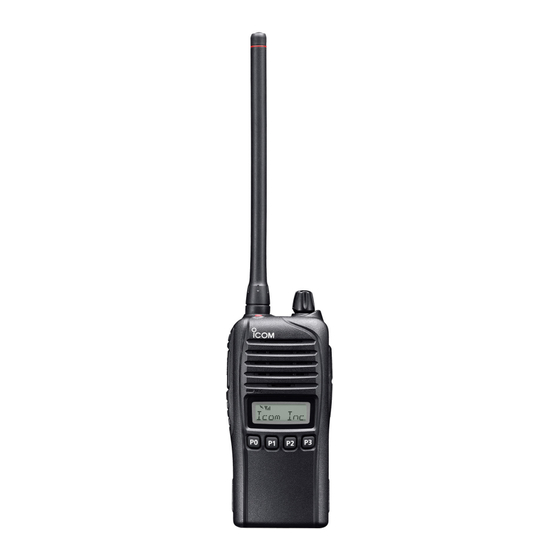
- Page 1 INSTRUCTION MANUAL VHF DIGITAL TRANSCEIVERS iF3230D Series UHF DIGITAL TRANSCEIVERS iF4230D Series This device complies with Part 15 of the FCC Rules. Opera- tion is subject to the condition that this device does not cause harmful interference. The photo shows the VHF transceiver (S type)
-
Page 2: Important
U.S. Patent Nos. #5,870,405, #5,826,222, #5,754,974, #5,701,390, #5,715,365, #5,649,050, #5,630,011, #5,581,656, #5,517,511, #5,491,772, Icom, Icom Inc. and the Icom logo are registered trademarks of Icom Incor- #5,247,579, #5,226,084 and #5,195,166. porated (Japan) in Japan, the United States, the United Kingdom, Germany,... -
Page 3: Precautions
Icom transceivers or Icom chargers. Only DO NOT push [PTT] when you do not actually intend to Icom battery packs are tested and approved for use with Icom transmit. transceivers or charged with Icom chargers. Using third-party... -
Page 4: Fcc Information
CAUTION: Changes or modifications to this transceiver, not wise, the installed battery pack or batteries will become ex- expressly approved by Icom Inc., could void your authority to hausted, and will need to be recharged or replaced. operate this transceiver under FCC regulations. -
Page 5: Table Of Contents
TABLE OF CONTENTS IMPORTANT ................i ■ BP-240 optional battery case ........17 EXPLICIT DEFINITIONS ............i ■ BP-261 optional battery case ........18 VOICE CODING TECHNOLOGY .......... i 6 SPEAKER MICROPHONE ..........20 PRECAUTIONS ..............ii ■ Optional HM-168LWP description ......20 FCC INFORMATION ............iii ■... -
Page 6: Accessories
ACCESSORIES ■ Supplied accessories D Battery pack NOTE: Some accessories are not supplied, depending on the transceiver version. To attach the battery pack: Slide the battery pack in the direction of the arrow (q) until Battery pack Battery charger* the battery release button makes a ‘click’ sound. Belt clip Power adapter* NOTE: Push on the bottom of the pack to make sure the... -
Page 7: D Jack Cover
ACCESSORIES D Belt clip D Jack cover To attach the belt clip: To attach the jack cover: q Remove the battery pack if it is attached. q Attach the jack cover to the [MIC/SP] jack. (q) w Slide the belt clip in the direction of the arrow until the belt w Tighten the screws. -
Page 8: Panel Description
PANEL DESCRIPTION ■ Front panel y DEALER-PROGRAMMABLE KEYS [P0] to [P3] D esired functions can be independently programmed by your dealer. (p. 5) u FUNCTION DISPLAY (p. 4) Displays a variety of information such as an operating channel number, channel name, User Set mode contents, Speaker and so on. -
Page 9: Function Display
PANEL DESCRIPTION ■ Function display t AUDIBLE ICON ➥ In the analog mode, appears when the CTCSS (DTCS) squelch mute is released while holding down [Monitor]. ➥ In the digital mode, appears while holding down [Moni- tor]. y ENCRYPTION ICON In the digital mode, appears when the encryption function is activated. -
Page 10: Programmable Function Keys
• When a scan is started with the Power ON Scan or Automatic scan function, push this key to cancel it. The cancelled scan re- Consult your Icom dealer or system operator for details con- sumes after a preprogrammed time period. - Page 11 PANEL DESCRIPTION PRIORITY A CHANNEL, PRIORITY B CHANNEL LOCK Push to select the Priority A or Priority B channel. ➥ Hold down this key until “LOCK ON” is displayed to elec- tronically lock all programmable keys except the following: PRIORITY A CHANNEL (REWRITE), [Moni], [Lock], [Emergency]*, [Surveillance], [Siren], [Lone PRIORITY B CHANNEL (REWRITE) Worker]*, [Light] and [Shift].
-
Page 12: Panel Description
PANEL DESCRIPTION ■ Programmable function keys (Continued) SIREN SHIFT Hold down for 1 second to sound the siren. Push to toggle the Normal mode key functions and the Shift This function can be used for situations other than an emer- mode key functions. -
Page 13: Basic Operation
BASIC OPERATION ■ Turning power ON D Battery type selection Prior to using the transceiver for the first time, the battery pack must be fully charged for optimum life and operation. The battery type must be selected according to the attached (p. -
Page 14: Channel Selection
BASIC OPERATION ■ Channel selection ■ User set mode The User Set mode allows you to set seldom-changed set- Several types of channel selections are available. Methods tings. If the transceiver has [User Set Mode] assigned to it, may differ, depending on your system set up. you can “customize”... -
Page 15: Receiving And Transmitting
BASIC OPERATION ■ Receiving and transmitting D Transmitting notes CAUTION: Transmitting without an antenna may damage the transceiver. See page 1 for accessory attachments. • Transmit inhibit function The transceiver has several inhibit functions which restrict Receiving: transmission under the following conditions: q Rotate [VOL] to turn ON the power. -
Page 16: Battery Charging
If R DANGER! NEVER use or leave battery packs in areas with any of these conditions occur, contact your Icom dealer or temperatures above +60˚C (+140˚F). High temperature build- distributor. -
Page 17: D Charging Caution
+113˚F) (+10˚C to +40˚C; +50˚F when: . Icom recommends charging the battery at +20˚C to +104˚F) • Approximately five years have passed since the battery was . The battery may heat up or rupture if charged out of the (+68˚F) -
Page 18: Battery Chargers
BATTERY CHARGING ■ Battery chargers D Rapid charging with the BC-160 D Regular charging with the BC-171 The optional BC-160 rapidly charges the Li-ion battery pack. The optional BC-171 regularly charges the Li-ion battery • A power adapter (may be supplied with BC-160, depending pack. - Page 19 BATTERY CHARGING D AD-106 installation D Rapid charging with the BC-119N+AD-106 The AD-106 must be installed into the BC- The optional BC-119N rapidly charges the Li-ion battery charger adapter 119N or BC-121N before battery charging. pack. The following items are additionally required. ➥...
- Page 20 BATTERY CHARGING D Rapid charging with the BC-121N+AD-106 D Rapid charging with the BC-197 The optional BC-121N can simultaneously charge up to 6 The optional BC-197 can simultaneously charge up to 6 Li-ion Li-ion battery packs. The following items are additionally re- battery packs.
-
Page 21: Battery Charging
BATTERY CHARGING IMPORTANT: Battery charging caution Ensure the guide tabs on the battery pack are correctly aligned with the guide rails inside the charger adapter. (This illustration is of the BC-160.) Tabs Guide rail... -
Page 22: Battery Case
BATTERY CASE ■ BP-240 optional battery case When using the BP-240 battery case, install six AAA (LR03) Fig.1 size alkaline batteries, as illustrated to the right. The BP-240 BP-240 is constructed to the IPX4 waterproof standard. q Unhook the battery cover release hook (q), and open the cover in the direction of the arrow (w). -
Page 23: Bp-261 Optional Battery Case
BATTERY CASE ■ BP-261 optional battery case D Alkaline batteries installation BP-261 Install six AA (LR6) size alkaline batteries as described below. The BP-261 is constructed to the IPX4 waterproof standard. q Unhook the battery cover release hook (q), and open the cover in the direction of the arrow (w). - Page 24 BATTERY CASE ■ BP-261 optional battery case (Continued) D Attaching D Detaching Slide the battery pack in the direction of the arrow until the Slide the battery case’s battery release button in the direction battery release button makes a ‘click’ sound. of the arrow (q), and then push the release button in the di- rection of the arrow (w).
-
Page 25: Speaker Microphone
SPEAKER MICROPHONE ■ Optional HM-168LWP description ■ Attaching Alligator type clip Attach the connector of the speaker-microphone into the [SP To attach the speaker-mic. MIC] jack on the transceiver and tighten the screws with your to your shirt or collar, etc. fingers. -
Page 26: Optional Swivel Belt Clip
OPTIONAL SWIVEL BELT CLIP ■ MB-93 contents r Clip the belt clip to a part of your belt. And insert the trans- ceiver into the belt clip until the base clip inserted fully into the groove. Qty. q Belt clip ................1 w Base clip .................1 ■... -
Page 27: Detaching
OPTIONAL SWIVEL BELT CLIP ■ Detaching w Release the battery pack if it is attached. (p. 1) q Turn the transceiver upside down in the direction of the e Pinch the clip (q), and slide the base clip in the direction arrow and pull it out of the belt clip. -
Page 28: Options
OPTIONS D BATTERY PACK • BC-160 + BC-123S desktop charger ac adapter For rapid charging of battery packs. A power adapter may Battery pack Voltage Capacity Battery life* be supplied with the charger, depending on the versions. VHF 19 hrs. 2250 mAh (min.) Charging time: Approximately 3.5 hours for the BP-232WP. - Page 29 • HM-166LA earphone microphone Icom is not responsible for the destruction or damage to an Ideal for hands-free operation: clip the HM-166LA (with inte- Icom transceiver in the event the Icom transceiver is used with grated PTT switch) to your lapel or breast pocket.
-
Page 30: Safety Training Information
This radio has been tested and complies with the FCC and IC RF FCC and IC RF exposure compliance requirements to be exceed- exposure limits for “Occupational Use Only”. In addition, your Icom ed. The radio is transmitting when the TX indicator lights red. You radio complies with the following Standards and Guidelines with re- can cause the radio to transmit by pressing the “PTT”... - Page 31 Interférence électromagnétique et compatibilité radiofréquences et des micro-ondes. En mode de transmission, votre radio Icom produit de l’énergie de RF qui • Les accessoires illustrés à la p. 23-24 sont approuvés pour une utilisa- peut provoquer des interférences avec d’autres appareils ou systèmes. Pour tion avec ce produit.
- Page 32 A-7082D-1EX-w Printed in Japan © 2013–2015 Icom Inc. 1-1-32 Kamiminami, Hirano-ku, Osaka 547-0003, Japan Printed on recycled paper with soy ink.
Need help?
Do you have a question about the IC-F3230D series and is the answer not in the manual?
Questions and answers