
Related Manuals for Icom IC-F310S


Summary of Contents for Icom IC-F310S
- Page 1 INSTRUCTION MANUAL VHF TRANSCEIVER iF310S iF320S UHF TRANSCEIVER iF410S iF420S This device complies with Part 15 of the FCC Rules. Operation is subject to the condition that this device does not cause harmful interference.
-
Page 2: Important
CAUTION If disregarded, inconvenience only. No risk NOTE of personal injury, fire or electric shock. Versions of the IC-F310S/F320S/F410S/F420S which display “CE” on the serial number seal, comply with the essential re- quirements of the 89/336/EEC directive for Electromagnetic Compatibility. -
Page 3: Table Of Contents
The transceiver will become hot when operating continuously for long periods. For U.S.A. only CAUTION: Changes or modifications to this transceiver, not ex- pressly approved by Icom Inc., could void your authority to operate this transceiver under FCC regulations. TABLE OF CONTENTS IMPORTANT ... i EXPLICIT DEFINITIONS ... -
Page 4: Panel Description
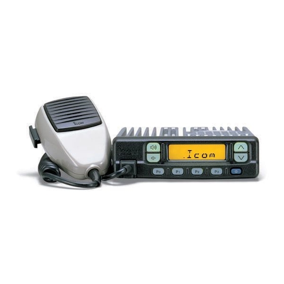
PANEL DESCRIPTION Front panel q VOLUME UP/DOWN KEYS r MICROPHONE CONNECTOR FUNCTION LED (p. 2) (p. 2) TX / RX PROGRAMMABLE FUNCTION KEYS [P0],[P1],[P2],[P3] (p. 2) w CH UP/DOWN KEYS [ e POWER SWITCH (p. 3) (p. 3) (p. 2) -
Page 5: Function Led
q VOLUME UP/ DOWN KEYS Push to adjust the audio output level. • Minimum audio level is pre-programmed. w CH UP/DOWN [ ] KEYS • Push to select the operating channel. • Can be programmed for one of several functions by your- dealer. -
Page 6: Programmable Function Keys
Programmable function keys The following functions can be assigned to the programmable function keys [P0], [P1], [P2], [P3], [ Consult your Icom dealer or system operator for details con- cerning your transceivers programming. In the following explanations, programmable function names are bracketed, the specifc switch used to activate the func- tion depends on programming. - Page 7 AUTO :Turns ON/OFF depending on the ACC socket pin 1 voltage. ON: Low (0 V) OFF: High (12 V) * Even when turned OFF, the LED lights slightly. OPERATING CHANNEL KEYS CH 1 Select an operating channel directly. CH 2 CH 3 CH 4 OUTPUT POWER SELECTION KEYS...
- Page 8 PANEL DESCRIPTION TRUNKING GROUP SWITCH Push to select the trunking group. VOICE SCRAMBLER SWITCH SCRM • Push and hold to turn the voice scrambler function ON. • Push to turn the voice scrambler function OFF. NOTE: • Optional UT-109 (#02) or UT-110 (#02) VOICE SCRAMBLER UNIT is required.
-
Page 9: Operation
Turning power ON q Push [K ] to turn the power ON. w If the transceiver is programmed for a start up passcode, input digit codes as directed by your System operator. • The keys in the diagram below can be used for password input: •... -
Page 10: Receiving And Transmitting
OPERATION Receiving and transmitting RECEIVING: q Push [K ] to turn the power ON. w Push [ ] to select a channel. e When receiving a call, adjust the volume [UP] or [DOWN] to a comfortable listening level. TRANSMITTING: r Take the microphone off hook. •... -
Page 11: D Dtmf Transmission
D DTMF transmission If the transceiver has a [ ] key, the automatic DTMF DTMF transmission function is available. DScrambler function A UT-109 (#02) or UT-110 (#02) optional voice scrambler unit provides hight performance private communication between stations with the same scrambler codes. q Push and hold [ ] to scrambler function ON. -
Page 12: Connection And Maintenance
CONNECTION AND MAINTENANCE Rear panel and connection Optional cable (OPC-617) Supplied DC power cable Optional speaker (SP-10, SP-22) Antenna red: + black: _... -
Page 13: Supplied Accessories
Mounting screws (M5 12) . 4 i Self-tapping screws (M5 20) ... 4 o Flat washers ... 4 !0 Spring washers ... 4 !1 Nuts ... 4 !2 Fuses ... 2 IC-F310S/F410S: 15 A IC-F320S/F420S: 20 A !3 Function name stickers* 1705 LCD SEAL(A) -
Page 14: Mounting The Transceiver
CONNECTION AND MAINTENANCE Mounting the transceiver The universal mounting bracket supplied with your transceiver allows overhead mounting. Please read the following instruc- tions carefully. • Mount the transceiver securely with the 4 supplied screws to a sturdy surface which can support more then 1.5 kg. Flat washer Spring washer When using... -
Page 15: Optional Opc-617 Installation
Fuse rating IC-F310S/F410S: 15 A, IC-F320S/F420S: 20 A Cleaning If the transceiver becomes dusty or dirty, wipe it clean with a y Horn drive cont. OUT dry, soft cloth. -
Page 16: Optional Smartrunk Ii™ Operation
OPTIONAL SmarTrunk II™ OPERATION SmarTrunk II™ and conventional modes This transceiver is capable of SmarTrunk II™ functions. The optional UT-105 allows communication in conventional channels or SmarTrunk II™ channels. NOTE: Connect an optional HM-100T . Contact your dealer for details. PHONE SmarTrunk II™... -
Page 17: Last Number Redial
D Terminating a call After completing a call, push [#] to disconnect (hang up). IMPORTANT: If one person in the conversation terminates a call, all participants will be cut off. D Last number redial Push [M], [M] to automatically redial the last number called. •... - Page 18 OPTIONAL SmarTrunk II™ OPERATION D Clear channel alerting If all channels are busy, the transceiver automatically begins searching for an open channel and beeps every ten seconds. When two short beeps (low-pitched, then high-pitched) are heard, a channel is available. Push [M], [M] immediately to re- dial the last number.
-
Page 19: Options
EXTERNAL SPEAKERS SP-5 Large speaker for good audio quality. Input impedance: 4 Max. input power: 5 W SP-10 Compact and easy-to-install. Input impedance: 4 Max. input power: 5 W SP-22 Compact and easy-to-install Input impedance: 4 Max. input power: 5 W MICROPHONES HM-100T DTMF microphone. - Page 20 A-5560D-1EX Printed in Japan © 6-9-16 Kamihigashi, Hirano-ku, Osaka 547-0002 Japan 1998 by Icom Inc.
Need help?
Do you have a question about the IC-F310S and is the answer not in the manual?
Questions and answers