
Related Manuals for Advantech TPC-662G-B1E


Summary of Contents for Advantech TPC-662G-B1E
- Page 1 TPC-66X Series AMD LX800 Touch Panel Computers with 6.4"/ 5.6" VGA TFT LCD User Manual...
- Page 2 No part of this man- ual may be reproduced, copied, translated or transmitted in any form or by any means without the prior written permission of Advantech Co., Ltd. Information provided in this manual is intended to be accurate and reli- able.
- Page 3 Product Warranty (2 years) Advantech warrants to you, the original purchaser, that each of its prod- ucts will be free from defects in materials and workmanship for two years from the date of purchase. This warranty does not apply to any products which have been repaired or...
- Page 4 This product has passed the CE test for environmental specifications when shielded cables are used for external wiring. We recommend the use of shielded cables. This kind of cable is available from Advantech. Please contact your local supplier for ordering information.
- Page 5 Safety Instructions Read these safety instructions carefully. Keep this User's Manual for later reference. Disconnect this equipment from any AC outlet before cleaning. Use a damp cloth. Do not use liquid or spray detergents for clean- ing. For plug-in equipment, the power outlet socket must be located near the equipment and must be easily accessible.
- Page 6 The sound pressure level at the operator's position according to IEC 704- 1:1982 is no more than 70 dB (A). DISCLAIMER: This set of instructions is given according to IEC 704-1. Advantech disclaims all responsibility for the accuracy of any statements contained herein. TPC-66X Series User Manual...
-
Page 7: Table Of Contents
Contents Chapter 1 General Information ........2 Introduction ............... 2 Specifications ..............3 1.2.1 System Kernel ..............3 1.2.2 I/O Ports ................. 3 1.2.3 Safety and Environment ..........3 LCD Specifications ............4 Touchscreen Specifications..........4 Power................. 4 I/O Ports Arrangement ............5 Figure 1.1:I/O Port Arrangement ........ - Page 8 Figure 4.13:Install Wizard - 3 ........24 Figure 4.14:Driver Installation Complete ....25 Chapter 5 Features in Windows XP Embedded... 28 EWF ................28 HORM................29 Advantech Utilities............29 5.3.1 Version Information ............. 30 5.3.2 OSLock and OSUnLock ..........30 5.3.3 HORM .................
- Page 9 Figure E.3:Install Wizard - 2 ........59 Figure E.4:Install Wizard - 3 ........59 Uninstall the Driver............60 Figure E.5:Uninstall -1 ..........60 Figure E.6:Uninstall -2 ..........60 Touchscreen Calibration ..........61 Figure E.7:Standard Calibration -1 ......61 Figure E.8:Standard Calibration -2 ......62 Figure E.9:Standard Calibration -3 ......
- Page 10 TPC-66X Series User Manual...
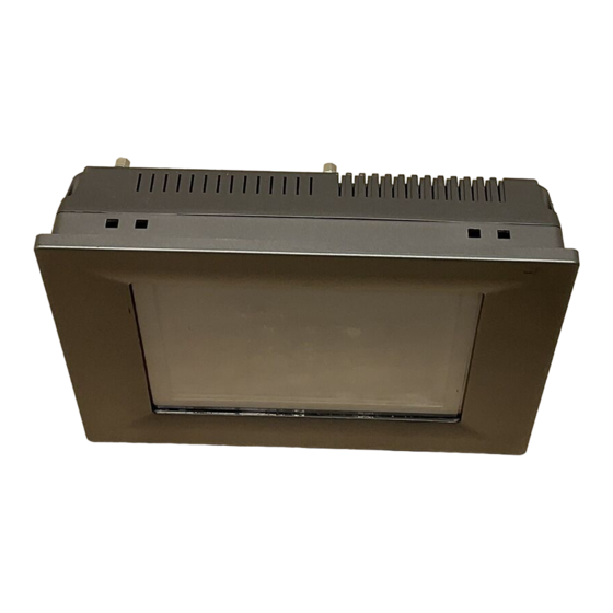
- Page 11 General Information This chapter gives background infor- mation on TPC-66X Series. Sections include: • Introduction • Specifications • I/O Ports Arrangement • Panel Mounting • Exploded Diagram • Dimensions & Cutout...
-
Page 12: Chapter 1 General Information
PC-104. This makes it easy to expand with the required PC-104 modules. • Windows CE Support In addition to the OS support of Windows XP, Advantech offers plat- form support for Windows CE and Windows XP embedded. The optional Windows CE operating system specifically for the TPC-66X Series is available for Windows CE application program builders. -
Page 13: Specifications
1.2 Specifications 1.2.1 System Kernel • CPU: GeodeLink Control Processor LX800 500MHz • BIOS: Award 512KB flash memory • South Bridge: GeodeLink Control Processor CS5536 • VGA: GeodeLink Control Processor LX800 500MHz • Ethernet: Realtek RTL8100BL; IEEE 802.3u protocol compatible •... -
Page 14: Lcd Specifications
1.3 LCD Specifications • Display Type: TFT color LCD • Size (diagonal): 6.4” • Maximum Resolution: 640 x 480 (VGA) • Maximum Colors: 256,000 • Pixel Pitch (W x H, mm): 0.203 x 0.203 • Viewing Angle: 90° • Luminance (cd/m² ): 150 •... -
Page 15: I/O Ports Arrangement
1.6 I/O Ports Arrangement The arrangement of the I/O ports is shown in Figure 1.1. Figure 1.1: I/O Port Arrangement 1.7 Panel Mounting There is an adhesive waterproof gasket on the Mg-AL front bezel. Make sure the waterproof gasket is in position before installing TPC-66X Series into the panel opening. -
Page 16: Exploded Diagram
Figure 1.2: Panel Mounting 1.8 Exploded Diagram Figure 1.3: Assembly (exploded) TPC-66X Series User Manual... -
Page 17: Dimensions And Cutout
1.9 Dimensions and Cutout • Weight: 0.8 kg • Dimensions: 195 x 148 x 44.5 mm (W x H x D) • Cutout: 188 x 141 mm (suggested) Figure 1.4: Dimensions & Cutout Chapter 1... - Page 18 TPC-66X Series User Manual...
- Page 19 System Setup This chapter provides a brief explana- tion for operating TPC-66X Series.
-
Page 20: Chapter 2 System Setup
Chapter 2 System Setup You can quickly get up and running by following the step-by-step instruc- tions below. Unpack the TPC-66X Series package. Please check the packing list at the beginning of this manual to make sure every item is there. Figure 2.1: Unpack the Package Install a CompactFlash card containing Windows CE, embedded Windows XP or another operating system. - Page 21 Connect the power connector to the 24 VDC power lines. The power lines can either be from some power adapter or an in-house power source. Figure 2.3: Power Connector and Power Lines Figure 2.4: Pin Assignment on the Power Receptor Warning The system may be damaged when the power is turned on if the power source is not con-...
- Page 22 Plug the power lines into the system power receptor. Figure 2.5: Plugging in the Power Line Turn on the System Figure 2.6: Turn on the System Calibrate the touchscreen. The detailed procedure is described in the appendix. TPC-66X Series User Manual...
- Page 23 System Engine...
-
Page 24: Chapter 3 System Engine
Chapter 3 System Engine Table 3.1: Mainboard Connectors & Jumper Settings Label Function Description LCD POWER LCD INVERTER Connector CompactFlash socket Internal IDE 44pin (2mm) connector USB1 Two USB Type-A Female to on panel. USB2 Two USB Type-A Female to on panel. ETHERNET RJ45 LAN PORT Standard Mini-DIN 6-pin support K/B and Mouse... - Page 25 Figure 3.1: Main Board Connectors - 1 Figure 3.2: Main Board Connectors - 2 Chapter 3...
- Page 26 TPC-66X Series User Manual...
- Page 27 Software Configuration Sections include: • VGA Driver Installation • Advantech COM Installation • Entertainment Encryption/ Decryption Driver Installation...
-
Page 28: Chapter 4 Software Configuration
There are related utilities and drivers of TPC-66X Series for Windows XP. Please insert the support CD-ROM into your CD-ROM driver and install the VGA graphics driver, Advantech com driver, Touch- screen driver and WDM driver sequentially. Touchscreen installation is described in the appendix. - Page 29 Figure 4.2: Update Driver Step 3: Then follow the update wizard processures. Figure 4.3: Update Wizard-1 Chapter 4...
- Page 30 Figure 4.4: Update Wizard-2 Figure 4.5: Update Wizard-3 TPC-66X Series User Manual...
- Page 31 Figure 4.6: Update Wizard-4 Figure 4.7: Update Wizard-5 Chapter 4...
- Page 32 Figure 4.8: Update Wizard-6 Step 4: After you successfully update the driver, you can see the VGA successfully installed from the device manager. Figure 4.9: Driver Installation Complete TPC-66X Series User Manual...
-
Page 33: Entertainment Encryption/Decryption Driver
4.2 Entertainment Encryption/Decryption Driver Step 1: Insert the CD-ROM and go to “Device Manager”. Click “Enter- tainment Encryption/ Decryption Controller” Figure 4.10: Device Manager Step 2: Following the install shield wizard to finish the setup. Figure 4.11: Install Wizard - 1 Chapter 4... - Page 34 Figure 4.12: Install Wizard - 2 Figure 4.13: Install Wizard - 3 TPC-66X Series User Manual...
- Page 35 Step 4: The driver is successfully installed. You can check via “Device Manager” as the below. Figure 4.14: Driver Installation Complete Chapter 4...
- Page 36 TPC-66X Series User Manual...
- Page 37 Features in Windows XP Embedded Sections include: • EWF • HORM • Advantech Utilities...
-
Page 38: Chapter 5 Features In Windows Xp Embedded
This mode is manually enabled by customers after they finish all their changes on system such as installing their applications or adjusting system setting. Advantech provides a pair of utilities to operate EWF, OSLock and OSUnLock. The setting is stated in the section later. TPC-66X Series User Manual... -
Page 39: Horm
Run OSLock, and then system reboot automatically. Open those software that customers want to directly use after system resume from hibernation. Hibernate via Advantech HORM utility: Please Click Start Menu->All Programs->Advantech->HORM HORM environment remains all along unless the following events occur: Run EWF commit command (ewfmgr c: -commit) and then reboot sys- tem. -
Page 40: Version Information
5.3.2 OSLock and OSUnLock The two utilities assist users to enable or disable EWF. Please go to Start Menu-> All Programs-> Advantech. The default setting of EWF is dis- abled. Users can protect C partition from any disk writing via OSLock that is to enable EWF RAM REG Mode. - Page 41 Serial Port Settings...
-
Page 42: Appendix A Serial Port Settings
Appendix A Serial Port Settings There are two serial ports, COM1 and COM2, on TPC-66X Series. The serial port, COM1, supports standard RS-232 and the serial port COM2 on the TPC-66X Series is adjustable. It can be set to RS-232, RS-422 or RS-485. -
Page 43: Data Format Control Setting (Sw2)
RS-232 RS-422 RS-485 NDCD NDTR NDSR NRTS NCTS A.2 Data Format Control Setting (SW2) Function Data Format RS422 9 bits *10 bits RS485 RTS Control 11 bits 12 bits Auto Flow x = On o = Off *= Default Control Appendix A... -
Page 44: Baud Rate Setting (Sw3)
A.3 Baud Rate Setting (SW3) Baud Rate 1200 bps 2400 bps 4800 bps * 9600 bps 19.2 Kbps 38.4 Kbps 57.6 Kbps 115.2 Kbps = On 0 = Off *= Default TPC-66X Series User Manual... - Page 45 Watchdog Timer Programming...
-
Page 46: Appendix B Watchdog Timer Programming
Appendix B Watchdog Timer Program- ming B.1 Overview The TPC-66X Series watchdog timer can be used to monitor system soft- ware operation and take corrective action if the software fails to function after the programmed period. This section describes the operation of the watchdog timer, and how to program it. -
Page 47: Watchdog Timer Programming
B.2 Watchdog Timer Programming The I/O port address of the watchdog timer is 2E(hex) and 2F(hex), 2E (hex) is the address port. 2F(hex) is the data port. You must first assign the address of register by writing address value into address port 2E(hex), then write/read data to/from the assigned register through data port 2F (hex). - Page 48 Table B.1: Watchdog Timer Registers Address of Attribute Description register (2E) Read/Write Value (2F) description 87 (hex) ----- Write this address to I/O address port 2E (hex) twice to unlock the W83627HF 07 (hex) write Write 08 (hex) to select register of watchdog timer.
-
Page 49: Example Programs
B.3 Example Programs 1. Enable watchdog timer and set 10 sec. as timeout interval ;----------------------------------------------------------- Mov dx,2eh ; Unlock W83627HF Mov al,87h Out dx,al Out dx,al ;----------------------------------------------------------- Mov al,07h ; Select registers of watchdog timer Out dx,al Inc dx Mov al,08h Out dx,al ;----------------------------------------------------------- Dec dx ;... - Page 50 Out dx,al Inc dx Mov al,10 Out dx,al ;----------------------------------------------------------- Dec dx ; lock W83627HF Mov al,0aah Out dx,al 2. Enable watchdog timer and set 5 minutes as timeout interval ;----------------------------------------------------------- Mov dx,2eh ; unlock W83627H Mov al,87h Out dx,al Out dx,al ;----------------------------------------------------------- Mov al,07h ;...
- Page 51 Out dx,al Inc dx In al,dx Or al,08h Out dx,al ;----------------------------------------------------------- Dec dx ; Set timeout interval as 5 minutes and start counting Mov al,0f6h Out dx,al Inc dx Mov al,5 Out dx,al ;----------------------------------------------------------- Dec dx ; lock W83627HF Mov al,0aah Out dx,al 3.
- Page 52 Mov al,30h Out dx,al Inc dx Mov al,01h Out dx,al ;----------------------------------------------------------- Dec dx ; Enable watchdog timer to be reset by mouse Mov al,0f7h Out dx,al Inc dx In al,dx Or al,80h Out dx,al ;----------------------------------------------------------- Dec dx ; lock W83627HF Mov al,0aah Out dx,al 4.
- Page 53 Dec dx ; Enable the function of watchdog timer Mov al,30h Out dx,al Inc dx Mov al,01h Out dx,al ;----------------------------------------------------------- Dec dx ; Enable watchdog timer to be strobed reset by keyboard Mov al,0f7h Out dx,al Inc dx In al,dx Or al,40h Out dx,al ;-----------------------------------------------------------...
- Page 54 ;----------------------------------------------------------- Dec dx ; Enable the function of watchdog timer Mov al,30h Out dx,al Inc dx Mov al,01h Out dx,al ;----------------------------------------------------------- Dec dx ; Generate a time-out signal Mov al,0f7h Out dx,al ;Write 1 to bit 5 of F7 register Inc dx In al,dx Or al,20h...
- Page 55 Watchdog Timer Programming on WinCE...
-
Page 56: Appendix C Watchdog Timer Programming On Wince
Appendix C Watchdog Timer Program- ming on WinCE There is a built-in watchdog timer in Windows CE 4.2 for TPC-66X Series. You can access it through the WIN32 API. TPC-66X Series pro- vides a WDT driver to allow users to enable/disable the watchdog timer. The driver name is “WDT1:”. -
Page 57: Parameters
C.1.1 Parameters • hDevice [in] Handle to the device that is to perform the operation. Call the Cre- ateFile function to obtain a device handle. • dwIoControlCode [in] Specifies the control code for the operation. This value identifies the specific operation to be performed and the type of device on which the operation is to be performed. -
Page 58: How To Use The Control Code
C.2 How to Use the Control Code There are 6 control codes for the operation codes in the WDT driver. C.2.1 IOCTL _WDT_ENABLE: Enables the watchdog timer of your application. By default, if the watch- dog timer is enabled, the WDT driver will automatically trigger itself after the specified period and your application does not need to trigger the watchdog timer. -
Page 59: Ioctl_Wdt_Gettimeout
C.2.4 IOCTL_WDT_GETTIMEOUT: Gets the Watchdog time setting. lpInBuffer: unused. nInBufferSize: unused. lpOutBuffer: The DWORD points to your watchdog time setting. The Watchdog time setting is just a number. 0 means 2 seconds, 1 means 5 seconds, 2 means 10 seconds, 3 means 15 seconds, 4 means 30 seconds, 5 means 45 seconds and 6 means 60 seconds. -
Page 60: Examples
C.3 Examples #define WDT_CODE(ID) CTL_CODE(FILE_DEVICE_UNKNOWN,ID, METHOD_BUFFERED, FILE_ANY_ACCESS) #define IOCTL_WDT_ENABLE WDT_CODE (0x900) #define IOCTL_WDT_DISABLE WDT_CODE(0x901) #define IOCTL_WDT_STROBE WDT_CODE(0x902) #define IOCTL_WDT_GET_TIMEOUT WDT_CODE(0x903) #define IOCTL_WDT_SET_TIMEOUT WDT_CODE(0x904) #define IOCTL_WDT_REBOOT WDT_CODE(0x905) // for compatibility reasons, you can define IOCTL as below: // #define IOCTL_WDT_ENABLE 0x1001 // #define IOCTL_WDT_DISABLE 0x1002 // #define IOCTL_WDT_STROBE 0x1003 // #define IOCTL_WDT_GETTIMEOUT 0x1004... - Page 61 // Set the Watchdog Timer as 10 seconds. Number 2 means 10 seconds. DeviceIoControl(m_hWDT, IOCTL_WDT_SET_TIMEOUT, &nIndex, sizeof(nIndex), NULL, 0, &dwTemp, NULL); // Enable the Watchdog timer DeviceIoControl(m_hWDT, IOCTL_WDT_ENABLE, NULL, 0, NULL, 0, &dwTemp, NULL); While (1) { // do your job here. Sleep(8000);...
- Page 62 TPC-66X Series User Manual...
- Page 63 Accessory Kit Assembly Procedure This appendix shows how to connect to a CD-ROM via the CompactFlash slot.:...
-
Page 64: Appendix D Accessory Kit Assembly Procedure
Appendix D Accessory Kit Assembly Procedure D.1 CompactFlash to IDE Transfer Kit Please follow this assembly procedure to use the CompactFlash slot to connect with a CD-ROM drive. Connect the IDE cable to the adapter board. Figure D.1: Adapter Board and IDE Cable Figure D.2: Connecting the Adapter Board TPC-66X Series User Manual... - Page 65 Note Pin 1 is marked red Insert the adapter board into the CompactFlash slot. Figure D.3: CompactFlash Slot Figure D.4: Insert the Adapter Board into the CF slot Figure D.5: Inserted Adapter Board Appendix D...
- Page 66 Connect the CD-ROM to the adapter board via the IDE cable and then connect the external power line to the CD-ROM. Figure D.6: Connect the CD-ROM via the IDE Cable Figure D.7: Plugging in the CD-ROM Drive TPC-66X Series User Manual...
- Page 67 Touchscreen Installation & Configuration This appendix demonstrates how to install the touchscreen and set the con- figuration on TPC-66X Series. This section uses Windows XP as an exam- ple.
-
Page 68: Appendix E Touchscreen Installation & Configuration
Appendix E Touchscreen Installation & Configuration E.1 Driver Installation Please insert the x86 TPC series support CD and go to the driver folder: (TPC-66X Series\Driver\DMC9000 Windows 2000-XP Driver V5.0N.1006). Click setup.exe Figure E.1: Setup.exe The screen displays the installation wizard for the PenMount software. Click “Next”. - Page 69 Figure E.3: Install Wizard - 2 Figure E.4: Install Wizard - 3 Appendix E...
- Page 70 E.2 Uninstall the Driver Please go to Settings and then select Control Panel. Please click Add/ Remove Programs. Figure E.5: Uninstall -1 Select PenMount DMC9000 and DMC9100. Click Remove button. Then, select “Yes” to remove the PenMount driver and reboot the system Figure E.6: Uninstall -2 TPC-66X Series User Manual...
- Page 71 E.3 Touchscreen Calibration The “PM”, the icon of the PenMount Control Panel, is in the menu bar after the touchscreen installation. Please click the icon “PM” to call Pen- Mount Control Panel. It contains six functions: Calibrate, Draw, Option, and About. About shows the driver version. Calibrate Two ways to calibrate the touchscreen include “Standard Calibration”...
- Page 72 Figure E.8: Standard Calibration -2 Figure E.9: Standard Calibration -3 TPC-66X Series User Manual...
- Page 73 Note Touch the red squares in sequence. The cali- bration is completed after the fifth touch red point is calibrated. Press “ESC” to skip. Advanced Calibration is for the aged touchscreens by using 4, 9, 16 or 25 points to calibrate touch panel. Figure E.10: Advanced Calibration -1 Appendix E...
- Page 74 Figure E.11: Advanced Calibration -2 Figure E.12: Plot Calibration Data TPC-66X Series User Manual...
- Page 75 Note Plot Calibration Data enabled provides the blue lines to show linearity before calibration and black lines to show linearity after calibration when you finished the advanced calibration. Draw This is to test the touchscreen operation. Its display shows touch loca- tion.
- Page 76 Figure E.14: Clear Screen Option This option is to set the operation mode and beep sounds if enabled. The operation mode, stream mode and point mode, is to enable/ disable the mouse’s ability to drag on-screen icons. Stream mode lets the mouse function as normal and dragging onscreen.
- Page 77 Fuse Specifications...
- Page 78 Appendix F Fuse Specifications F.1 Fuse Specifications Rating: 250 V AC, 3.15 A Size: 5 x 20 mm Note For your protection, the fuse is set to break if the input voltage exceeds 33 V DC. F.2 Fuse Replacement Step 1: Remove the fuse cover Step 2: Replace the damaged fuse with a new one Step 3: Place the fuse cover back into position.
Need help?
Do you have a question about the TPC-662G-B1E and is the answer not in the manual?
Questions and answers