
Related Manuals for Clarke WOODWORKER CMS10S


Summary of Contents for Clarke WOODWORKER CMS10S
- Page 1 COMPOUND SLIDING MITRE SAW COMPOUND SLIDING MITRE SAW Model Nos: CMS10S and CMS12S Part Numbers: 6501310 & 6501315 Operating & Maintenance Instructions © 0607...
-
Page 2: Specifications
200mm Please note that the details and specifications contained herein, are correct at the time of going to print. However, CLARKE International reserve the right to change specifications at any time without prior notice. Always consult the machine’s data plate DO NOT dispose of theis product with general household waste. -
Page 3: Table Of Contents
GUARANTEE This CLARKE product is guaranteed against faulty manufacture for a period of 12 months from the date of purchase. Please keep your receipt as proof of purchase. This guarantee is invalid if the product is found to have been abused or tampered with in any way, or not used for the purpose for which it was intended. -
Page 4: Safety Precautions
SAFETY PRECAUTIONS GENERAL SAFETY RULES FOR OPERATING MACHINERY WARNING: As with all machinery, there are certain hazards involved with their operation and use. Exercising respect and caution will considerably lessen the risk of personal injury. However, if normal safety precautions are overlooked or ignored, personal injury to the operator or damage to property, may result. - Page 5 11. REMOVE ADJUSTING KEYS AND WRENCHES. Form the habit of checking to see that keys and adjusting wrenches are removed from the machine before switching on. 12. DRUGS, ALCOHOL, MEDICATION. Do not operate machine while under the influence of drugs, alcohol or any medication. 13.
-
Page 6: Additional Precautions For Mitre Saws
DO NOT operate the machine with the guards removed. They must all be in place and securely fastened when performing any operation. 10. Use ONLY approved replacement saw blades. Contact your local CLARKE dealer for advice. The use of inferior blades may increase the risk of injury. -
Page 7: Electrical Connections
ELECTRICAL CONNECTIONS Connect the mains lead to a standard, 230 Volt (50Hz) electrical supply through an approved 13 amp BS 1363 plug, or a suitably fused isolator switch. WARNING! THIS APPLIANCE IS DOUBLE INSULATED IMPORTANT: The wires in the mains lead are coloured in accordance with the following code: Blue Neutral... -
Page 8: Principle Parts
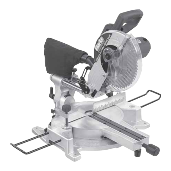
PRINCIPAL PARTS OF THE SAW Fig.1 Fig.2... -
Page 9: Features
FEATURES • As its’ name implies, the machine is a Compound Mitre Saw, capable of straight cross cutting, and cutting bevels and mitres, or a combination of the two. • The main arm, or Cutting Head, carries the motor and the tungsten carbide saw blade. -
Page 10: Cross Cutting
1 x work clamp with support bar. 2 x work supports. Any deficiency or damage should be reported to your CLARKE dealer immediately. Mount the machine on a firm solid base that will not move under load. Ensure there is an appropriate electrical supply, and adequate lighting, so that you will not be working in your own shadow. -
Page 11: Mitre Cutting
When satisfied, make a final check to ensure that all safety precautions are being observed and the ‘Groove Plate’ is correctly set - see page 13, then pull and hold the trigger and allow the blade to reach full speed. If any unusual sounds or vibrations occur, release the starter switch immediately and investigate the cause. -
Page 12: Bevel Cutting
C. Straight Bevel Cutting As with Mitre Cutting, this is a cross cutting operation, except that the blade is not perpendicular to the table, (see fig. 5). Ensure the table is set to 0 , and is Fig.5 locked in place using the table knob. -
Page 13: Cutting A Groove
E. Cutting a Groove A unique feature of this saw is its ability to produce grooves, both straight and angled. A special plate, indicated in Fig. 8a and an adjuster are used, as follows: Fig. 8 Firstly, determine the depth of your groove, and subtract this value from the thickness of your workpiece. -
Page 14: Maintenance
Should the motor not function normally, it is possible that it has become clogged with saw dust, in which case, it will be necessary to disassemble the motor in order to clean the various components. Contact your CLARKE dealer for advice. 2. Changing the Saw Blade IMPORTANT: Exercise extreme care when handling the saw blade. -
Page 15: Adjustments
Additionally, the blade MUST be rated with a maximum speed greater than 4850RPM Please note that spare blades are available from Clarke International. Please see your Clarke dealer. Replace the outer flange and screw in the centre bolt, remembering it has a left hand thread - i.e. -
Page 16: Parts Lists And Diagrams
PARTS LISTS DIAGRAMS PARTS & SERVICING For Parts & Servicing, please contact your nearest dealer, or CLARKE International, on one of the following numbers. PARTS & SERVICE TEL: 020 8988 7400 PARTS & SERVICE FAX: 020 8558 3622 e-mail as follows: PARTS: parts@clarkeinternational.com... - Page 17 PARTS DIAGRAM - CMS10S...
- Page 18 PARTS LIST - CMS10S Description Part No. Description Part No. Work Support ACCMS10S001 41 Lock Pin ACCMS10S041 Butterfly Screw ACCMS10S002 42 Main Bracket ACCMS10S042 Rubber Foot ACCMS10S003 43 Hex Hd Screw ACCMS10S043 Base ACCMS10S004 44 Depth Adjuster ACCMS10S044 Hex Hd Screw...
- Page 19 PARTS LIST - CMS10S cont. Description Part No. Description Part No. 75 Ring ACCMS10S075 108 Dust Chute ACCMS10S108 76 Bearing ACCMS10S076 109 Dust Bag ACCMS10S109 77 Upper Blade Guard ACCMS10S077 110 Pan Hd Screw ACCMS10S110 78 Screw ACCMS10S078 111 Lock Washer...
- Page 20 PARTS DIAGRAM - CMS12S...
- Page 21 PARTS LIST - CMS12S Description Part No. Description Part No. Shaft ACCMS12S050 Work Support ACCMS12S001 Butterfly Screw ACCMS12S002 Spring ACCMS12S051 Rubber Foot ACCMS12S003 Back Fence ACCMS12S052 Base ACCMS12S004 Lock Washer ACCMS12S053 Hex Hd Screw ACCMS12S005 Hex Hd Screw ACCMS12S054 Table Bearing Plate ACCMS12S006 Butterfly Screw ACCMS12S055...
- Page 22 PARTS LIST - CMS12S cont. Description Part No. Description Part No. ACCMS12S086 121 Link ACCMS12S121 Bearing ACCMS12S087 122 Flat Washer ACCMS12S122 Compression Spring ACCMS12S088 123 Lock Washer ACCMS12S123 Locking Lever ACCMS12S089 124 Pan Hd Screw ACCMS12S124 Jacket ACCMS12S090 125 Brush Holder Cover ACCMS12S125 Armature ACCMS12S091...
Need help?
Do you have a question about the WOODWORKER CMS10S and is the answer not in the manual?
Questions and answers