
Subscribe to Our Youtube Channel
Related Manuals for Clarke CMS10S2


Summary of Contents for Clarke CMS10S2
- Page 1 10”SLIDING MITRE SAW MODEL NO: CMS10S2 PART NO: 6461514 OPERATION & MAINTENANCE INSTRUCTIONS LS0312...
-
Page 2: Introduction
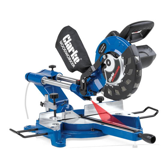
INTRODUCTION Thank you for purchasing this CLARKE 10”Sliding Mitre Saw. Before attempting to use this product, please read this manual thoroughly and follow the instructions carefully. In doing so you will ensure the safety of yourself and that of others around you, and you can look forward to your purchase giving you long and satisfactory service. -
Page 3: Table Of Contents
TABLE OF CONTENTS INTRODUCTION ................2 IMPORTANT ................2 GUARANTEE ................2 TABLE OF CONTENTS ..............3 GENERAL SAFETY RULES .............4 ADDITIONAL SAFETY RULES FOR MITRE SAWS ......5 SAFETY SYMBOLS ...............7 ELECTRICAL CONNECTIONS .............8 OVERVIEW ..................9 BEFORE USE ................10 Bench mounting ................10 Locking / Releasing the saw head ..........11 Fitting the work clamp .............. -
Page 4: General Safety Rules
GENERAL SAFETY RULES 5. If operating the power tool in a WORK AREA damp location is unavoidable, 1. Keep the work area clean and use a residual current device well lit. Cluttered and dark areas (RCD) protected supply. invite accidents. PERSONAL SAFETY 2. -
Page 5: Additional Safety Rules For Mitre Saws
GENERAL SAFETY RULES and any other condition that may 6. Dress properly. Do not wear loose affect the power tools operation. clothing or jewellery. Keep your If damaged, have the power tool hair, clothing and gloves away repaired before use. Many from moving parts. -
Page 6: Additional Safety Rules For Mitre Saws
11. Do not use any abrasive discs. your local Clarke dealer. 12. Raise the blade from the kerf in the workpiece prior to releasing the switch. 13. Ensure that the arm is securely fixed when performing bevel cuts. -
Page 7: Safety Symbols
SAFETY SYMBOLS Wear eye protection Wear ear defenders Do not put your hand near the blade Read instruction manual before use Laser Radiation, Class 2 Laser: Do not stare into the beam. Parts & Service: 020 8988 7400 / E-mail: Parts@clarkeinternational.com or Service@clarkeinternational.com... -
Page 8: Electrical Connections
ELECTRICAL CONNECTIONS WARNING! Read these electrical safety instructions thoroughly before connecting the product to the mains supply. Before switching the product on, make sure that the voltage of your electricity supply is the same as that indicated on the rating plate. This product is designed to operate on 230VAC 50Hz. -
Page 9: Overview
OVERVIEW Parts & Service: 020 8988 7400 / E-mail: Parts@clarkeinternational.com or Service@clarkeinternational.com... -
Page 10: Before Use
MITRE SAW STAND ( NOT SUPPLIED You can also mount the machine to a purpose built mitre saw stand available from your local Clarke dealer. Parts & Service: 020 8988 7400 / E-mail: Parts@clarkeinternational.com or Service@clarkeinternational.com... -
Page 11: Locking / Releasing The Saw Head
LOCKING / RELEASING THE SAW HEAD 1. Press down slightly on the operating handle and pull out the Head Lock Pin, and rotate it 90 degrees as shown. 2. Gently release the downward pressure on the operating handle and allow the head to rise to its full height. -
Page 12: Fitting Work Supports
FITTING WORK SUPPORTS 1. Loosen the work support securing screw. 2. Slide the work supports into place as shown. 3. Secure them in place by tightening the work support securing screw. DUST EXTRACTION This machine is provided with a dust extraction point for connection to a dust bag (supplied). -
Page 13: Instructions For Use
INSTRUCTIONS FOR USE Always observe the safety instructions and applicable regulations. BODY AND HAND POSITION Proper positioning of your body and hands when operating the mitre saw will make cutting easier and safer. • Never place your hands near the cutting area or blade. •... -
Page 14: Basic Saw Cuts
BASIC SAW CUTS VERTICAL STRAIGHT CROSS CUT 1. Release the table mitre lock and move the arm to the 0° position and re-tighten the table mitre lock. 2. Release the slide rail lock, and push the saw head back to the rear position. -
Page 15: Performing A Sliding Cut
PERFORMING A SLIDING CUT The guide rail allows cutting larger workpieces up to 340 mm x 78 mm using an out-down-back sliding motion. 1. Release the slide rail lock. 2. Pull the saw head towards you (1) and switch the saw on as mentioned on the previous page. -
Page 16: Bevel Cuts
BEVEL CUTS Bevel angles can be set from 45° left to vertical and can be cut with the mitre arm set between zero and a maximum of 45° mitre position right or left. 1. Loosen the bevel adjustment handle and set the bevel at the desired angle. -
Page 17: Groove Cutting
GROOVE CUTTING Your saw is equipped with a grooving stop and thumbscrew to allow for groove cutting. 1. Firstly, determine the depth of your groove, and subtract this value from the thickness of your workpiece. This will give you the height above the table surface at which the saw blade must be set. -
Page 18: Transporting
TRANSPORTING 1. Lower the head and lock it down using the head lock pin. 2. Slide the head towards you and secure in place using the slide rail lock. 3. Lock the mitre arm with the table mitre lock. 4. Lock the bevel adjustment handle with the saw head in the vertical position to make the tool as compact as possible. -
Page 19: Adjustments
ADJUSTMENTS WARNING: MAKE SURE THAT THE SAW IS SWITCHED OFF AND UNPLUGGED FROM THE MAINS SUPPLY BEFORE PERFORMING ANY ADJUSTMENTS. CHECKING AND ADJUSTING THE MITRE SETTINGS 1. Release the blade guard release lever to release the mitre arm. 2. Lower the head until the blade just enters the kerf plate. -
Page 20: Checking And Adjusting The Bevel Settings
CHECKING AND ADJUSTING THE BEVEL SETTINGS 1. Loosen the bevel clamp handle. 2. Press the saw head to the right to ensure it is fully vertical and tighten the bevel clamp handle. 3. Pull down the head until the blade just enters the kerf plate. 90 DEGREE STOP ADJUSTMENT 4. - Page 21 45 DEGREE STOP ADJUSTMENT 1. Loosen the bevel clamp handle and set the saw head as far to the left as possible (this should be the 45° angle) 2. Place a 45° set square on the table and up against the blade. NOTE: Do not touch the tips of the blade teeth with the square.
-
Page 22: Maintenance
• Additionally, the blade MUST be rated with a maximum speed of at least 6000 rpm. • Please note that spare blades are available from Clarke International. Please see your Clarke dealer. 5. Replace the outer flange and screw in the centre screw, remembering the has a LEFT HAND THREAD - i.e. -
Page 23: Changing The Carbon Brushes
CHANGING THE CARBON BRUSHES WARNING: MAKE SURE THAT THE SAW IS SWITCHED OFF AND UNPLUGGED FROM THE MAINS SUPPLY BEFORE CHANGING THE CARBON BRUSHES. A spare pair of carbon brushes are supplied with the machine. Should it become necessary to change these: 1. -
Page 24: Specifications
987 x 725 x 531 mm Weight 17 kg To obtain the stated cutting capacities, always use 254 mm saw blades with a 30 mm bore, available from your local Clarke dealer. Parts & Service: 020 8988 7400 / E-mail: Parts@clarkeinternational.com or Service@clarkeinternational.com... -
Page 25: Exploded Diagram
EXPLODED DIAGRAM Parts & Service: 020 8988 7400 / E-mail: Parts@clarkeinternational.com or Service@clarkeinternational.com... -
Page 26: Parts List
PARTS LIST Description Part No Description Part No Spring WSCMS10S2101 Main Frame WSCMS10S202 Washer WSCMS10S2103 Rubber Foot WSCMS10S203 Cover WSCMS10S2107 Workpiece Support WSCMS10S207 Guard Locking Lever WSCMS10S2109 Handle WSCMS10S210 Spring WSCMS10S2111 Pointer WSCMS10S214 Bearing WSCMS10S2116 Table WSCMS10S215 Anchor WSCMS10S2122 Table Insert + Kerf WSCMS10S221 Plate Stator... -
Page 27: Declaration Of Conformity
DECLARATION OF CONFORMITY Parts & Service: 020 8988 7400 / E-mail: Parts@clarkeinternational.com or Service@clarkeinternational.com...
Need help?
Do you have a question about the CMS10S2 and is the answer not in the manual?
Questions and answers