
Related Manuals for Clarke CMS255S


Summary of Contents for Clarke CMS255S
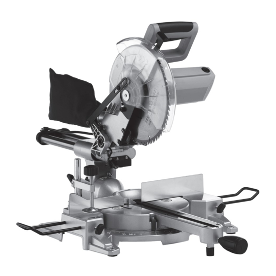
- Page 1 255MM (10”) MITRE SAW MODEL NO: CMS255S PART NO: 6461518 OPERATION & MAINTENANCE INSTRUCTIONS ORIGINAL INSTRUCTIONS LS0817-ISS 2...
- Page 2 INTRODUCTION Thank you for selecting this Clarke 255mm (10”) mitre saw. The mitre saw is used to make a quick, accurate crosscut in a workpiece at a selected angle, it must not be used for any other purposes. Read this manual before use. The warnings and cautions in this manual help you operate the mitre saw safely.
-
Page 3: Work Area
CABLE SAFETY RULES 5. If operating the power tool in a WORK AREA damp location is unavoidable, 1. Keep the work area clean and use a residual current device well lit. Cluttered and dark areas (RCD) protected supply. invite accidents. PERSONAL SAFETY 2. -
Page 4: General Safety Rules
GENERAL SAFETY RULES and any other condition that can 6. Dress properly. Do not wear loose affect the power tools operation. clothing or jewellery. Keep your If damaged, have the power tool hair, clothing and gloves away repaired before use. Many from moving parts. - Page 5 11. Do not use any abrasive discs. mitre saw stand available from your local Clarke dealer. 12. Raise the blade from the kerf in the workpiece prior to releasing the switch. 13. Make sure that the arm is securely fixed when performing bevel cuts.
-
Page 6: Safety Symbols
SAFETY SYMBOLS Wear eye protection Wear dust mask Wear ear defenders Do not put your hand near the blade Read instruction manual before use Laser Radiation, Class 2 Laser: Do not stare into the beam. Parts & Service: 020 8988 7400 / E-mail: Parts@clarkeinternational.com or Service@clarkeinternational.com... -
Page 7: Electrical Connections
ELECTRICAL CONNECTIONS WARNING: READ THESE ELECTRICAL SAFETY INSTRUCTIONS FULLY BEFORE CONNECTING THE MITRE SAW TO THE MAINS SUPPLY. This mitre saw is provided with a standard 13 amp, 230 volt (50Hz), BS 1363 plug, for connection to a standard, domestic electrical supply. Should the plug need changing at any time, make sure that a plug of identical specification is used. - Page 8 OVERVIEW Parts & Service: 020 8988 7400 / E-mail: Parts@clarkeinternational.com or Service@clarkeinternational.com...
-
Page 9: Before Use
BEFORE USE IN THE BOX 255 mm Sliding Mitre Saw with Laser 60 tooth TCT Blade Work Clamp Dust Bag 2 x Work Supports 6 mm Hex key Speak to your supplier if a part is missing. ATTACH TO A WORKBENCH There are mounting holes in the feet for bolting to a workbench. - Page 10 (Inner 35mm / Outer 45 mm). USE A MITRE SAW STAND ( NOT SUPPLIED You can also attach the mitre saw to a mitre saw stand available from your local Clarke supplier. Parts & Service: 020 8988 7400 / E-mail: Parts@clarkeinternational.com or Service@clarkeinternational.com...
-
Page 11: Body And Hand Position
INSTRUCTIONS FOR USE Always obey the safety instructions and applicable regulations. BODY AND HAND POSITION Correct positioning of your body and hands when you operate the mitre saw will make cutting easier and safer. • Do not put your hands near the cutting area or blade. •... -
Page 12: Performing A Sliding Cut
6. While you hold the handle, use your thumb to pull the guard release lever (1) to release the guard. 7. Squeeze the trigger (2) to start the saw. 8. Lower the head slowly into the workpiece and into the kerf plate. •... -
Page 13: Mitre Cross-Cut
4. Use an out-down-back motion. • Pull the saw out, toward you • Lower the saw head down toward the workpiece, • Slowly push the saw back to complete the cut. NOTE: Do not allow the saw to contact the top of the workpiece while pulling out. -
Page 14: Mitre / Bevel Cuts
MITRE / BEVEL CUTS As the number of sides the workpiece has changes, so do the mitre and bevel angles. The chart below gives the cutting angles for a variety of shapes, assuming that all sides are of equal length. No. -
Page 15: Transporting The Saw
2. Swing the groove plate to the side. 3. Loosen the locking ring (2) and screw out the depth rod (1). 4. Lower the saw head so that the bottom of the blade is at the height required. • Ideally, put a piece of wood, the same thickness as the saw blade height below the blade. -
Page 16: The Laser Guide
2. Lock the mitre arm with the table locking handle. 3. Lock the sliding mechanism using the slide lock. 4. Lock the saw head in the vertical position using the bevel lock. THE LASER GUIDE Your saw is fitted with a laser guide to assist with accurate cutting. CAUTION: LASER RADIATION, CLASS 2 LASER: DO NOT STARE INTO THE BEAM. -
Page 17: Checking And Adjusting The Mitre Settings
ADJUSTMENTS WARNING: MAKE SURE THAT THE SAW IS SWITCHED OFF AND UNPLUGGED FROM THE MAINS SUPPLY BEFORE PERFORMING ANY ADJUSTMENTS. CHECKING AND ADJUSTING THE MITRE SETTINGS 1. Release the blade guard release lever to release the mitre arm. 2. Lower the head until the blade just enters the kerf plate. -
Page 18: Checking And Adjusting The Bevel Settings
CHECKING AND ADJUSTING THE BEVEL SETTINGS 1. Loosen the bevel clamp handle. 2. Press the saw head to the right to make sure it is fully vertical and tighten the bevel clamp handle. 3. Pull down the head until the blade just enters the kerf plate. - Page 19 45 DEGREE STOP ADJUSTMENT 1. Loosen the bevel clamp handle and set the saw head as far to the left as possible (this should be the 45° angle) 2. Place a 45° set square on the table and up against the blade. NOTE: Do not touch the tips of the blade teeth with the square.
-
Page 20: Maintenance
MAINTENANCE WARNING: MAKE SURE THAT THE SAW IS SWITCHED OFF AND UNPLUGGED FROM THE MAINS SUPPLY BEFORE FITTING OR REMOVING THE BLADE. WARNING: THE BLADE MUST BE RATED TO AT LEAST 6000 RPM. CHANGING THE SAW BLADE Install an appropriate saw blade. Do not use excessively worn blades. The maximum speed of the mitre saw must not exceed that of the saw blade. -
Page 21: Changing The Carbon Brushes
8. Replace the blade, ensuring it has the correct diameter and bore. • Make sure that the teeth point down at the front. • Please note that spare blades are available from your Clarke dealer. 9. Replace the outer flange (marked with an ‘O’) and screw in the spindle bolt, remembering the screw has a LEFT HAND THREAD (turn it ANTICLOCKWISE to tighten). -
Page 22: Environmental Recycling Policy
CLEANING Your mitre saw has been designed to operate over a long period of time with a minimum of maintenance. Continuous satisfactory operation depends upon proper care and regular cleaning. • Keep the ventilation slots clear and regularly clean the motor housing with a soft cloth. -
Page 23: Specifications
710 x 897 x 553 mm Weight 12.9 kg To obtain the stated cutting capacities, always use 255 mm saw blades with a 30 mm bore, available from your local Clarke dealer. Parts & Service: 020 8988 7400 / E-mail: Parts@clarkeinternational.com or Service@clarkeinternational.com... -
Page 24: Exploded Diagram
EXPLODED DIAGRAM Parts & Service: 020 8988 7400 / E-mail: Parts@clarkeinternational.com or Service@clarkeinternational.com... -
Page 25: Parts List
PARTS LIST Cable pressboard Spindle clip 16 Cable clip Pivot shaft Brush holder Sliding pole Carbon brush Spring Brush cover Screw House Washer Stator Adjusting piece Tapping screw ST4.2×75 Head lock Pin Flow guide O-ring 4.5×1.8 Bearing cover Circlip Bearing 629-2Z Slide-bar seat (front) Rotor Screw M6×8... - Page 26 Cover Locking block Slide-bar seat (back) Circlip Clip for cable Knob Screw M6×14 Steel ball 8 Rubber nail A Bracket Bended arm Rubber foot Knob Spring Felt Screw M10×10 Screw M5×10 Bolt M8×35 Screw M6×12 Base Screw M6×25 The cover of battery box Finger Batteries Link...
-
Page 27: Declaration Of Conformity
DECLARATION OF CONFORMITY Parts & Service: 020 8988 7400 / E-mail: Parts@clarkeinternational.com or Service@clarkeinternational.com...
Need help?
Do you have a question about the CMS255S and is the answer not in the manual?
Questions and answers