
Related Manuals for Clarke CMS216S


Summary of Contents for Clarke CMS216S
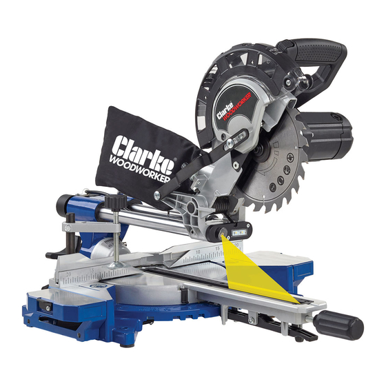
- Page 1 216MM SLIDING MITRE SAW MODEL NO: CMS216S PART NO: 6461525 OPERATION & MAINTENANCE INSTRUCTIONS ORIGINAL INSTRUCTIONS GC0421...
- Page 2 INTRODUCTION Thank you for purchasing this CLARKE Sliding Mitre Saw. Before attempting to use this product, please read this manual thoroughly and follow the instructions carefully. In doing so you will ensure the safety of yourself and that of others around you, and you can look forward to your purchase giving you long and satisfactory service.
-
Page 3: Safety Warnings
SAFETY WARNINGS WORK AREA 1. Keep the work area clean and well lit. Cluttered and dark areas invite accidents. 2. DO NOT operate power tools in explosive atmospheres, such as in the presence of flammable liquids, gases or dust. Power tools create sparks which may ignite the dust or fumes. -
Page 4: Additional Safety Rules For Mitre Saws
5. DO NOT overreach. Keep proper footing and balance at all times. This enables better control of the power tool in unexpected situations. 6. Dress properly. Do not wear loose clothing or jewellery. Keep your hair, clothing and gloves away from moving parts. Loose clothes, jewellery or long hair can be caught in moving parts. - Page 5 3. DO NOT feed the workpiece into the blade or cut "freehand" in any way. Unrestrained or moving workpieces could be thrown at high speeds, causing injury. 4. Push the saw through the workpiece. DO NOT pull the saw through the workpiece.
- Page 6 EN 847-1. 5. DO NOT use saw blades made of high-speed alloy steel (HSS steel). Only use replacement blades from your CLARKE dealer. 6. Observe the saw blade direction of rotation. 7. Clean any grease, oil and water off of the clamping surfaces.
-
Page 7: Laser Safety
8. ONLY use the saw blade supplied for cutting wood, never for the cutting of metals. 9. ONLY use saw blades with diameters in accordance with the markings on the saw. 10. Use additional workpiece supports, if required for workpiece stability. 11. -
Page 8: Residual Risks
RESIDUAL RISKS 1. Despite all precautions having been met, some non-obvious residual risks may still remain. 2. Residual risks can be minimised if the safety warnings are observed along with the whole of the operating instructions. 3. DO NOT load the machine unnecessarily. Excessive pressure when sawing will quickly damage the saw blade which results in reduced output of the machine in the processing and in cut precision. -
Page 9: Safety Symbols
SAFETY SYMBOLS Read instruction manual and safety instructions Wear safety goggles Wear ear defenders Wear a dust mask Important! Risk of injury. Never touch the moving saw blade! Laser Radiation, Class 2 Laser: Do not stare into the beam. Protection Class II (double shielded) Parts &... -
Page 10: Electrical Connections
ELECTRICAL CONNECTIONS WARNING: READ THESE ELECTRICAL SAFETY INSTRUCTIONS THOROUGHLY BEFORE CONNECTING THE PRODUCT TO THE MAINS SUPPLY. Before switching the product on, make sure that the voltage of your electricity supply is the same as that indicated on the rating plate. This product is designed to operate on 230VAC 50Hz. - Page 11 OVERVIEW Parts & Service: 020 8988 7400 / E-mail: Parts@clarkeinternational.com or Service@clarkeinternational.com...
-
Page 12: Before Use
MITRE SAW STAND ( NOT SUPPLIED You can also mount the machine to a mitre saw stand available from your local CLARKE dealer. CUTS Mitre Saw Stand Part No 6500944. Parts & Service: 020 8988 7400 / E-mail: Parts@clarkeinternational.com or Service@clarkeinternational.com... -
Page 13: Locking / Releasing The Saw Head
LOCKING / RELEASING THE SAW HEAD 1. Push down slightly on the operating handle and pull out the head locking pin and rotate it 90° degrees as shown so that the small pin rests on the grooves that hold the head locking pin in the unlocked position. -
Page 14: Operation
OPERATION ALWAYS follow the safety instructions and applicable regulations. BODY AND HAND POSITION Correct positioning of your body and hands when you operate the mitre saw will make cutting easier and safer. • DO NOT put your hands near the blade. •... -
Page 15: Basic Saw Cuts
BASIC SAW CUTS VERTICAL STRAIGHT CROSS CUT 1. Check and adjust the mitre table angles are correct as shown on page 21/ 2. Release the slide rail lock, and push the saw head back to the rear position. 3. Retighten the slide rail lock. 4. -
Page 16: Performing A Sliding Cut
PERFORMING A SLIDING CUT The slide rail lets you cut larger workpieces up to 340mm x 65mm using an out- down-back sliding motion. 1. Release the slide rail lock. 2. Push the trigger release (1) with your thumb and squeeze the trigger (2). - Page 17 PERFORMING A MITRE CUT 1. To adjust the mitre saw table, loosen the handle approximately 2 turns counter clockwise. 2. Pull up the locking lever. 3. Turn the table and pointer to the necessary angle (0° to 45° left or right).
-
Page 18: Bevel Cuts
BEVEL CUTS Bevel angles can be set from 45° left to vertical. 1. Loosen the bevel adjustment handle. 2. Set the bevel to the correct angle as shown on the scale. 3. Tighten the bevel adjustment handle. 4. Continue as for a vertical straight cross-cut. - Page 19 LIMITING THE DEPTH OF CUT (GROOVE CUTTING) 1. Subtract the depth of your groove from the thickness of your workpiece. • This will give you the height above the table surface at which the saw blade must be set. • For example if you want a 6 mm deep groove in a 18 mm thick piece of wood, you need a saw blade height of 12mm (18mm - 6mm).
-
Page 20: The Laser Guide
THE LASER GUIDE Laser Radiation, Class 2 Laser: Do not stare into the beam. TO SWITCH ON: 1. Push the laser ON/OFF switch once. • A laser line is projected onto the material, providing an accurate guide for the cut. TO SWITCH OFF: 1. - Page 21 ADJUSTMENTS CHECK AND ADJUST THE MITRE ANGLE 1. Lock the saw head in the down position see page 13. 2. Put a set square up against the left side of the fence and blade. 3. Adjust the mitre arm if necessary until the blade is perfectly square to the fence.
- Page 22 90 DEGREE STOP ADJUSTMENT 4. Put a set square on the table and up against the blade. NOTE: DO NOT touch the tips of the blade teeth with the square. If adjustment is necessary, continue as follows: 5. Loosen the lock nut and turn the 90°...
-
Page 23: Maintenance
MAINTENANCE WARNING: MAKE SURE THAT THE SAW IS SWITCHED OFF AND UNPLUGGED FROM THE MAINS SUPPLY BEFORE FITTING OR REMOVING THE BLADE. WARNING: WEAR SAFETY GLOVES WHEN CHANGING THE SAW BLADE. WARNING: THE REPLACEMENT BLADE MUST BE RATED TO AT LEAST 4700 RPM. -
Page 24: Replacing The Table Insert
4. Depress the blade lock and slowly rotate the retaining screw using the hex key in clockwise direction. • The blade lock engages after no more than one rotation • WARNING: NEVER PUSH THE BLADE LOCK IN WHEN THE MOTOR IS RUNNING. 5. -
Page 25: Changing The Carbon Brushes
CHANGING THE CARBON BRUSHES WARNING: MAKE SURE THAT THE SAW IS SWITCHED OFF AND UNPLUGGED FROM THE MAINS SUPPLY BEFORE INSPECTING OR CHANGING THE CARBON BRUSHES. After extensive use, the carbon brushes will become worn and should be checked if the motor seems to be lacking power. Replacements are available from your dealer. -
Page 26: Specifications
SPECIFICATIONS Model Number CMS216S Part Number 6461525 Rated Voltage 230 V AC @ 50Hz Input Wattage 2000 W Ingress protection IP 0X Blade Diameter 216 mm Blade bore 30 mm Max. blade thickness 2.8 mm Max. no load machine speed 4700 rpm Max. -
Page 27: Exploded Diagram
EXPLODED DIAGRAM Parts & Service: 020 8988 7400 / E-mail: Parts@clarkeinternational.com or Service@clarkeinternational.com... -
Page 28: Parts List
PARTS LIST No Description No Description Base Countersunk screw Rear support bar Pan head screw Socket set screw M6 x 8 Bar lock spring Hexagon bolt M8 x 20 Switch trigger spring Left fence Lock knob Butterfly screw Disc locking lever Cross recessed pan head screw Side handle M6 x 15 wing screw... - Page 29 No Description No Description Screw M5 x 16 Screw Gland Side plate (Large hood) Bearing 6003Z2 Large Hood Cover plate 100 Pulley wheel Output shaft 101 Transparent cover Woodruff key 102 N/a Large gear 103 Transparent cover coat hood Bearing retainer 104 Cross head pan head s/t screw Needle roller bearing 105 Lifting handle...
- Page 30 No Description No Description 131 Laser transparent cover 139 Clamping block 132 LED lamp holder 140 Fixed link 133 Countersunk screw 141 Handwheel 134 Foot 142 Fixed rod cover 135 n/a 143 Dust bag 136 n/a 144 3mm Hex key 137 Screw M5 x 7 145 6mm Hex key 138 Locking disc...
-
Page 31: Declaration Of Conformity
DECLARATION OF CONFORMITY Parts & Service: 020 8988 7400 / E-mail: Parts@clarkeinternational.com or Service@clarkeinternational.com...
Need help?
Do you have a question about the CMS216S and is the answer not in the manual?
Questions and answers