
Related Manuals for Clarke CTS11


Summary of Contents for Clarke CTS11
- Page 1 © 1206 10” TABLE SAW 10” TABLE SAW Model CTS11 Model CTS11 Part Number 6500750 Operating & Maintenance Instructions...
-
Page 3: Table Of Contents
Thank you for purchasing your new CLARKE 10” TABLE SAW, which is designed for DIY, and hobby use ONLY. Before attempting to operate this machine, please read this instruction manual thoroughly and follow all directions carefully. In doing so you will ensure the safety of both yourself and others around you, and, at the same time, you should look forward to it providing long and trouble free service. -
Page 4: Specifications
SPECIFICATIONS Model No ..........CTS11 Part No........... 6500753 Motor ............. 230V~ 50Hz 1ph Power rating ......1.5Kw Speed ........4435 rpm Fuse rating ......... 13 Amps Saw Blade ..........10” dia. (254x16mm) TCT Maximum depth of cut at 0 .... -
Page 5: Safety Instructions
SAFETY INSTRUCTIONS KEEP WORK AREA CLEAN : Cluttered areas and benches invite injuries. CONSIDER WORK AREA ENVIRONMENT: Do not expose power tools to rain. Do not use power tools in damp, or wet locations. Keep the work area well lit. Do not use this saw in the presence of flammable liquids or gases. - Page 6 SAFETY INSTRUCTIONS USE OUTDOOR EXTENSION LEADS: When the tool is used outdoors, use only extension leads intended for outdoor use and so marked. Always make sure that the extension lead is suitably rated for the tool. Position the extension lead so that it does not create a hazard. STAY ALERT: Watch what you are doing.
- Page 7 SAFETY INSTRUCTIONS USE THE MITRE GAUGE: Always hold the work firmly against the mitre gauge fence when cross cutting. LOCK THE GUIDES: Always ensure the rip fence guide is securely fastened when in use. USE A PUSH STICK: Use a push-stick to feed the workpiece past the saw blade. The push stick should always be stored with the machine when not in use.
-
Page 8: Electrical Connections
ELECTRICAL CONNECTIONS WARNING! THIS APPLIANCE MUST BE EARTHED. Connect the mains lead to a 230 volt (50Hz) domestic electrical supply via a standard 13 amp BS 1363 plug fitted with a 13 amp fuse, or a suitably fused isolator switch. IMPORTANT: The wires in the mains lead are coloured in accordance with the following code: Green &... -
Page 9: Features
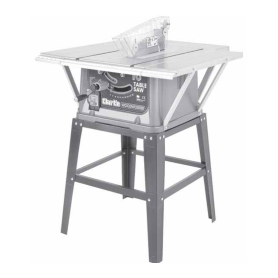
MUST be firmly secured to either a workbench or a stand to ensure its complete stability. NOTE: The stand illustrated is designed specifically for the CTS11 and is available from your Clarke dealer. 5. The blade height adjuster raises or lowers the blade. -
Page 10: Glossary Of Terms
GLOSSARY OF TERMS Crosscut A cutting operation made across the width of the workpiece - across the grain. Featherboard A device which can help guide workpieces during rip type operation. Heel Misalignment of the blade. Kerf The amount of material removed by the blade in a through cut. Kickback An uncontrolled grabbing, and throwing of the workpiece back toward the front of the saw during a rip type operation. -
Page 11: Unpacking And Checking Contents
Separate all parts from the packing materials and check to ensure that all components are accounted for, according to the following list, before discarding any packing material. Fig.2 Should any component be missing or damaged in transit, please contact your CLARKE dealer immediately, or CLARKE Customer Service Department on 020 8558 7400 WARNING! DO NOT plug the table saw into the mains until it is fully assembled and checks made according to these instructions. -
Page 12: Assembly
ASSEMBLY IMPORTANT: Take great care to avoid contact with the saw teeth which are extremely sharp when performing the following operations. Handle Fig. 3 Attach the handle to the blade angle adjuster as shown. Use the screw to secure the handle to the shaft. Table Extensions Lower the blade as far as possible. - Page 13 Riving Knife Fig. 5 Remove the table insert. Raise the blade as far as possible. You may find it helpful to adjust the blade angle, so that the blade lays on its side. Slide the Riving Knife into position, and adjust the Riving knife so that a clearance of no more than 5mm exists between blade and knife, and along the full length of the riving knife, as shown in Fig.
-
Page 14: Fitting The Blade Guard
Fitting The Blade Guard Fig. 8 Raise the saw blade as far as possible. Attach the blade guard to the riving knife, as shown. • The guard should be secure, but capable of dropping under its own weight. Rip Fence The rip fence has the following parts: A. - Page 15 Dust Outlet Fig. 11 Connect a vacuum cleaner hose to the dust outlet port on the rear of the table saw.
-
Page 16: Mounting The Saw
A Floor Stand, specially designed for your CTS11 Table Saw is available from your CLARKE dealer . opening... - Page 17 NOTE: For proper stability, holes must be counter sunk on the underside of the plywood so that screw heads are flush with the bottom surface of the mounting board. IMPORTANT Ensure the Bottom Grid is in place when bolting the machine to the workbench. Securely clamp the board to a workbench Fig.13 using two or more “G”...
-
Page 18: Important Checks Before Starting
IMPORTANT CHECKS - BEFORE STARTING IMPORTANT: Before attempting to use the machine, it is necessary to ensure the various components are correctly adjusted, and securly fitted. • MAke sure the Saw is fitted to the bench or stand securely. • Make sure that the blade is securly fitted. -
Page 19: Adjustments
Overload Cut-Out Your machine also features an overload cut-out device, so that if the machine is overloaded (due to feed pressure being too great, a dull blade or low voltage etc.), the overload relay will intervene and the motor will automatically cut out. In this event: a. -
Page 20: Using The Mitre Gauge
Using The Mitre Gauge Fig. 16 Slide the securing bolts into the slot on the fence as shown. Slide the mitre gauge assembly into one of the slots on the table. Loosen the Locking knob and set the mitre gauge to the required angle. -
Page 21: Adjusting The Rip Fence
Adjusting The Rip Fence Fig. 19 Lift the fence handle up. Slide the rip fence to the position you require. Push the fence handle down to lock into place. -
Page 22: Cutting Methods
CUTTING METHODS Ripping Or Rip Cutting Fig. 20 Ripping means to cut a piece of timber in the same direction as the grain, i.e. usually lengthwise. • The rip fence can be positioned to the right or left of the saw blade, and can be adjusted to suit the width of cut required, Lock the rip fence into position. -
Page 23: Push Stick And Push Block
Push Stick And Push Block Fig.24 Make the Push Block using pieces of 10mm plywood 304mm and 19mm hardwood as shown in Fig.24. • The small piece of wood 10x10x64mm should be GLUED to the plywood. DO NOT USE NAILS or SCREWS. -
Page 24: Repetitive Cutting
CROSSCUTTING TIPS Do not make cuts freehand (without using the mitre gauge or other auxiliary device) the blade may bind in the cut and cause kickback or cause your fingers or hand to slip into the blade. Always lock the mitre gauge when in use. Remove rip fence from table when not in use. -
Page 25: Mitre Cutting
Mitre Cutting Fig. 29 Mitre cutting is the term used for cutting at an angle other than 90 to the edge of the wood. Adjust the mitre gauge to the desired angle, and lock it. • The mitre gauge may be used in either of the grooves in the table. -
Page 26: Maintenance
You may apply a coat of wax to the table to keep the surface clean and allow wood being cut to slide more freely. Changing The Blade • Use only Clarke Blades, (see parts list for part numbers). • Replace the blade when teeth become damaged or dull. WARNING! TO PREVENT PERSONAL INJURY, ALWAYS DISCONNECT PLUG FROM POWER SOURCE BEFORE CHANGING BLADES. -
Page 27: Renewal Motor Brush
Renewing Motor Brushes WARNING! ENSURE THE PLUG IS DISCONNECTED FROM THE POWER SUPPLY BEFORE PROCEEDING • Lower the blade to minimum height and remove the riving knife and blade guard. • Turn the table saw over so that it rests on its table top . Remove the bottom grill by removing the 6 screws shown. -
Page 28: Trouble Shooting
TROUBLE SHOOTING TROUBLE PROBABLE CAUSE REMEDY Saw will not start 1. Saw not plugged in 1. Plug in the machine 2. Fuse blown or circuit breaker 2. Replace fuse or reset circuit tripped breaker 3. Power cable damaged 3. Have cable replaced by authorised service centre Material Pinches 1. -
Page 29: Parts Lists And Diagrams
PARTS LISTS No. Description Part No No. Description Part No Locking nut M6 HTCTS11001 End cover HTCTS11039 Flat washer HTCTS11002 Fence HTCTS11040 Left board HTCTS11003 End cover HTCTS11041 Guard support HTCTS11004 Screw M4×10 HTCTS11042 Elastic pin HTCTS11005 HTCTS11043 Right board HTCTS11006 Locking base HTCTS11044... -
Page 30: Parts And Service Contacts
HTCTS11107 PARTS AND SERVICE CONTACTS For Spare Parts and Service, please contact your nearest dealer, or CLARKE International, on one of the following numbers. PARTS & SERVICE TEL: 020 8988 7400 PARTS & SERVICE FAX: 020 8558 3622 or e-mail as follows: PARTS: Parts@clarkeinternational.com... -
Page 31: Parts Diagram
PARTS DIAGRAM Fig.37...
Need help?
Do you have a question about the CTS11 and is the answer not in the manual?
Questions and answers