
Related Manuals for Clarke Woodworker CTS10C


Summary of Contents for Clarke Woodworker CTS10C
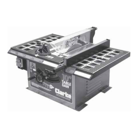
- Page 1 © 0900 10” TABLE SAW Model CTS10C Part Number 6500750 Operating & Maintenance Instructions PRODUCT SERIAL/BATCH NO......
-
Page 3: Table Of Contents
Thank you for purchasing your new CLARKE 10” TABLE SAW, which is designed for DIY, and hobby use ONLY. Before attempting to operate this machine, please read this instruction manual thoroughly and follow all directions carefully. In doing so you will ensure the safety of both yourself and others around you, and, at the same time, you should look forward to it providing long and trouble free service. -
Page 4: Specifications
SPECIFICATIONS Model No ..........CTS10C Part No........... 6500750 Motor ............. 230V~ 50Hz 1ph Power rating ......1.4Kw Speed ........4800 rpm Fuse rating ......... 13Amps Saw Blade ..........10” dia. - 5/8” bore (254x16mm) TCT Maximum depth of cut ......75mm Weight ........... -
Page 5: General Safety Rules
GENERAL SAFETY RULES WARNING As with all machinery, there are certain hazards involved with their operation and use. Exercising respect and caution will considerably lessen the risk of personal injury. However, if normal safety precautions are overlooked or ignored, personal injury to the operator or damage to property may result. READ AND BECOME FAMILIAR with the entire operating manual. -
Page 6: Additional Safety Rules For Table Saws
19. SECURE THE WORK. Use clamps to hold accessories when practical. It’s safer than using your hand. 20. DON’T OVERREACH. Keep your proper footing and balance at all times. For best footing wear rubber soled shoes or boots. Keep the floor clear of oil, scrap wood, etc. 21. -
Page 7: Electrical Connections
ELECTRICAL CONNECTIONS WARNING! THIS APPLIANCE MUST BE EARTHED. Connect the mains lead to a 230 volt (50Hz) domestic electrical supply via a standard 13 amp BS 1363 plug fitted with a 13 amp fuse, or a suitably fused isolator switch. IMPORTANT: The wires in the mains lead are coloured in accordance with the following code: Green &... -
Page 8: Features
FEATURES Blade Guard Riving Knife Table Insert Fig.1 Rip Fence Mitre Gauge Table Switch Panel Dust Extraction Outlet Mounting Hole Blade tilt Scale Blade Tilt Locking Knob Blade height Adj Wheel The switch panel incorporates the ON and OFF switches, and an overload reset button. Your saw also features an Overload Protection device, so that if the motor is overloaded (due to feed pressure being too great, dull blade or low voltage), the Overload Relay will intervene, and the motor will automatically cut out. -
Page 9: Glossary Of Terms
The Rip Fence is for use when rip cutting timber. It can be easily moved or locked in place by screwing IN the locking handle. Take care NOT to overtighten the locking handle. The Blade Guard protects the operator and must ALWAYS be in place and working properly. -
Page 10: Unpacking And Checking Contents
Separate all parts from the packing materials and check to ensure that all components are accounted for, according to the following list, before discarding any packing material. Should any component be missing or damaged in transit, please contact your CLARKE dealer immediately, or CLARKE Customer Service Department on 020 8556 4443. -
Page 11: Assembly Instructions
ASSEMBLY Before the machine can be used, the loose parts must first be assembled to it, and certain adjustments carried out. Please proceed as follows: A. The Saw Blade WARNING! EXERCISE EXTREME CARE WHEN HANDLING THE SAW BLADE. THE TEETH ARE EXTREMELY SHARP AND CARELESSNESS COULD CAUSE SEVERE PERSONAL INJURY. - Page 12 WARNING! NEVER START THE MACHINE WITH THE BLADE GUARD REMOVED. C. Rip Fence Remove and discard the shipping nut from the threaded rod on the front end of the fence clamp bracket and thread the fence locking handle on to the threaded rod. Place the fence on the table.
-
Page 13: Mounting The Saw
If the table saw is to be used in a permanent location, it should be fastened securely to a firm supporting surface such as a stand or workbench, using the four mounting holes in the base. A Floor Stand, specially designed for your CTS10C Table Saw is available from your CLARKE dealer . Fig.6 286mm (11.25”) -
Page 14: Important Checks Before Starting
NOTE: For proper stability, holes must be counter sunk on the underside of the plywood so that screw heads are flush with the bottom surface of the mounting board. IMPORTANT Ensure the Bottom Grid is in place when bolting the machine to the workbench. Securely clamp the board to a workbench Fig.7 using two or more “G”... -
Page 15: Work Helpers
2. The Saw Blade Fig.9 Check to ensure the blade is sound. If teeth Blade Guard are chipped, or cracks are apparent, it must Blade Riving Knife Bracket Kerf be renewed. 3. The Blade Guard Ensure the Blade Guard is in place, pivots freely, and falls under its own weight. -
Page 16: Operating Instructions
Auxiliary Fence 445mm 19mm 10mm Make one using pieces of 10mm plywood and 19mm hardwood. Fasten together with glue and wood screws. Dimensions are shown in Fig. NOTE: Since the Push Block is used with the Auxiliary Fence, Auxiliary Fence the 120mm dimensions must be held identical on both the pieces. - Page 17 Additionally, when positioning the fence for maximum rip, make sure it is fully clamped, and does not extend beyond the edge of the table. Do not rip or cut mouldings with the fence beyond this position, because it cannot be locked. When ripping, you should ALWAYS abide by the following rules: Never make these cuts FREEHAND (without using the rip fence or auxiliary devices when required) because the blade could bind in the cut and cause a KICKBACK.
- Page 18 When the width of rip is 150mm (6”) and wider Fig.13 use your RIGHT HAND to FEED the workpiece, use LEFT HAND only to GUIDE the workpiece, do not feed the workpiece with the left hand. (Fig.13). When width of rip is 50 - 150mm (2”- 6”) wide use a push stick to feed the work.
-
Page 19: Crosscutting
4. Crosscutting Crosscutting is the term used to describe cuts made in timber across the grain. This type of cut requires the use of the MITRE GAUGE. This includes bevel cutting, mitre cutting and compound mitre cutting (described later in this paragraph). To perform a cross cutting operation, the Fig.17 work is firmly held against the mitre gauge... -
Page 20: Repetitive Cutting
Notches are provided in the mitre gauge head for Fig.19 attaching an AUXILIARY FACING to make it easier to cut longer pieces. Ensure the facing does not extend so far as to interfere with the proper operation of the Saw Blade Guard. Select a suitable piece of smooth straight wood, drill two holes through it and attach it with screws. -
Page 21: Mitre Cutting
Fig.20 Slide the workpiece along the mitre gauge until it touches the block, hold it securely. When cutting long workpieces, make sure the end is supported - from the floor. Make the cut, pull the workpiece back and push the cut-off piece off the table with a long push stick, DO NOT ATTEMPT TO PICK IT UP AS THIS COULD Repetitive cutting... -
Page 22: Compound Mitre Cutting
8. Compound Mitre Cutting Compound mitre cutting is a combination of mitre cutting and bevel crosscutting. The cut is made at an angle other than 90 to both the edge and the flat side of the wood. Adjust the mitre gauge and the blade to the desired angle, and ensure the mitre gauge body is locked. -
Page 23: Changing The Saw Blade
2. Changing the Blade This procedure is explained on page 10 under ‘Assembly’. IMPORTANT: 1. Use only Clarke Blade, Part No. 6503125. 2. Replace the blade when teeth become damaged or dull. WARNING! 1. TO PREVENT PERSONAL INJURY, ALWAYS DISCONNECT PLUG FROM POWER SOURCE BEFORE CHANGING BLADES. -
Page 24: Adjusting 90 And 45 Degree Positive Stops
4. Adjusting 90 and 45 Degree Positive Stops WARNING! ENSURE THE PLUG IS DISCONNECTED FROM THE POWER SUPPLY BEFORE PROCEEDING 4A. Adjusting Positive Stop at 90 Degrees Raise the blade to maximum height. Fig.26 (ii) Loosen the blade tilt lock handle, push the elevation wheel to the left as far as possible and tighten the blade tilt locking knob. -
Page 25: Trouble Shooting
TROUBLE SHOOTING TROUBLE PROBABLE CAUSE REMEDY Saw will not start 1. Saw not plugged in 1. Plug in the machine 2. Fuse blown or circuit breaker 2. Replace fuse or reset circuit tripped breaker 3. Power cable damaged 3. Have cable replaced by authorised service centre Does not make 1. -
Page 26: Parts Lists And Diagrams
PARTS LISTS Blade Guard Assembly No. Description Part No 14913301 Push Nut Anti-Kickback Pawl 14913101 Spacer 14913201 Spring 14913401 Roll Pin Guard 14912901 Spacer 14912801 Hex Nut Flat Washer Hex Screw Guard Arm 14912301 Push Nut Bushing Blade Guard 149122021 Bolt M6 x 55mm Flat Washer 6mm Guard Support... - Page 27 No. Description Part No No. Description Part No Label Bracket 15106101 Screw Rod 1510021 Bracket 15106201 Saddle 14921001 Spring Pin Hex Bolt M6 x 55mm Screw Int Tooth Washer Handle 14008302 Nut Hex Guard Support Hand Wheel 14900601 Flat Washer Knob 15100801 Motor...
- Page 28 PARTS DIAGRAM...
Need help?
Do you have a question about the Woodworker CTS10C and is the answer not in the manual?
Questions and answers