
Related Manuals for Clarke CMS210


Summary of Contents for Clarke CMS210
- Page 1 210MM (8”) MITRE SAW MODEL NO: CMS210 PART NO: 6500756 OPERATION & MAINTENANCE INSTRUCTIONS LS0716...
- Page 2 INTRODUCTION Thank you for purchasing this CLARKE 210mm (8”) Mitre Saw. Before attempting to use this product, please read this manual thoroughly and follow the instructions carefully. In doing so you will ensure the safety of yourself and that of others around you, and you can look forward to your purchase giving you long and satisfactory service.
-
Page 3: General Safety Rules
GENERAL SAFETY RULES 5. If operating the power tool in a WORK AREA damp location is unavoidable, 1. Keep the work area clean and use a residual current device well lit. Cluttered and dark areas (RCD) protected supply. invite accidents. PERSONAL SAFETY 2. -
Page 4: Additional Safety Rules For Mitre Saws
GENERAL SAFETY RULES and any other condition that may 6. Dress properly. Do not wear loose affect the power tools operation. clothing or jewellery. Keep your If damaged, have the power tool hair, clothing and gloves away repaired before use. Many from moving parts. - Page 5 11. Do not use any abrasive discs. mitre saw stand available from your local Clarke dealer. 12. Raise the blade from the kerf in the workpiece prior to releasing the switch. 13. Ensure that the arm is securely fixed when performing bevel cuts.
-
Page 6: Safety Symbols
SAFETY SYMBOLS Wear eye protection Wear dust mask Wear ear defenders Do not put your hand near the blade Read instruction manual before use Laser Radiation, Class 2 Laser: Do not stare into the beam. Parts & Service: 020 8988 7400 / E-mail: Parts@clarkeinternational.com or Service@clarkeinternational.com... -
Page 7: Electrical Connections
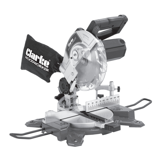
ELECTRICAL CONNECTIONS WARNING! Read these electrical safety instructions thoroughly before connecting the product to the mains supply. Before switching the product on, make sure that the voltage of your electricity supply is the same as that indicated on the rating plate. This product is designed to operate on 230VAC 50Hz. - Page 8 OVERVIEW Parts & Service: 020 8988 7400 / E-mail: Parts@clarkeinternational.com or Service@clarkeinternational.com...
-
Page 9: Before Use
MITRE SAW STAND ( NOT SUPPLIED You can also mount the machine to a purpose built mitre saw stand available from your local Clarke dealer. Parts & Service: 020 8988 7400 / E-mail: Parts@clarkeinternational.com or Service@clarkeinternational.com... -
Page 10: Locking / Releasing The Saw Head
LOCKING / RELEASING THE SAW HEAD 1. Press down slightly on the operating handle and pull out the Head Lock Pin. 2. Gently release the downward pressure on the operating handle and allow the head to rise to its full height. -
Page 11: Body And Hand Position
INSTRUCTIONS FOR USE Always observe the safety instructions and applicable regulations. BODY AND HAND POSITION Proper positioning of your body and hands when operating the mitre saw will make cutting easier and safer. • Never place your hands near the cutting area or blade. •... -
Page 12: Basic Saw Cuts
BASIC SAW CUTS VERTICAL STRAIGHT CROSS CUT 1. Release the table mitre lock and move the arm to the 0° position and re-tighten the table mitre lock. 2. Place the wood to be cut against the fence. 3. Grasp the operating handle and press and hold the blade guard release lever (1) to release the head. -
Page 13: Mitre Cross-Cut
MITRE CROSS-CUT 1. Release the table mitre lock and move the arm left or right to the required angle. 2. Lock in position by tightening the table mitre lock. • Always ensure that the table mitre lock is securely tightened before cutting. -
Page 14: Compound Mitre Cuts
COMPOUND MITRE CUTS A compound mitre is a cut made using a mitre angle and a bevel angle at the same time. This is the type of cut used to make frames or boxes with slanting sides. 1. Set your saw to the required angles and make a few trial cuts. -
Page 15: The Laser Guide
THE LASER GUIDE Your saw is fitted with a laser guide to assist with accurate cutting. Laser Radiation, Class 2 Laser: Do not stare into the beam. SWITCHING ON/OFF Switch the laser on/off using the on/ off switch. REPLACING THE BATTERIES 1. -
Page 16: Checking And Adjusting The Mitre Settings
ADJUSTMENTS WARNING: MAKE SURE THAT THE SAW IS SWITCHED OFF AND UNPLUGGED FROM THE MAINS SUPPLY BEFORE PERFORMING ANY ADJUSTMENTS. CHECKING AND ADJUSTING THE MITRE SETTINGS 1. Release the blade guard release lever to release the mitre arm. 2. Lower the head until the blade just enters the kerf plate. -
Page 17: Maintenance
5. Replace the blade, ensuring it has the correct diameter and bore. • Make sure that the teeth point down at the front as shown above. • Please note that spare blades are available from Clarke International. Please see your Clarke dealer. -
Page 18: Changing The Carbon Brushes
CHANGING THE CARBON BRUSHES WARNING: MAKE SURE THAT THE SAW IS SWITCHED OFF AND UNPLUGGED FROM THE MAINS SUPPLY BEFORE CHANGING THE CARBON BRUSHES. A spare pair of carbon brushes are supplied with the machine. Should it become necessary to change these: 1. -
Page 19: Specifications
662 x 736 x 420 mm Weight 7.6 kg To obtain the stated cutting capacities, always use 210 mm saw blades with a 30 mm bore, available from your local Clarke dealer. Parts & Service: 020 8988 7400 / E-mail: Parts@clarkeinternational.com or Service@clarkeinternational.com... -
Page 20: Exploded Diagram
EXPLODED DIAGRAM Parts & Service: 020 8988 7400 / E-mail: Parts@clarkeinternational.com or Service@clarkeinternational.com... -
Page 21: Parts List
PARTS LIST PARTS NAME PARTS NAME Fixed Guard M5 Locking Nut 6000z Bearing Flange Shaft Locking Sets Transparent Movable Guard Windshield Tower Type Spring Self Tapping Screw Ø5 Spring Washer Stator 1400w Connecting Block Rotor 1400w M5x10 Screw 608z Bearing Cover On Fixed Guard Label Screw For Fixing Connecting Bar... - Page 22 PARTS NAME PARTS NAME Locking Button 114 Metal Rod O-ring Ø8.6xø5xø1.8 115 Mitre Cutting Adjusting Base Locking Rod 116 45° Indication Plate Position Limiting Shaft 117 Inner Hex Screw M6x20 Self Tapping Screw M4x12 118 Ø6 Spring Washer Lower Guard 119 Ø6 Plain Washer Torsion Spring 120 Movable Table Locking Screw...
-
Page 23: Declaration Of Conformity
DECLARATION OF CONFORMITY Parts & Service: 020 8988 7400 / E-mail: Parts@clarkeinternational.com or Service@clarkeinternational.com...
Need help?
Do you have a question about the CMS210 and is the answer not in the manual?
Questions and answers