
Related Manuals for Clarke Woodworker CMS10S2B


Summary of Contents for Clarke Woodworker CMS10S2B
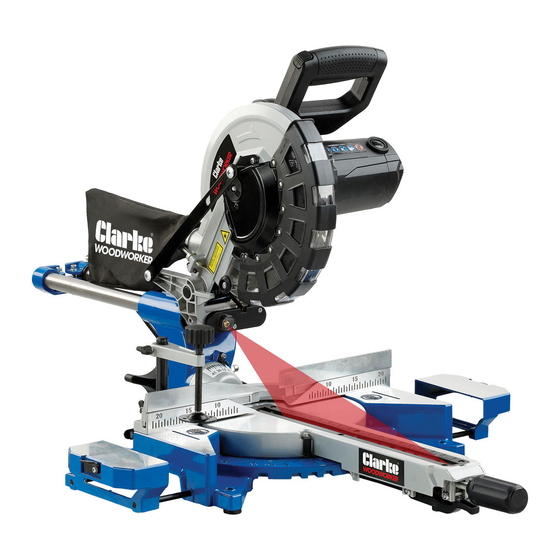
- Page 1 10”(255MM) SLIDING MITRE SAW MODEL NO: CMS10S2B PART NO: 6461515 OPERATION & MAINTENANCE INSTRUCTIONS ORIGINAL INSTRUCTIONS GC1020- ISS 1...
- Page 2 INTRODUCTION Thank you for purchasing this CLARKE Mitre Saw. Before attempting to use this product, please read this manual thoroughly and follow the instructions carefully. In doing so you will ensure the safety of yourself and that of others around you, and you can look forward to your purchase giving you long and satisfactory service.
-
Page 3: Safety Warnings
SAFETY WARNINGS WORK AREA 1. Keep the work area clean and well lit. Cluttered and dark areas invite accidents. 2. DO NOT operate power tools in explosive atmospheres, such as in the presence of flammable liquids, gases or dust. Power tools create sparks which may ignite the dust or fumes. -
Page 4: Additional Safety Rules For Mitre Saws
5. Do not overreach. Keep proper footing and balance at all times. This enables better control of the power tool in unexpected situations. 6. Dress properly. Do not wear loose clothing or jewellery. Keep your hair, clothing and gloves away from moving parts. Loose clothes, jewellery or long hair can be caught in moving parts. - Page 5 3. DO NOT feed the workpiece into the blade or cut "freehand" in any way. Unrestrained or moving workpieces could be thrown at high speeds, causing injury. 4. Push the saw through the workpiece. Do not pull the saw through the workpiece.
- Page 6 EN 847-1. 6. DO NOT use saw blades made of high-speed alloy steel (HSS steel). Only use replacement blades from your CLARKE dealer. 7. Observe the saw blade direction of rotation. 8. Clean any grease, oil and water off of the clamping surfaces.
-
Page 7: Laser Safety
9. ONLY use the saw blade supplied for cutting wood, never for the cutting of metals. 10. ONLY use saw blades with diameters in accordance with the markings on the saw. 11. Use additional workpiece supports, if required for workpiece stability. 12. -
Page 8: Residual Risks
RESIDUAL RISKS 1. Despite all precautions having been met, some non-obvious residual risks may still remain. 2. Residual risks can be minimised if the "safety instructions" and the "Proper use" are observed along with the whole of the operating instructions. 3. -
Page 9: Safety Symbols
SAFETY SYMBOLS Read instruction manual and safety instructions Wear safety goggles! Wear ear defenders Wear a dust mask Important! Risk of injury. Never touch the moving saw blade! Laser Radiation, Class 2 Laser: Do not stare into the beam. Protection Class II (double shielded) Parts &... -
Page 10: Electrical Connections
ELECTRICAL CONNECTIONS WARNING: READ THESE ELECTRICAL SAFETY INSTRUCTIONS THOROUGHLY BEFORE CONNECTING THE PRODUCT TO THE MAINS SUPPLY. Before switching the product on, make sure that the voltage of your electricity supply is the same as that indicated on the rating plate. This product is designed to operate on 230VAC 50Hz. - Page 11 OVERVIEW Parts & Service: 020 8988 7400 / E-mail: Parts@clarkeinternational.com or Service@clarkeinternational.com...
-
Page 12: Before Use
MITRE SAW STAND ( NOT SUPPLIED You can also mount the machine to a mitre saw stand available from your local CLARKE dealer. CUTS Mitre Saw Stand part No 6500944 Parts & Service: 020 8988 7400 / E-mail: Parts@clarkeinternational.com or Service@clarkeinternational.com... -
Page 13: Locking / Releasing The Saw Head
LOCKING / RELEASING THE SAW HEAD 1. Push down slightly on the operating handle and pull out the head locking pin and rotate it 90° degrees as shown so that the small pin rests on the grooves that hold the head locking pin in the unlocked position. -
Page 14: Operation
OPERATION Always obey the safety instructions and applicable regulations. BODY AND HAND POSITION Correct positioning of your body and hands when you operate the mitre saw will make cutting easier and safer. • Do not put your hands near the blade. •... -
Page 15: Basic Saw Cuts
BASIC SAW CUTS VERTICAL STRAIGHT CROSS CUT 1. Adjust the mitre table to 0° as shown on page 17. 2. Release the slide rail lock, and push the saw head back to the rear position. 3. Retighten the slide rail lock. 4. -
Page 16: Performing A Sliding Cut
PERFORMING A SLIDING CUT The slide rail lets you cut larger workpieces up to 340 mm x 90 mm using an out- down-back sliding motion. 1. Release the slide rail lock. 2. Push the trigger release (1) with your thumb and squeeze the trigger (2). - Page 17 PERFORMING A MITRE CUT 1. To adjust the mitre saw table, loosen the handle approximately 2 turns counter clockwise. 2. Pull up the locking lever. 3. Turn the table and pointer to the necessary angle (0° to 45° left or right).
-
Page 18: Bevel Cuts
BEVEL CUTS Bevel angles can be set from 45° left to vertical. 1. Loosen the bevel adjustment handle. 2. Set the bevel to the correct angle as shown on the scale. 3. Tighten the bevel adjustment handle. 4. Continue as for a vertical straight cross-cut. - Page 19 LIMITING THE DEPTH OF CUT (GROOVE CUTTING) 1. Subtract the depth of your groove from the thickness of your workpiece. • This will give you the height above the table surface at which the saw blade must be set. • For example if you want a 6 mm deep groove in a 18 mm thick piece of wood, you need a saw blade height of 12 mm (18 mm - 6 mm).
-
Page 20: The Laser Guide
THE LASER GUIDE Laser Radiation, Class 2 Laser: Do not stare into the beam. TO SWITCH ON: 1. Push the laser ON/OFF switch once. • A laser line is projected onto the material, providing an accurate guide for the cut. TO SWITCH OFF: 1. - Page 21 ADJUSTMENTS WARNING: MAKE SURE THAT THE SAW IS SWITCHED OFF AND DISCONNECTED FROM THE MAINS SUPPLY BEFORE MAKING ANY ADJUSTMENTS. CHECK AND ADJUST THE MITRE ANGLE 1. Lock the saw head in the down position see page 13. 2. Put a set square up against the left side of the fence and blade.
- Page 22 90 DEGREE STOP ADJUSTMENT 4. Put a set square on the table and up against the blade. NOTE: Do not touch the tips of the blade teeth with the square. If adjustment is necessary, continue as follows: 5. Loosen the lock nut and turn the 90°...
-
Page 23: Maintenance
MAINTENANCE WARNING: MAKE SURE THAT THE SAW IS SWITCHED OFF AND UNPLUGGED FROM THE MAINS SUPPLY BEFORE FITTING OR REMOVING THE BLADE. WARNING: WEAR SAFETY GLOVES WHEN CHANGING THE SAW BLADE. WARNING: THE REPLACEMENT BLADE MUST BE RATED TO AT LEAST 4500 RPM. -
Page 24: Replacing The Table Insert
7. Carefully clean the flange screw, outer flange and inner flange. 8. Fit a new saw blade in reverse order. • Please note that spare blades are available from your CLARKE dealer. • Make sure that all parts are perfectly clean and the blade teeth point down at the front. -
Page 25: Environmental Protection
2. Pull out the carbon brushes. • If the carbon is worn to a length of 6 mm or less, or if the spring or contact wire is burned or damaged, replace both brushes. 3. Replace the carbon brush cover, taking care not to cross thread it. CLEANING Your saw has been designed to operate over a long period of time with a minimum of maintenance. -
Page 26: Specifications
SPECIFICATIONS Model Number CMS10S2B Part Number 6461515 Rated Voltage 230 V AC @ 50Hz Input Wattage 2000 W Blade Diameter 255 mm Blade bore 30 mm Max. blade thickness 3 mm Max. blade speed 7000 RPM. Max. crosscut capacity at 90° 340 mm x 90 mm Max. -
Page 27: Exploded Diagram
EXPLODED DIAGRAM Parts & Service: 020 8988 7400 / E-mail: Parts@clarkeinternational.com or Service@clarkeinternational.com... -
Page 28: Parts List
PARTS LIST No Description No Description Base Swivel base locking rod Rear support bar Lock knob Socket set screw Switch trigger spring Rubber foot Wing screw Hexagon bolt Bar lock spring Left fence Butterfly screw Socket head cap screw Butterfly screw Angle label Cross recessed pan head screws Type 2 non-metallic hex locknut... - Page 29 No Description No Description Large torsion spring Anti-collision block Pivot shaft Socket head cap screw End plug Lock knob Cover plate 100 Self-locking spring Cross recessed pan head screw 101 Shaft locking tab Spring 102 Air shield Plate cover 103 Rotor Dust cover 104 Cross head pan head s/t screw Rivet...
- Page 30 No Description No Description 130 Circuit board 146 Laser transparent cover 131 Switch trigger 147 n/a 132 Switch 148 n/a 133 Cross recessed panhead screw 149 n/a 134 Spring washer 150 n/a 135 Left wing tab 151 Laser light holder 136 Left wing 152 Cross countersunk head screw 137 Type 2 hexagon lock nut...
-
Page 31: Declaration Of Conformity
DECLARATION OF CONFORMITY Parts & Service: 020 8988 7400 / E-mail: Parts@clarkeinternational.com or Service@clarkeinternational.com...
Need help?
Do you have a question about the Woodworker CMS10S2B and is the answer not in the manual?
Questions and answers