ITS Telecom Pancode VoIP Installation And Programming Manual
Access control door phones
Hide thumbs
Also See for Pancode VoIP:
- Installation and programming manual (23 pages) ,
- Installation and programming manual (34 pages)

Related Manuals for ITS Telecom Pancode VoIP


Summary of Contents for ITS Telecom Pancode VoIP
- Page 1 Panc ode V oIP Pant el V oIP Access Contr ol Door Phones Installation and Pr ogramming Manual V ersion 2 Release 11 ed2 September 2010...
- Page 2 In the event that the product proves to be defective in workmanship or materials within a period of one year from date of shipment, ITS Ltd. shall repair or replace the same at its discretion. Transportation will be the responsibility of the dealer/distributor.
-
Page 3: Table Of Contents
Pancode VoIP/Pantel VoIP Access Control Door Phones Installation and Programming Manual Table of Contents Introduction ...............................2 Pancode VoIP/Pantel VoIP Kit Contents....................3 Physical Description............................4 Pancode VoIP Front Panel ........................4 Pantel VoIP Front Panel........................5 Installation ..............................6 Pancode VoIP/Pantel VoIP Schematic Setup ..................8 Installing the Pantel VoIP/Pancode VoIP ......................9... -
Page 4: Introduction
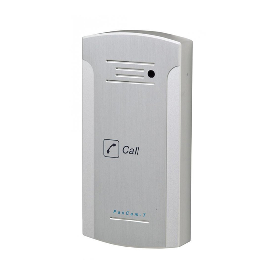
Pantel VoIP outdoor piezo keypad unit The Pancode VoIP and Pantel VoIP are smart wall-mounted and flush-mounted access control door phones connected to a local Voice Over IP (VoIP) network of a VoIP PBX, allowing door entry control. They are available for outdoor installation in an aluminum unit with a piezo keypad. -
Page 5: Pancode Voip/Pantel Voip Kit Contents
Pancode VoIP/Pantel VoIP Access Control Door Phones Installation and Programming Manual Pancode VoIP/Pantel VoIP Kit Contents The contents of the Pancode VoIP/Pantel VoIP are as follows: Pancode VoIP or Pantel VoIP unit External 12V AC power supply for the device with / without analog video camera... -
Page 6: Physical Description
Installation and Programming Manual Physical Description The Pancode VoIP and Pantel VoIP are attached to the wall using a bracket and screws. These units are hardwired and powered by an external 12V AC transformer, included in the package. The Pancode VoIP and Pantel VoIP dimensions are: Height: –... -
Page 7: Pantel Voip Front Panel
Pancode VoIP/Pantel VoIP Access Control Door Phones Installation and Programming Manual Pantel VoIP Front Panel The front panel of the Pantel VoIP unit contains a built-in speaker, a microphone, call button and internal video camera hole (optional) (Figure 2-2). Figure 2-2. Pantel VoIP Front Panel... -
Page 8: Installation
Pancode VoIP/Pantel VoIP Access Control Door Phones Installation and Programming Manual Installation The Pantel VoIP/Pancode VoIP is mounted on the provided installation bracket. This mounting bracket should be installed as shown in Figure 3-1. Figure 3-1. Installation Bracket To install the wall bracket: a. - Page 9 Pancode VoIP/Pantel VoIP Access Control Door Phones Installation and Programming Manual Figure 3-2. Installation Adaptor Depth: 2.5 cm Figure 3-3. Unit Installation After installation, you can now program the Pantel/Pancode VoIP unit.
-
Page 10: Pancode Voip/Pantel Voip Schematic Setup
Pancode VoIP/Pantel VoIP Schematic Setup The Pancode VoIP/Pantel VoIP unit is connected to the VoIP PBX as a SIP extension or via any IP router (Network HUB, Switch etc). The unit powers the door lock, provided it is powered by an external supply and not PoE. The unit includes the internal 2 port’s network switch which allows connecting additional network equipment (PC,... -
Page 11: Installing The Pantel Voip/Pancode Voip
Installation and Programming Manual Installing the Pantel VoIP/Pancode VoIP The Pantel VoIP/Pancode VoIP can be installed as an individual access control or used with adjacent access- control devices, such as card reading devices (see Section 4.2). The provided 12V AC or 12V DC external power supply should not be located further than 10m (30ft) from the unit. - Page 12 Pancode VoIP/Pantel VoIP Access Control Door Phones Installation and Programming Manual Figure 4-1. 12 V AC Power supply and analog video camera connectors scheme Figure 4-2 12 V DC Power supply and IP video camera/ server connectors scheme For the installation of the powered-unlocked-state (12 V AC), use DLR...
- Page 13 This will crimp the wire connection. To Install the Pantel/Pancode VoIP: a. Remove the cover from the Pantel VoIP/Pancode VoIP unit and disconnect the wire connector, found at the base of the internal component. b. Connect the two 12V lead wires from the 12V AC power adapter, one to each of the “~12V” terminals (Figure 4-1).
- Page 14 Pancode VoIP/Pantel VoIP Access Control Door Phones Installation and Programming Manual 1. After power-up or reset, the Pancode/Pantel device starts an initialization process, which can take up to 20 seconds. The initialization completion is indicated by short busy signal. 2. Device can be detected in the LAN by using the MAC address shown on the label and QUERY utility from the installation CD.
- Page 15 Pancode VoIP/Pantel VoIP Access Control Door Phones Installation and Programming Manual 1. “PORT 0 “and “PORT 1 “ RJ-45 Network connectors required the direct (straight) cable connection. 2. “SPK. VOL” potentiometer allows the internal Speaker default volume adjustment.
-
Page 16: Installing The Video Camera (Optional)
Installing the analog Video Camera The Pantel VoIP/Pancode VoIP unit can be installed with an internal or external analog video camera. The video camera 12V DC power is supplied via the 11(+) and 12(-) pins located on the Main PCB Connector (see Figure 4-5). - Page 17 Pancode VoIP/Pantel VoIP Access Control Door Phones Installation and Programming Manual Figure 4-6 BNC female socket connector The analog video stream can be routed directly to a TV Monitor 1. Customer takes the full responsibility on the video camera functionality in case when the third part external video camera will be used with the door units.
- Page 18 Pancode VoIP/Pantel VoIP Access Control Door Phones Installation and Programming Manual Internal Video Camera Video Output Video Camera Power Pancode / Pantel IP BNC-F PCB board R 208 RJ-45 RJ-45 Main Port 1 Port 0 Connector Cross Straight 12 11 - 12 V Cam –...
-
Page 19: Installing The Ip Networking Video Camera
DirectX 9.0 supporting viewer, which enable PC CPU resources to drop. The Pantel VoIP/Pancode VoIP unit can be installed with an internal video camera. The video camera 12V DC power is supplied via the 11 and 12 pins located on the Main PCB Connector (see Figure 4-9 Internal IP Camera connections ). - Page 20 Pancode VoIP/Pantel VoIP Access Control Door Phones Installation and Programming Manual Figure 4-9 Internal IP Camera connections Release all required Pantel / Pancode IP cable’s connections following by the user’s manual: LAN, Power supply and power up the Pantel/Pancode IP unit Install the Video Camera Management software by double click on the ‘MPEG4...
- Page 21 Pancode VoIP/Pantel VoIP Access Control Door Phones Installation and Programming Manual Figure 4-10 IP Utility Windows OS start path • Network Server’ IP Utility’ screen appears Figure 4-11 Network Server searching button • Press on the ‘IP Find ‘ button in order to scan the local network ‘LAN’ for existing installed Pancode / Pantel IP devices with the internal network server.
- Page 22 Pancode VoIP/Pantel VoIP Access Control Door Phones Installation and Programming Manual Figure 4-12 IP Utility Detected device If no any network server detected check the Pancode / Pantel IP Power connection and LAN (Port 0 RJ-45 ) cable connection. •...
- Page 23 Pancode VoIP/Pantel VoIP Access Control Door Phones Installation and Programming Manual • Press ‘IP Change’ button and wait till the Network parameters will be accepted. Appropriate message will be shown on the screen Figure 4-14 Updating network parameters • Press ‘Ping’ button in order to check the LAN connectivity with the Network Server. DOS prompt...
- Page 24 Pancode VoIP/Pantel VoIP Access Control Door Phones Installation and Programming Manual Figure 4-15 Ping Network Server • Close the ‘IP utility’ • Launch the ‘MPEG 4 Communicator’ utility Figure 4-16 MPEG 4 Communicator Windows OS startup • MPEG 4 Communicator utility screen appears •...
- Page 25 Pancode VoIP/Pantel VoIP Access Control Door Phones Installation and Programming Manual Figure 4-17 MPEG4 Communicator utility screen • Configuration table appears Figure 4-18 Add ‘New Server’ to the list • Press ‘New Server’ button. Application adds new server account in the left side of the table.
-
Page 26: Web View
Pancode VoIP/Pantel VoIP Access Control Door Phones Installation and Programming Manual Figure 4-19 Connection with the New network Server • Wait some seconds till the Video stream will be shown on the MPEG 4 application screen Figure 4-20 MPEG 4 Communicator video stream 4.1.3... - Page 27 Pancode VoIP/Pantel VoIP Access Control Door Phones Installation and Programming Manual The default Network Server IP address is 192.168.1.8. Enter the existing Network Server IP address in case if the default IP address was changed The default Administrator’s login is: ID – ‘admin’, Password – ‘admin’. Don’t forget to change the default Administrator’s login information in order to keep security level.
- Page 28 Pancode VoIP/Pantel VoIP Access Control Door Phones Installation and Programming Manual Figure 4-23 Web Access to video stream...
-
Page 29: Adjacent Access Control Device
Installation and Programming Manual Adjacent Access Control Device This section describes adding an access-control device to an existing Pantel VoIP/Pancode VoIP, and adding a Pantel VoIP/Pancode VoIP to an existing access-control device. The key difference between these two installations is which access-control device controls the door lock relay. - Page 30 Pancode VoIP/Pantel VoIP Access Control Door Phones Installation and Programming Manual To add a Pantel VoIP/Pancode VoIP to an access control device: The access control device opens the door when the Pantel/Pancode triggers the access-control device. For this installation, the access-control device “Bypass Switch” (SW) wires are connected to the “N.O.” and “CMN”...
-
Page 31: Programming
Installation and Programming Manual Programming The Pancode VoIP/Pantel VoIP units are programmed through web-based GUI interface. This process can be implemented after the unit has been installed on the wall, since it requires the connection of an Ethernet cable to the local network. Optionally possible to establish connection between PC and Pancode by using the cross- linked Ethernet cable. -
Page 32: Searching For A Device In Lan
Pancode VoIP/Pantel VoIP Access Control Door Phones Installation and Programming Manual Figure 5-2 PC Network parameters for the Gross-linked cable connection Press OK exit from the PC Network settings and enter to the Pancode IP first web-programming Don’t forget to return the Administrator’s PC network settings to the local network required after the first Pancode IP programming session will be finished. - Page 33 Pancode VoIP/Pantel VoIP Access Control Door Phones Installation and Programming Manual Unit location through a query is possible only when the unit MAC address is known. It appears on the label attached to the rear panel of the device. Use Lower Case only for letters which presents in the MAC address To find the unit in the network: a.
-
Page 34: Scanning For A Device In The Network
To find a device in the network: a. Insert the installation CD and copy the scan.exe file from the Software directory to the local hard drive. b. Disconnect the Pancode VoIP/Pantel VoIP from the external power supply. Start MS Windows DOS prompt application. -
Page 35: Application Interface
Pancode VoIP/Pantel VoIP Access Control Door Phones Installation and Programming Manual Application Interface When running the application, the login screen appears: Figure 5-5 Web GUI login screen Type ‘Login’ as User name and ‘Password’ in order to enter to programming screens. - Page 36 Pancode VoIP/Pantel VoIP Access Control Door Phones Installation and Programming Manual Figure 5-6. Application Interface The navigation menu contains the following items: System Authorization parameters Local network parameters Proxy server parameters Codec Type Volume settings Time mode DHCP support Dialing mode...
-
Page 37: System Parameters
Contains the unit authorization on the SIP proxy server. Legal entry: 5 to Account Password (password) 20 characters 0-9, A-Z, a-z. Identifies the Pantel VoIP/Pancode VoIP device on the TCP/IP network. IP Address – Local Address Legal entry: digits 0-9 only. Example: 192.168.21.10. - Page 38 Pancode VoIP/Pantel VoIP Access Control Door Phones Installation and Programming Manual Parameter Description User Domain In most cases it is the same as the Registar Address (Proxy server IP address). In special cases it is required to enter Company Domain IP address.
- Page 39 Speed-dialing – sets the Pancode VoIP to speed-dialing operation mode. In this mode, it is possible to make a call using a two-digit speed dial code (11 to 35) to internal or external subscribers.
-
Page 40: Voip Dialing Settings
Displays the IP Door panel internal hardware edition number. VoIP Dialing settings The VoIP Dialing Parameters screen displays the dialing and door opening definitions. Pancode VoIP has two dialing modes: standard and sped-dial. Pantel VoIP has the standard mode only. The VoIP Dialing screen contains the following areas:... - Page 41 Pancode VoIP/Pantel VoIP Access Control Door Phones Installation and Programming Manual Parameter Description Prefix for direct dialing field – contains the first digit of a target phone Direct Dialing To extension number, to which it is possible to call directly. You can enter up to eight prefix prefixes using a coma separator.
- Page 42 Pancode VoIP/Pantel VoIP Access Control Door Phones Installation and Programming Manual Parameter Description Contains the number of the target phone, which will be dialed if a Call Button Destination destination number dialed by visitor is not answer during specific time Forward no Answer interval.
- Page 43 Pancode VoIP/Pantel VoIP Access Control Door Phones Installation and Programming Manual Parameter Description * - Parameter means for the technical purposes only. DNS IP address * This parameter allows to Network administrator to check the IP connectivity by using the “Ping” command and DNS name as argument instead of using the real destination IP address.
-
Page 44: Firmware/Software Upgrade
Installation and Programming Manual Firmware/Software Upgrade Only a firmware file provided by an authorized ITS Company representative can be used for the IP Door unit software upgrade procedure. The firmware upgrading procedure requires TFTP client software, such as "tftpd32" software. - Page 45 Pancode VoIP/Pantel VoIP Access Control Door Phones Installation and Programming Manual Figure 6-2. Tftpd32 Application Screen h. Wait for beep signal, which indicates that device restart process is complete. This may take a few minutes. Restore the connection session with the IP Door unit.
-
Page 46: Technical Specification
Pancode VoIP/Pantel VoIP Access Control Door Phones Installation and Programming Manual Technical Specification Power supply 12V AC; 1.5A or Power Over Ethernet IEEE 802.3af compliant 12 V DC 3A – for devices with the video over IP option ( Analog camera and internal video web-server) 1. -
Page 47: Analog Video Camera Technical Specification
Pancode VoIP/Pantel VoIP Access Control Door Phones Installation and Programming Manual Analog Video Camera Technical Specification Black and White Video Camera Model number MK-03261C TV System EIA/CCIR Image Sensor Device 1/3” interline transfer CCD Image Sensor Area 4.8mm x 3.6mm Horizontal Frequency 15.625KHz... -
Page 48: Network Server Technical Specification
Pancode VoIP/Pantel VoIP Access Control Door Phones Installation and Programming Manual Network Server Technical Specification Internal Network Server Model S-3838 Video Channel Compression MPEG4 / JPEG Resolution (Max.) 720X480(NTSC) 720X576(PAL) Frame Rate (Max.) 30fps(NTSC) , 25fps(PAL) Viewer programs Web view; MPEG 4 viewer;...
Need help?
Do you have a question about the Pancode VoIP and is the answer not in the manual?
Questions and answers