
Subscribe to Our Youtube Channel
Related Manuals for ETC microVision FX


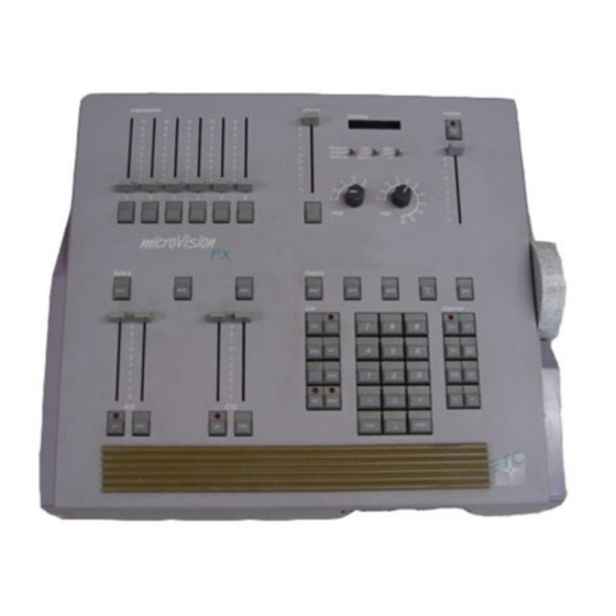
Summary of Contents for ETC microVision FX
-
Page 1: User Manual
Lighting control system Version 1.33 User Manual Copyright 1991-95 Electronic Theatre Controls 4080M1002 Revised June 1995... -
Page 2: Limited Warranty
Limited warranty Electronic Theatre Controls (ETC) warrants to the original owner or retail The owner’s obligations during the customer that for a period of one year warranty period under this warranty are from date of delivery of a portable to notify ETC at ETC’s address within... -
Page 3: Table Of Contents
Customer service ................1 - 6 Chapter 2 Installation ....................2 - 1 MicroVision FX back panel ..............2 - 2 Installing your console and monitor ............ 2 - 3 Installing two monitors ..............2 - 4 Monitor connectors and pinouts ..........2 - 5 Connecting dimmers ................ - Page 4 MicroVision FX Chapter 3 Entering softpatch and system settings ..................3 - 1 Entering softpatch ................3 - 2 Entering numbers of channels and dimmers ........ 3 - 3 Entering one-to-one softpatch ............3 - 4 Creating custom softpatch ............3 - 5 Using channel zero ..............
- Page 5 Table of Contents Lesson 3: Playing back cues ............. 4 - 24 Selecting cues ................4 - 25 Timed fader pairs ............... 4 - 26 Playing back cues ............... 4 - 26 Go to a different cue ..............4 - 27 Controlling fades manually ............
- Page 6 MicroVision FX Chapter 5 Using print and disk options ..........5 - 1 Print functions ..................5 - 2 Bold printing ................. 5 - 3 Cue sheet ..................5 - 4 Cues ..................... 5 - 5 Patch .................... 5 - 6 Real time programs ..............
- Page 7 Table of Contents Chapter 7 Reference ....................... 7 - 1 And ..................... 7 - 2 At ......................7 - 3 Back ....................7 - 4 Black out ..................... 7 - 5 Blind ....................7 - 6 Bump switches ................... 7 - 7 Captured channels ................
- Page 8 MicroVision FX Thru ....................7 - 48 Timed fader pairs ................7 - 49 Track ....................7 - 50 Appendix A Error messages ..................A - 1 Appendix B Specifications ..................B - 1 Interfaces ................B - 1 Cue capacity ................
-
Page 9: Chapter1 Introduction
MicroVision FX allows you to create a wide range of dramatic, on-stage effects using up-to-the-minute theatrical lighting technology. This chapter includes information to orient you to the console and the manual. It includes the following sections: MicroVision FX features •... -
Page 10: Microvision Fx Features
1 - 2 MicroVision FX MicroVision FX features MicroVision FX provides the following features: • Six manual faders that control programmed submasters • Five pages of submasters memories • 125 control channels • Proportional softpatch that accommodates up to 512 dimmers •... -
Page 11: Using This Manual
Chapter 1 Introduction 1 - 3 Using this manual This manual provides instructions for MicroVision FX ’s features and optional accessories. The following chapters are included: Chapter 1 MicroVision FX capabilities, console and manual Introduction conventions, getting help, and customer support. -
Page 12: Text Conventions
Pile-on convention MicroVision FX uses a pile-on convention rather than last-action conven- tion to determine levels for channels. Pile-on means that MicroVision FX reads all output levels it receives for a specific channel and sets that channel to the highest of these levels. For example, a channel included in a submaster and a cue will output at the higher of the two levels. -
Page 13: Getting Help
Chapter 1 Introduction 1 - 5 Getting help Help screens are available for all MicroVision FX keys. To display help screens: 1. Press [Help]. 2. Press any key on the console. MicroVision FX displays a description of the key you pressed. Help screens are not available for menu... -
Page 14: Customer Service
Monday through Friday, from 9:00 AM to 5:00 PM Central Standard Time. After hours and weekend calls are answered electronically and forwarded to a service representative. Address all correspondence about the MicroVision FX to: Electronic Theatre Controls, Inc. Customer Service Department... -
Page 15: Chapter 2 Installation
This chapter includes set up instructions that you need to perform when you install MicroVision FX and any optional accessories. Chapter 3, Entering softpatch and system settings includes instructions for entering the software settings that you will probably update before you begin a new show. -
Page 16: Microvision Fx Back Panel
2 - 2 MicroVision FX MicroVision FX back panel MIDI Printer Serial Port CRT DISPLAY monochrome Analog Interface Power in PUSH Remote Remote go Audio 1-96 97-192... -
Page 17: Installing Your Console And Monitor
Chapter 2 Installation 2 - 3 Installing your console and monitor This section includes installation instructions for MicroVision FX , and connector and pinout specifications for the monitor. Follow these steps to install your MicroVision FX : 1. Place console on a hard, stable, flat surface with at least six inches of space behind it for ventilation and cable clearance. -
Page 18: Installing Two Monitors
MicroVision FX 8. Turn console and monitor power switches to their On positions. 9. Press [Setup]. 10. Select 7, System settings, press [Enter]. MicroVision FX displays System Settings Menu. 11. Select 9, Color/monochrome monitor, press [Enter]. MicroVision FX displays Color/Monochrome Monitor selection menu. -
Page 19: Monitor Connectors And Pinouts
Chapter 2 Installation 2 - 5 Monitor connectors and pinouts RGB color or TTL monochrome Console connector DB-9 male Pinout Common (AC ground) Common (AC ground) Green Blue Intensity (green) Monochrome video HSync VSync(60Hz) Composite monochrome (coaxial cable) Console connector BNC female Pinout Center Video (60Hz) -
Page 20: Connecting Dimmers
3. Verify that options 6, 7 and 8 indicate the proper dimmer settings for your system. Standard digital output protocols DMX512 and D192 protocols are standard on MicroVision FX . To select the correct protocol, select 6, Digital protocol, and press [Enter]. Enter 1 to select DMX512, or 2 to select D192. -
Page 21: Digital Outputs (Dmx512 And D192)
Clock (+) Analog data Clock (-) Note: You can configure MicroVision FX for Strand CD80 Dimmer I and Dimmer II cabling convention (maximum 192 ouitputs). Contact an authorized dealer or ETC if you need more information on connecting to CD80 racks. -
Page 22: Analog Wire-Per-Dimmer Input (Optional)
2 - 8 MicroVision FX Analog wire-per-dimmer input (optional)* Connector Centronics D-36 male Pinout Connector one Pins 1-32 = dimmers 1-32 Connector two Pins 1-32 = dimmers 33-64 Connector three Pins 1-32 = dimmers 65-96 All connectors Pins 33-36 = common (Earth ground) -
Page 23: Installing Printer
Chapter 2 Installation 2 - 9 Installing printer MicroVision FX supports parallel printers. Serial printers are not sup- ported. Printer functions are described in Chapter 5, Using print and disk options . Pinout and connector specifications are on the next page. -
Page 24: Installing Infrared Remote Focus Unit (Irfu)
IRFU connector on the back panel. Power is supplied by the console. MicroVision FX also allows you to use the IRFU configured as a wireless remote in some circumstances and a wired remote in others. To do this, connect the receiver to the IRFU connector on the console's back panel. - Page 25 Chapter 2 Installation 2 - 11 To install the IRFU on a properly configured MicroVision FX console, follow these steps: 1. Verify that the receiver unit is properly connected to the console and that battery in transmitter is good. 2. Press [Set Up].
-
Page 26: Irfu Receiver Unit To Console Connector And Pinout
2 - 12 MicroVision FX IRFU receiver unit to console connector and pinout Receiver connector Console connector DIN 3-pin female DIN 5-pin female Signal Ground PPM data +12V Not used Not used IRFU transmitter to console connector and pinout Transmitter connector... -
Page 27: Installing Remote Go
Chapter 2 Installation 2 - 13 Installing Remote Go A MicroVision FX console configured for an optional Remote Go provides a 25-pin connector on the back panel. The remote unit connects to the MicroVision FX console via a 24 AWG, aluminum-shielded, multi-conduc- tor cable with one twisted pair designated for each switch (Belden 9507 S-R PCV Insulated or Alpha 5477 80 Deg. -
Page 28: Installing Audio Input
2. Check to be sure that the opposite end is properly terminated to the audio source. 3. Verify that power is on for both the MicroVision FX and the audio source. 4. Start the chase running. -
Page 29: Entering Softpatch And System Settings
Chapter 3 Entering softpatch 3 - 1 chapter 3 entering softpatch and system settings Before you begin creating cues for a show you should first create your softpatch. The softpatch assigns individual dimmers to control channel numbers. You can use a default one-to-one softpatch setup, or you can assign groups of dimmers to channels. -
Page 30: Entering Softpatch
3 - 2 MicroVision FX Entering softpatch MicroVision FX accommodates up to 512 dimmers on 125 channels. Softpatch gives you complete flexibility in assigning dimmers to control channels. Softpatch also allows you to proportionally patch individual dimmers to channels to balance a wash or ensure that a specific lamp cannot be brought above a specific level. -
Page 31: Entering Numbers Of Channels And Dimmers
Chapter 3 Entering softpatch 3 - 3 Entering numbers of channels and dimmers Follow these steps to set the number of dimmers and channels in your system: 1. Press [Set Up]. 2. Select 7, System settings, and press [Enter]. 3. Select 1, Number of dimmers, and press [Enter]. 4. -
Page 32: Entering One-To-One Softpatch
To use MicroVision FX ’s default softpatch setting follow these steps: 1. Press [Set Up]. 2. Select 7, System settings, and press [Enter]. -
Page 33: Creating Custom Softpatch
Chapter 3 Entering softpatch 3 - 5 Creating custom softpatch The following sections include information about creating a custom softpatch. • Using channel zero • Patching dimmers to channels Hint: If you use the same softpatch for several shows, create the softpatch, and record it on a disk before you record any cues. -
Page 34: Patching Dimmers To Channels
Each dimmer can only be patched into one channel at a time. Follow the steps below to create a custom softpatch. 1. Press [Patch]. MicroVision FX displays the following screen. 2. Select dimmers to assign to a single channel. To select a single dimmer: a) Enter the dimmer number. - Page 35 Chapter 3 Entering softpatch 3 - 7 Shortcut: Combine [And] and [Thru] commands to select any combi- nation of dimmers. For example, press [1] [Thru] [5] [And] [1][0] [Thru] [2][0] to select 1 through 5 and 10 through 20. 3. Enter the channel number to which you want to assign selected dimmers;...
-
Page 36: Additional Patching Features
Softpatching to Strand CD80 dimmer rack Proportional patching MicroVision FX lets you assign proportional levels to individual dimmers from the softpatch screen. You may want to inhibit an individual dimmer to balance the wash in a channel or to limit a particular lamp. Dimmers default to a full level setting unless you inhibit them. -
Page 37: Capturing Channels In Softpatch
3 - 9 Capturing channels in softpatch MicroVision FX lets you select and capture channels without returning to Stage mode so you can bring channels up on stage for a dimmer check or to view the proportional settings of dimmers assigned to a channel while you set them. -
Page 38: Unpatching Individual Dimmers
MicroVision FX Unpatching individual dimmers MicroVision FX allows you to select a single dimmer and bring it up independent of other dimmers softpatched to the same channel. This is called unpatching a dimmer. If a channel has more than one dimmer softpatched to it, you may want to unpatch a single dimmer to check an individual fixture, to turn on a work light, or to focus a single dimmer. -
Page 39: Softpatching To A Strand Cd80 Dimmer Rack
Chapter 3 Entering softpatch 3 - 11 Softpatching to a Strand CD80 dimmer rack Strand CD80 dimmer racks have 48 dimmer slots that accept AMX192 protocol. Each dimmer slot holds either two 2.4 kw dimmers or one 6 kw or 12 kw dimmer. When configuring a softpatch using a Strand CD80 rack, all 96 possible dimmer numbers per rack must be included. -
Page 40: Entering System Settings
3 - 12 MicroVision FX Entering system settings These system settings are discussed on the following pages: • Default full level • Default up and down fade times To display the System Settings Menu, follow these steps: 1. Press [Set Up]. -
Page 41: Setting Default Full Level
3 - 13 Setting default full level The default full setting is the level MicroVision FX enters for selected channels when you press [Full]. The default setting for full is 100 per- cent, and is reset to 100 percent after a diagnostic system clear. -
Page 42: Setting Default Up And Down Fade Times
MicroVision FX Setting default up and down fade times When you record cues, MicroVision FX automatically enters default up and down fade times unless you specify different fade times. The default fade time is five seconds. To customize default fade times, follow these steps: 1. -
Page 43: Chapter 4 Tutorial
4 tutorial This chapter includes lessons on working with MicroVision FX ’s basic features: cues, submasters and chases. Each lesson is described briefly below. • Lesson 1 describes display and channel modes and record functions. • Lesson 2 includes instructions for creating several cues. -
Page 44: Lesson 1 Display, Channel And Operation Modes
This lesson describes display and channel modes and record functions available in MicroVision FX . Display modes show channel and level settings for cues, submasters and fader pairs. Channel modes indicate how channels respond when they are in different situations. -
Page 45: Stage And Blind Screens
Chapter 4 Tutorial 4 - 3 Stage and Blind screens Stage and Blind screens look very similar. The Stage mode screen is illustrated below. Display mode screen description Grand Master setting The Grand Master setting displays the master intensity level. With it you can proportionally inhibit the level of all channels. - Page 46 MicroVision FX indicates that a submaster is recorded in a page other than the currently loaded page by displaying and highlighting that page number under the submaster number.
-
Page 47: Channel Modes
Captured channels override all other channel settings. For example, if a channel is in a fader at 100 percent and you capture it and set it to 50 percent, MicroVision FX reads the 50 percent setting from the captured channel. -
Page 48: Recorded Channels
4 - 6 MicroVision Recorded channels Recorded channels are channel levels that have been recorded in a cue or submaster. In Stage mode, recorded levels appear on the screen when they are in a fader pair or in an active submaster. On a color monitor in Stage mode, recorded levels are displayed in white. -
Page 49: Record Functions
4 - 7 Record functions MicroVision FX has two record functions: Record and Track. Record saves all channels as they appear on the screen (what you see is what you get) in the cue or submaster you specify. When you use Record to record a cue, levels are recorded in only the cue you specify. -
Page 50: Lesson 2: Working With Cues
After you select channels and set their intensity, you can store the look as a cue. You can save up to 200 cues per show in MicroVision FX . When you record a cue, MicroVision FX displays a message telling you how many cues are still available. -
Page 51: Creating Cues
Viewing cues There are several methods you can use to create any one look with MicroVision FX . Deciding how to create a look depends on your situation and what information is already stored in the console. If you already have several cues recorded, you may want to use the look from one cue and add to it to create another. -
Page 52: Cue 1: Creating A Cue In Stage
Once you are in Stage, you have live control of channels. Follow these steps to create a cue in Stage mode: 1. Press [Stage]. MicroVision FX displays the Stage mode screen and automatically prompts you to enter a channel number. - Page 53 Chapter 4 Tutorial 4 - 11 Cue 1 keystrokes: Action [Stage] Displays Stage mode. Selects channel 1. [At] Indicates next number entered will be an intensity level. [7][5] Enters intensity level of 75 percent. [Record] Indicates that you want to record cue. Enters cue number.
-
Page 54: Cue 2: Creating A Cue In Blind
[Full]. MicroVision FX automatically enters 00 for channels you used in cue 1 to indicate that they will fade out in cue 2. 1. Press [Blind]. MicroVision FX displays Blind mode screen. You do not have live control of channels in Blind. MicroVision FX automati- cally prompts you to enter cue number. - Page 55 Chapter 4 Tutorial 4 - 13 Cue 2 keystrokes: Action [Blind] Displays Blind mode screen. Selects cue 2. [Chan] Indicates that the next number entered will be a channel. Selects channel 1. [Thru] Indicates you are going to enter a range. [1][5] Marks end of range.
-
Page 56: Cue 3: Creating A Cue With Modified Fade Times
MicroVision Cue 3: Creating a cue with modified fade times When you create a cue, MicroVision FX assigns default fade times to the cue. If you prefer, you can modify the fade times using [Time]. Note: Default fade time is factory set at five seconds. For information on changing default fade times, see page 3 - 14. - Page 57 Chapter 4 Tutorial 4 - 15 Cue 3 keystrokes: Action [Chan] Indicates next number entered will be a channel. [2][6] Marks beginning of range. [Thru] Indicates that you are entering a range. [5][0] Marks end of range. [Full] Enters full intensity for selected channels. [Time] Indicates that you want to change fade times.
-
Page 58: Cue 4: Creating Linked Cues
4 - 16 MicroVision Cue 4: Creating linked cues MicroVision FX lets you link cues to create a sequence that runs auto- matically. You can link a string of cues, or you can create a loop to produce a chase. - Page 59 Chapter 4 Tutorial 4 - 17 Cue 4 keystrokes: Action [Blind] Displays Blind mode screen. [Chan] Indicates that your are going to enter channel numbers. [5][1] Selects channel 51. [Thru] Indicates that you want to enter a range of channels. [7][5] Marks end of range of channels.
-
Page 60: Cue 5: Creating A Cue Using Rem Dim
4. Enter another channel number with numeric keypad to mark the end of the range. 5. Press [Rem Dim]. MicroVision FX sets all unselected channels to a level of zero. 6. Move the fader wheel, press [At], [+] and [-], or use [At] and numeric keypad to set desired level. - Page 61 Chapter 4 Tutorial 4 - 19 Cue 5 keystrokes: Action [Chan] Indicates that the next number entered will be a channel number. [6][0] Marks the beginning of the subset. [Thru] Indicates you are selecting a range of consecutive channels. [6][5] Marks the end of the range.
-
Page 62: Inserting Cues
(1.1, 1.2, etc.). To modify and insert a cue, follow these steps: 1. Press [Blind]. MicroVision FX automatically prompts you for a cue number. 2. Enter cue number you want to modify. -
Page 63: Copying Cues
Chapter 4 Tutorial 4 - 21 Copying cues Once you have created a cue, you may copy it and give it a new number. This can be helpful if you want to create a cue based on one you have already recorded. -
Page 64: Deleting Cues
Warning: When you initiate Clear system, all show data stored in MicroVision FX is lost; system settings are not affected. Save the current show on disk if you do not want to permanently lose all show... -
Page 65: Viewing Cues
Chapter 4 Tutorial 4 - 23 Viewing cues Once you have created a few cues, you may want to look at them. You can view stored cues in two ways, live in Stage mode, or on the screen in Blind mode. To view cues live, you must select the cue and play it back in a fader;... -
Page 66: Lesson 3: Playing Back Cues
Lesson 3: Playing back cues Now that you have some cues, you’re probably anxious to play them back. MicroVision FX has two sets of timed fader pairs that playback recorded cues. The left fader in each pair (faders A and C) controls upfades. -
Page 67: Selecting Cues
Selecting cues There are three ways a cue can be selected to playback on stage: 1) when a cue is playing, MicroVision FX automatically selects the next cue; 2) you select cue manually; or 3) MicroVision FX automatically selects linked cues. You must be in Stage mode to select cues to playback. -
Page 68: Timed Fader Pairs
4 - 26 MicroVision Timed fader pairs When fader controls are set at 10, MicroVision FX plays fade times as you recorded them. For information on taking manual control of fades, see the section titled Controlling fades manually later in this lesson. -
Page 69: Go To A Different Cue
Chapter 4 Tutorial 4 - 27 Go to a different cue To play back a cue other than the selected (highlighted) cue on the cue sheet, follow these steps: 1. Press [Cue]. 2. Enter the cue number you want to play next. 3. -
Page 70: Controlling Fades Manually
When you begin a linked cue with the right fader at 10, MicroVision FX plays it back at the recorded rate. To take control of the playback rate, move the fader to 50 percent. -
Page 71: Modifying Cues On Stage
Chapter 4 Tutorial 4 - 29 Modifying cues on stage To modify and record a cue on stage, follow these steps: 1. Press [Stage]. 2. Press [Cue], and enter cue number. 3. Press [Go] to playback cue. 4. Push faders down and back up to override fade times. 5. -
Page 72: Back Key
4 - 30 MicroVision Back key After you play a cue, pressing the Back key plays back the cue that precedes it on the cue sheet. For example, assume you have recorded cues one, two and three. If you play cue one and then cue two, pressing [Back] brings up cue one again. But, if you play cue one and then cue three, pressing [Back] will bring up cue two because it immediately precedes cue three on the cue sheet. -
Page 73: Lesson 4: Working With Submasters
See page 4 - 37 for information about using submasters to create chases. MicroVision FX is equipped with six submaster potentiometers, or pots . You can record a submaster memory in each pot. The pot allows you to bring up the submaster look manually. -
Page 74: Submaster Pages
4 - 32 MicroVision Submaster pages MicroVision FX has five pages of submasters. You can record six sub- masters in each page. In Stage mode, the Submaster/cue window indicates which submasters are recorded in the currently loaded page. It also indicates if active submasters originated from a different page. -
Page 75: Recording A Submaster
Chapter 4 Tutorial 4 - 33 Recording a submaster Creating a submaster is as easy as creating a cue. You can create submasters in Stage or Blind mode. To create a submaster, follow these steps: 1. Select channel and level settings as you did for cues. See Lesson 2, Creating cues if you need a review. -
Page 76: Recording Submaster On A Different Page
4 - 34 MicroVision Recording submaster on a different page You may record a submaster to a page other than the one currently loaded. For example, if you have page one loaded, you can create a look on stage, and record it to page two if you wish. To do so, follow these steps: 1. -
Page 77: Copying Submasters
Chapter 4 Tutorial 4 - 35 Copying submasters You may want to copy a submaster, or use submasters as building blocks for new submasters. To copy a look from one submaster to another in Stage, follow these steps: 1. Press [Stage]. 2. -
Page 78: Deleting Submasters
Or, press [Clear] to cancel the operation. Warning: When you initiate Clear system, all show data stored in MicroVision FX is lost; system settings are not affected. Save the current show on disk if you do not want to permanently lose all show... -
Page 79: Lesson 5: Creating And Working With Chases
The chase continues to run, but with new submasters in place of the old ones. MicroVision FX allows you to determine the number of submasters you include in a chase (up to six), and also to control the chase speed and output levels of the submasters. -
Page 80: Creating A Chase
4 - 38 MicroVision Creating a chase Each chase step consists of a channel or group of channels recorded as a submaster. The first step in creating a chase is to record the submas- ters that you want to include in it. Note: You can create submasters in either Stage or Blind mode. - Page 81 If you want to use a music source to control the chase rate through your MicroVision FX's audio input connector, set the switch to Audio. MicroVision FX analyzes the tempo of the music and sets the chase rate accordingly. (See page 4 - 42 for more information.)
-
Page 82: Setting Chase Output Levels
4 - 40 MicroVision Setting chase output levels When you record the submasters included in a chase, you assign an output level to the channels that make up the submaster. After you record the submasters, you can modify their output level by setting the level of the potentiometer labeled Effects. -
Page 83: Setting Number Of Submasters In A Chase
Chapter 4 Tutorial 4 - 41 Setting number of submasters in a chase The rotary pot labeled Step allows you to select the number of submas- ters you want to include in a chase. This can be handy if you want to create a chase that does not require all six submasters, or if you need to reserve some submasters for other purposes. -
Page 84: Controlling Chases With Audio Input
MicroVision Controlling chases with audio input The Audio setting on MicroVision FX 's Rate pot allows you to use input from an audio source (tape, CD, LP, or live music) to control chase rate. The processor detects notes in certain low frequencies (usually the bass drum part) and uses them to set the chase rate. -
Page 85: Lesson 6: Saving Your Show On Disk
Chapter 4 Tutorial 4 - 43 Lesson 6 Saving your show on disk You should always make at least one back up copy of each show you are working on. Back up copies are stored on standard 3.5-inch computer disks. We suggest that you make back up copies of your work after every session during which you modify a show. -
Page 86: Formatting Disks
4 - 44 MicroVision Formatting disks You must format disks on a MicroVision FX console before you can record shows on them. MicroVision FX cannot record shows on unformatted disks or disks that are formatted on other types of ETC consoles or personal computers. -
Page 87: Recording A Show On Disk
Recorded, or the date recorded if you have the Real Time Clock option. If no show is recorded on disk, MicroVision FX displays the message, Not recorded. 4. Select a show number (1 through 5), and press [Enter]. If the show number you select is already recorded, the new show will overwrite the old show. -
Page 88: Reading A Show From Disk
2. Press [Set Up]. 3. Select 2, Read show from disk, and press [Enter]. MicroVision FX displays the message Not recorded for shows that are not yet recorded on the disk. 4. Select the desired show and press [Enter]. The show you enter will overwrite the current show in memory. -
Page 89: Lesson 7: Track Record Function
4 - 47 Lesson 7 Track record function The Track record function helps you use MicroVision FX more efficiently and create more complex lighting effects. Track is a record function that allows you to modify recorded cues and designate new levels for the displayed cue only or to track them forward until a different level is encountered. -
Page 90: Using Record To Create Tracks
4 - 48 MicroVision Using record to create tracks In Stage mode, the following keystrokes create the five cues illustrated below. Each cue adds channels to the previous cue. The example uses Record to record the cues. Cue 1 [Chan] [1] [Full] [Record] [1] [Enter] Cue 2 [Chan] [2] [Full] [Record] [2] [Enter] Cue 3 [Chan] [3] [Full] [Record] [3] [Enter] Cue 4 [Chan] [1] [At] [2][5] [4] [Full] [Record] [4] [Enter]... -
Page 91: Recording Modified Cues
Chapter 4 Tutorial 4 - 49 Recording modified cues The difference between Record and Track is apparent when you modify a cue or insert a new cue between two existing cues. Record and Track produce different results. The following keys were pressed to release captured channels and play back cue 1. - Page 92 4 - 50 MicroVision To track the level modification we just recorded in the example above use [Track] instead of [Record] to record channel one as on the previous page. Press [Track], enter cue number, and press [Enter]. If you use [Track] rather than [Record] to record the changes made to the cue illustrated in Figure 1, the results will be as illustrated in Figure 3 (versus the results from using [Record] illustrated in Figure 2).
-
Page 93: Inserting Cues
Channel 5 Figure 4. Note that MicroVision FX enters a level of 00 percent for channel 4 in cue 2. This downfades the channel when cue 2 is played. When you insert a cue with [Track] new channels track through the cues after it until MicroVision FX encounters a cue with a level previously recorded for that channel. - Page 94 4 - 52 MicroVision Pressing [Track] (rather than [Record] as in the previous example) then [1][.][1] [Enter] to insert and record the same cue 1.1 as above produces the results illustrated in Figure 5. Compare it to the results illustrated in Figure 4, in which the same cue was inserted using [Record] rather than [Track].
-
Page 95: Blackout Cues And Tracking
Chapter 4 Tutorial 4 - 53 Blackout cues and tracking Sometimes you may add a channel to a sequence of cues that has not used that channel yet. For example, you may want to add a channel to all cues in a scene. To do this, add the channel to the first cue in the sequence, and use Track to track the change through the remaining cues. - Page 96 4 - 54 MicroVision If cue 5 is a blackout cue, MicroVision FX records all unused channels in Cue 5 at 00 percent. In the example below, the blackout automatically enters 00 in channel 5, cue 5. When you track a channel through the sequence, the new channel will not track through the blackout cue.
-
Page 97: Using Print And Disk Options
• Submasters MicroVision FX is equipped with a 3.5-inch disk drive on the right front side panel of the console. It allows you to save backup copies of shows on disk. Disk options and disk management are discussed in the section titled Disk management on page 5 - 10. -
Page 98: Print Functions
To print a report: 1. Enter menu option number and press [Enter]. 2. Follow prompts that ask for beginning and ending numbers, if any. 3. Press [Enter]. MicroVision FX sends reports to the printer. To cancel the print operation, select 8, Abort print. -
Page 99: Bold Printing
Chapter 5 Using print and disk options 5 - 3 Bold printing The Bold printing option on the Print Functions Menu enables the Print cues option to print moving channels in bold as moving channels are displayed highlighted in Blind mode. To enable bold printing, follow these steps: 1. -
Page 100: Cue Sheet
[Enter] if you want to print the entire cue sheet. Press [Enter]. If you are selecting a range of cues to print, MicroVision FX prompts you for the last cue number to print. Enter the last cue number you want, and press [Enter]. -
Page 101: Cues
[Enter] to print all recorded cues. If you are selecting a range of cues to print, MicroVision FX prompts you for the last cue number to print. Enter the last cue number you want, and press [Enter]. -
Page 102: Patch
Patch The softpatch report lists current dimmer-to-channel patches. When you select the Patch option MicroVision FX sends the report to the printer immediately. No options are available for this report. From the Print Functions menu, select 3, and press [Enter]. -
Page 103: Real Time Programs
5 - 7 Real time programs From the Print Functions menu, select 6, and press [Enter]. MicroVision FX prints a report of all recorded real time programs on one sheet. To interupt the print operation, press [8], Print functions, then [8], Abort print. -
Page 104: Stage Display
Stage display The Stage display report prints channel settings as they currently appear on stage. When you select Print stage display, MicroVision FX sends the report to the printer immediately. No options are available for this report. From the Print Functions Menu, select 4, and press [Enter] To interupt the print operation, press [8], Print functions, then [8], Abort print.. -
Page 105: Submasters
[Enter] if you want to print all recorded submasters. If you are selecting a range of submasters to print, MicroVision FX prompts you for the last submaster page number you want. Enter the last page number, and press [Enter]. MicroVision FX sends the report to the printer. -
Page 106: Disk Management
MicroVision FX clears fader pairs when you read a show from disk into the console. Before you can use a disk in MicroVision FX , you must format it on the console. Formatting instructions are on page 5 - 12. -
Page 107: Storing Disks
Chapter 5 Using print and disk options 5 - 11 Storing disks Computer disks are somewhat fragile, magnetic devices for storing your work. Therefore, we suggest the following disk storage and handling practices to ensure that your work is not lost as a result of disk damage. •... -
Page 108: Formatting Disks
MicroVision FX Formatting disks Before you can use a disk in an MicroVision FX , you must format it on a MicroVision FX console. Disks formatted on other ETC consoles or on a standard personal computer do not work in MicroVision FX . To format a disk, follow these steps: Warning: Formatting a disk erases all information recorded on it. -
Page 109: Recording A Show On Disk
If any shows are currently recorded on disk, the screen displays the message, Recorded, or the date recorded if you have a Real Time Clock. If no shows are recorded on disk, MicroVision FX displays the message, Not recorded. 4. Select desired show (one through five) and press [Enter]. If the show number you select is already recorded, the new show will overwrite the old show. -
Page 110: Reading A Show From Disk
2. Press [Set Up]. 3. Select 2, Read show from disk, and press [Enter]. MicroVision FX displays the message, Not recorded, for shows that are not yet recorded on the disk. 4. Select desired show, and press [Enter]. The show you enter will overwrite the current show in memory. -
Page 111: Chapter 6 Accessories
6 accessories This chapter includes instructions for working with the following MicroVision FX optional accessories: • Infrared Remote Focus Unit (IRFU) • Real Time Clock • MIDI (Musical Instrument Digital Interface) • Remote Go • Analog inputs • Analog outputs •... -
Page 112: Infrared Remote Focus Unit (Irfu)
Infrared Remote Focus Unit (IRFU) The Infrared Remote Focus Unit (IRFU) allows you to control the MicroVision FX console from distances up to 225 feet (75 yards). With it you can playback cues and macros, and access dimmers, channels, groups, and cues. The IRFU can also be wired to the main control console.To enable the IRFU in MicroVision FX , ETC must modify the... - Page 113 Chapter 6 Accessories 6 - 3 Pressing any key on the infrared controller automatically turns power on. Once you have turned the unit on, if no key is pressed after three minutes, the power shuts off. Note: When not connected to the console, the transmitter is powered by a nine-volt, size PP3 battery.
-
Page 114: Real Time Clock
The Real Time Clock also displays the current time under the display mode label and date-stamps shows when you record them on disk. You can record up to 10 real time programs in MicroVision FX . This section includes instructions for creating real time programs and setting the real time clock. -
Page 115: Setting Real Time Clock
Follow these steps to set Real Time Clock: 1. Press [Set Up]. 2. Select 9, Options, and press [Enter]. MicroVision FX displays the following screen: 3. Select 5, Real time clock, and press [Enter]. MicroVision FX displays the following screen:... - Page 116 6 - 6 MicroVision FX 4. Select 2, Set real time clock, and press [Enter]. MicroVision FX displays the following screen: 5. At Time prompt, enter current time in military format. For example, enter 8:00 a.m. as 08:00 and 5:15 p.m. as 17:15. Press [Enter].
- Page 117 Chapter 6 Accessories 6 - 7 8. At Weekday prompt, enter one of the following codes to indicate the current day of the week, then press [Enter]. 1 - Sunday 5 - Thursday 2 - Monday 6 - Friday 3 - Tuesday 7 - Saturday 4 - Wednesday 9.
-
Page 118: Creating Or Editing Real Time Programs
MicroVision FX Creating or editing real time programs 1. Press [Set Up]. 2. Select 9, Options, and press [Enter]. MicroVision FX displays the following screen. 3. Select 5, Real time clock, and press [Enter]. MicroVision FX displays the following screen. - Page 119 6 - 9 4. Select 1, Edit real time programs, and press [Enter]. MicroVision FX displays the following screen. 5. Enter a program number (1 through 10), and press [Enter]. 6. Enter the cue number you want real time program to play. Press [Enter].
- Page 120 6 - 10 MicroVision FX 9. At the days of the week prompt, enter one or more of the following codes to indicate on which days the cue should run. To run a cue on more than one day of the week, use [And] and [Thru] to select a group of days.
-
Page 121: Enabling/Disabling Real Time Programs
Follow these steps to enable or disable real time programs you have recorded: 1. Press [Set Up]. 2. Select 9, Options, and press [Enter]. MicroVision FX displays the following screen. 3. Select 5, Real time clock, and press [Enter]. MicroVision FX displays the following screen. - Page 122 6 - 12 MicroVision FX 4. Select 3, Enable/disable real time programs. MicroVision FX displays the following screen. 5. Enter 1 to enable real time programs, or 2 to disable real time programs, then press [Enter] to record your choice.
-
Page 123: Deleting Real Time Programs
Follow these steps to delete real time programs: 1. Press [Set Up] to display the Set Up Menu. 2. Select 9, Options, and press [Enter]. MicroVision FX displays the following screen. 3. Select 5, Real time clock, and press [Enter]. MicroVision FX displays the following screen. - Page 124 6 - 14 MicroVision FX 4. Select 1, Edit real time programs, and press [Enter]. MicroVision FX displays the following screen. 5. Enter a program number (1 through 10), and press [Enter]. 6. Press [Clear] to delete the program. 7. Press [Set Up] to return to the Setup Menu.
-
Page 125: Midi
MIDI MicroVision FX supports MIDI (Musical Instrument Digital Interface) . To enable MIDI in MicroVision FX , ETC must modify the hardware at the factory . Consoles configured with MIDI option will display a message indicating so during system boot. -
Page 126: Interfacing With Midi
6 - 16 MicroVision FX Interfacing with MIDI Follow these steps to connect MIDI equipment to MicroVision FX : 1. Turn console power off. 2. Insert standard MIDI cable into the connector on the back of the console labeled MIDI In . -
Page 127: Message Formats
Chapter 6 Accessories 6 - 17 Message formats The following table lists MIDI message formats used to control MicroVision FX. All numbers are in Hex format. Note off message format <8n><kk><vv> Note off status MIDI channel number (0-F) Key number (0-7F) -
Page 128: Message Definitions
6 - 18 MicroVision FX Message definitions Submaster bump switch execution Note MIDI # Submaster # Note: C0 = MIDI note #0. C5 = MIDI note #60 or middle C. Cue execution in AB fader pair Next cue Program change 0... -
Page 129: Remote Go
Chapter 6 Accessories 6 - 19 Remote Go Remote Go enables you to control up to seven MicroVision FX functions from a remote location. ETC provides the internal circuitry and the back panel connector for Remote Go. You must provide the remote control unit itself, as well as appropriate cable and connectors. -
Page 130: Analog Inputs
Analog inputs Analog inputs are analog control signals that originate from external sources. MicroVision FX accepts input from 32, 64 or 96 analog inputs, depending on your console's configuration. Analog inputs enable you to incorporate output from analog sources into your console. -
Page 131: Analog Outputs
Analog outputs Analog outputs are analog control signals that originate from the MicroVision FX console. MicroVision FX provides 32, 64 or 96 analog outputs depending on your console’s configuration. Analog outputs work in conjunction with any other output protocol on your console. -
Page 132: Amx192 Outputs
AMX192 outputs AMX192 outputs are analog multiplex control signals that originate from the MicroVision FX console. MicroVision FX provides 96 or 192 AMX192 outputs depending on your console’s configuration. AMX192 outputs work in conjunction with any other output protocol on your console. -
Page 133: Chapter 7 Reference
7 - 1 chapter 7 reference This reference chapter lists all MicroVision FX keys, features and menu options in alphabetical order. Listings include a description of the feature and instructions for using it. For more instructions on using MicroVision FX to create shows, cues... -
Page 134: And
7 - 2 MicroVision FX [And] allows you to select a set of channels, cues or dimmers that has a break in the numerical sequence. You can then enter an intensity level for the set. For example, you can select channels 1 and 7 and 9. - Page 135 Chapter 7 Reference 7 - 3 [At] indicates that the next number entered will be an intensity level for selected channels. You can also use the fader wheel or [Full] to set intensity levels. 1. Select channels. 2. Press [At] to indicate that next number entered will be an intensity level setting.
-
Page 136: Back
7 - 4 MicroVision FX Back After you play a cue, [Back] lets you automatically replay the cue that precedes it on the cue sheet. This is a handy feature to use for bows or similar situations. For example, assume you have recorded cues 1, 2 and 3. If you play cue 1 and then cue 2, pressing [Back] brings up cue 1 again. -
Page 137: Black Out
Black out [Black out] forces all channels to a zero intensity level. All dimmers immediately black out. MicroVision FX displays the message Black out in flashing letters in the upper left hand corner of the console. To restore channel settings, press [Black out] again. -
Page 138: Blind
If you want live control of dimmers, use Stage mode. When you press [Blind], MicroVision FX displays the following screen: In Blind you can perform some actions that you cannot perform in Stage. For example, you can clear cues and submasters. See the section titled Clear for instructions on clearing cues. -
Page 139: Bump Switches
Chapter 7 Reference 7 - 7 Bump switches Bump switches immediately push submasters to 100 percent and hold them at that level for as long as you press the bump switch. You may also use bump switches to indicate in which submaster you want to record a current look. -
Page 140: Captured Channels
For example, if a channel is in a fader at 100 percent and you capture it and set it to 50 percent, MicroVision FX reads the 50 percent setting. You can capture channels while in Stage mode, but not in Blind mode since it is not live. -
Page 141: Chan
3. Enter the channel number you want to select, or if you are selecting a set or range of channels, enter the first channel in the range. 4. If you are selecting a set or a range of channels, use the [And] and [Thru] keys to select channels. MicroVision FX highlights selected channels. -
Page 142: Chase Controls
Setting the switch to Audio allows you to control the chase rate by connecting the console to a music source through the connector labeled Audio on the back panel. MicroVision FX automatically sets the chase rate based on the tempo of the music. - Page 143 Chapter 7 Reference 7 - 11 Light/Dark/Off This switch allows you to select either Light or Dark chase and to turn the chase on or off. Light Setting switch to Light turns chase on with the channels that constitute the chase step flashing on, then turning off when the next step begins. Dark Setting switch to Dark turns chase on with channels that constitute the chase step flashing off, then turning on again when the next step...
-
Page 144: Clear
7 - 12 MicroVision FX Clear The [Clear] key’s primary function is to delete cues and tracks and clear submasters. You can also delete channel tracks using [Clear]. Occasion- ally an error message may prompt you to press [Clear]. You can also use [Clear] to clear an incorrect level setting and reset it to zero. - Page 145 Chapter 7 Reference 7 - 13 Resetting channels to zero To set channels to zero, follow these steps: 1. Select channels. 2. Press [At]. 3. Press [Clear]. Examples [Blind] [Cue] [1] [Clear] [Record] deletes cue 1. [Blind] [2] [Chan] [1] [At] [0] [0] [Track] [Enter] deletes channel one from cue two and remaining track.
-
Page 146: Clear All Cues
7 - 14 MicroVision FX Clear all cues The Clear cues option on the Set Up Menu clears all cues from memory. It does not clear submasters, submaster pages, softpatch or system settings. To use the option, follow these steps: 1. -
Page 147: Clear All Submasters And Submaster
Chapter 7 Reference 7 - 15 Clear all submasters and submaster pages The Clear all submasters and submaster pages option on the Set Up Menu allows you to clear all recorded submasters on all pages without affecting cues or softpatch. Follow these steps to clear submasters: 1. -
Page 148: Clear Fader Pairs
7 - 16 MicroVision FX Clear fader pairs The [Clear] keys above the fader pairs clear all cue information from faders. To clear the AB fader, press the [Clear] key above that fader pair. To clear the CD fader pair, press the [Clear] key above that fader pair. -
Page 149: Clear System
Warning: When you initiate Clear system, all show data stored in MicroVision FX is lost. Save the current show on disk if you do not want to permanently lose all show information. The Clear system option is included on the System Settings Menu. -
Page 150: Cue
1. Press [Blind]. 2. Press [Cue]. 3. Enter cue number you want to display. MicroVision FX displays the channel settings for the cue. Channels are not live. Channels that were used in the previous cue, but are not included in current cue are displayed with a zero level to indicate a downfade from the previous cue. - Page 151 Chapter 7 Reference 7 - 19 Numbering cues MicroVision FX has a 200 cue limit per show. However, you can number cues from .1 to 999.9, using up to one decimal place. Examples [Blind] [Cue] [1] displays cue 1 in Blind.
-
Page 152: Delay Time
7 - 20 MicroVision FX Delay time To change the delay time for linked cues, follow these steps: 1. Press [Cue], and enter the first cue in the link. 2. Press [Link] twice. 3. Enter the delay time in minutes and seconds either in minutes and seconds or with a fraction of a second in decimal format. -
Page 153: Diagnostic System Clear
Warning: When you initiate a diagnostic system clear, all show data stored in MicroVision FX is lost. Save the current show on disk if you do not want to lose it permanently. Follow these steps to initiate a diagnostic system clear: 1. -
Page 154: Enter
7 - 22 MicroVision FX Enter [Enter] functions as an Enter key does on most computer keyboards. It indicates that you have finished entering a number or have completed an operation. The operator prompt line indicates when you should use this... -
Page 155: Fader Wheel
The fader wheel gives you incremental, proportional control of selected channel intensity levels. When selected channels are displayed on your screen, regardless of what mode MicroVision FX is in, you can move the fader wheel to increase or decrease level settings. -
Page 156: Full
[Chan] [5] [Thru] [1][0] [Full] sets channels 5 through 10 at 100 percent. Resetting default full level MicroVision FX enters the default full setting for selected channels when you press [Full]. The default setting for full is 100 percent, and is reset to 100 percent after a diagnostic system clear. - Page 157 Chapter 7 Reference 7 - 25 The [Go] keys initiate the playback of cues. When you press a [Go] key, the cue highlighted on the cue sheet begins playing back in the fader pair. If you have pressed [Hold] to interrupt the playback of a cue, press [Go] to resume the fade.
-
Page 158: Grand Master
7 - 26 MicroVision FX Grand Master The Grand Master pot controls all channels and overrides all other controls except [Black out]. Normally the Grand Master is set at 10 (100 percent) so that all channels operate at 100 percent of their set levels. -
Page 159: Help
[Help] provides a brief explanation for all available keys. To display help screens: 1. Press [Help]. 2. Press any key on the console. MicroVision FX displays a description of the key you pressed. Help screens are not available for menu options. -
Page 160: Hold
7 - 28 MicroVision FX Hold [Hold] stops the playback of the cue in the fader pair above the [Hold] key. To resume the playback, press [Go]. To cancel the playback, press [Hold] again. The faders hold current levels until you play another cue or clear the fader pair. -
Page 161: Link
5.5, 5:30. Delay time can be as long as 99:59. The delay time is the length of time between the beginning of a cue and the beginning of the cue to which it is linked. MicroVision FX calculates and enters a default delay time. The default delay time is the total running time of the first cue in the sequence. - Page 162 7 - 30 MicroVision FX Deleting links To delete link information from a cue, follow these steps: 1. In either Stage or Blind, press [Cue]. 2. Enter number of first cue from which you want to delete link infor- mation, and press [Link] [Clear].
-
Page 163: Minus
Shortcut: To select all channels with the minimum keystrokes, press [Chan], [1], [Thru], [-]. This selects all channels from one to the channel before it, which MicroVision FX reads as the last channel. Example [Chan] [1] [At] [-][-][-][-] decreases channel one’s intensity level one point at a time. - Page 164 7 - 32 MicroVision FX Page MicroVision FX has five pages of submasters. Each page can hold six submaster memories. MicroVision FX displays the message Submaster Page: 1 on the Submaster/cue description line to indicate which page is currently active.
-
Page 165: Patch
Chapter 7 Reference 7 - 33 Patch [Patch] displays the softpatch setup screen. The softpatch setup screen allows you to assign dimmers to channel numbers. The softpatch screen is illustrated below. For complete instructions on softpatching, see Chapter 3, Entering softpatch . -
Page 166: Plus (+)
7 - 34 MicroVision FX Plus (+) The plus key [+] increases the value of a highlighted number by one. The value could be a channel number, a cue number, a level setting, or any other type of number that is highlighted on the screen. The minus key [-] decreases the value of a highlighted number by one. -
Page 167: Potentiometers (Pots)
Potentiometers, commonly referred to as pots, are sliding fader controls. The AB and CD fader pairs and the Grand Master are potentiometers. These pots have special functions on MicroVision FX and are described in separate sections of this chapter, Timed fader pairs and Grand Master . -
Page 168: Power
7 - 36 MicroVision FX Power MicroVision FX ’s power switch is located on the console’s back panel. We recommend that you turn the console power switch to the Off position before you plug or unplug the power cable. -
Page 169: Rate Potentiometer
Chapter 7 Reference 7 - 37 Rate potentiometer The rotary potentiometer labeled Rate allows you to set the rate of a chase at a level from 0 (chase stopped) to 10 (chase rate of approxi- mately 15 chase steps per second). To use only the Rate pot to control chase rate, you must set the Rate/Both/Audio toggle switch to Rate or to use both the Rate pot and audio input, set it to Both. -
Page 170: Record
When you record a cue using [Record], levels are recorded only in the specified cue. When you press [Record], MicroVision FX assumes that you want to save the look as a cue. To record a look as a cue or submaster, follow these steps: 1. -
Page 171: Rel
Stage mode. Captured channels may or may not be under direct control of the keyboard. When you press [Rel], MicroVision FX first releases captured channels that are under direct keyboard control (selected channels). If you press [Rel] again, MicroVision FX releases all remaining captured channels. -
Page 172: Rem Dim
7 - 40 MicroVision FX Rem Dim [Rem Dim] lets you select a channel or a group of channels and suppress all others to a level of zero. [Rem Dim] is useful for selecting part of a look currently displayed on your screen (in any mode) and recording only that portion. - Page 173 Chapter 7 Reference 7 - 41 Using Rem Dim to create a blackout cue A blackout cue has two useful functions. One is that it downfades all channels in the fader pair through which you play it back. And secondly, a blackout cue acts as a roadblock for tracks when you use the Track record function.
-
Page 174: Setup
7 - 42 MicroVision FX Setup The Setup Menu provides access to disk options, system settings, print functions, and clear cues, clear submaster and clear system options. Press [Setup] to display the Setup Menu illustrated below. Each of the features below are described in detail elsewhere in this manual. -
Page 175: Stage
Chapter 7 Reference 7 - 43 Stage Stage mode gives you live control of all channels. The Stage mode screen displays the final output level for all channels. The levels dis- played on Stage take into account: pile-on submaster settings, cues loaded in fader pairs, captured channels, and Grand Master setting. -
Page 176: Step
7 - 44 MicroVision FX Step The rotary potentiometer labeled Step enables you to determine which of the six submasters from the currently loaded submaster page will be included in the chase. Example If the Step pot is set to 3, submasters one, two and three will be in-... -
Page 177: Sub
Chapter 7 Reference 7 - 45 Pressing [Sub] indicates that the next number entered will be a submas- ter number. You may want to select a submaster to display it in Blind, or you might use [Sub] when you save a look in a submaster. Press [Sub] and then the submaster number you wish to select. -
Page 178: System Settings Menu
7 - 46 MicroVision FX System Settings Menu The System Settings Menu includes options for setting default soft- patch, softpatch customizing options and system configuration options. The chart on the next page indicates where each menu option is de- scribed in the manual. - Page 179 Chapter 7 Reference 7 - 47 System setting options Number of dimmers Chapter 3, Entering softpatch and system settings, page 3 - 3 Number of channels Chapter 3, Entering softpatch and system settings, page 3 - 3 Default full level Chapter 3, Entering softpatch and system settings, page 3 - 13 Default fade times...
-
Page 180: Thru
1. Press [Chan] or [Cue] (whichever you are selecting). 2. Enter a cue or channel number. 3. Press [Thru]. 4. Enter another cue or channel number. MicroVision FX selects the entire range. Example [Chan] [1] [Thru] [5] [And] [1][0] selects channels 1 through 5 and 10. -
Page 181: Timed Fader Pairs
If right fader is set at a level other than 100 percent when you start the cue, MicroVision FX plays it back at an adjusted rate; 10 plays cues or steps back instantaneously, 5 plays cues... -
Page 182: Track
7 - 50 MicroVision FX Track The [Track] feature provides a simple method of tracking channels through several cues. Tracked channels are channels in which intensity level setting is unchanged from the previous cue. Complete description and instructions on using the [Track] feature is... -
Page 183: Appendix A Error Messages
appendix a error messages Disk formatter I/O error To continue, press [Clear] A disk drive error has occurred in attempting to format the disk. Try the operation again. If the error recurs, try another disk. If the error contin- ues to occur with other disks, notify your dealer or authorized service center. - Page 184 To continue, press [Clear] The disk contents were recorded on an ETC Vision console. The MicroVision FX can read Vision disks, but will not write on them. If you do not need to save the disk’s contents, you may format the disk on the MicroVision FX and try again.
-
Page 185: Appendix B Specifications
Interfaces • Input/Output options MicroVision FX accepts a total of up to 96 analog input\output options, configured in any of the following combinations. Analog Inputs Analog Outputs • Digital output • Up to 512 DMX512 digital protocol outputs •... -
Page 186: Cue Capacity
B - 2 MicroVision FX Cue capacity • 200 cues per show • 5 shows per disk • 125 control channels • Proportional softpatching of up to 512 DMX512 dimmers Display functions • Stage display • Blind display • Submaster display •... -
Page 187: Keyboard Functions
Appendix B Specifications B - 3 Keyboard functions • Cue function selection for cue numbers .1 to 999.9 • Clear cues function • Fade times, discrete upfade and downfade times (00:00 - 99:59) for each cue • Linked cue sequences Channel functions •... -
Page 188: Index
Index I - 1 index Chase audio 4-39, 4-42 Accessories 6-1 both 4-39 Infrared Remote Focus Unit (IRFU) 6-2 dark 4-39 Real Time Clock 6-4 light 4-39 Remote Go 6-15 rate 4-39 Add 4-39 setting output levels 4-40 AMX192 2-6, 6-22 turning on/off 7-11 Analog inputs 2-8, 6-20 Chase controls 7-10... - Page 189 I - 2 MicroVision FX Cues 4-16, 5-5 controlling manually 4-28 Fade times copying 4-21 modifying 4-14 creating 4-9 setting default times 3-14 deleting 4-22 Fader wheel 7-23 fade times in 4-14 Fader windows 4-4 go to a different 4-27...
- Page 190 Index I - 3 Monitor Real Time Clock 6-4 installation 2-3 creating programs 6-8 pinouts 2-5 deleting programs 6-13 Moving channels 4-6 editing programs 6-8 enabling/disabling 6-11 setting 6-5 Operator prompt line 4-4 Real time programs 5-7 Optional equipment Record 7-38 audio input 2-14 Recorded channels 4-6 Infrared Remote Focus Unit 6-2...
- Page 191 I - 4 MicroVision FX Submasters 4-31, 4-32, 5-9 copying 4-35 deleting 4-36 modifying 4-34 pages 4-32, 4-34 recording 4-33, 4-34 System settings 3-12 setting default full 3-13 setting up and down fade times 3-13 System Settings Menu 7-46 Text conventions 1-4...
Need help?
Do you have a question about the microVision FX and is the answer not in the manual?
Questions and answers