
Subscribe to Our Youtube Channel
Related Manuals for ETC Prodigy FlyPipe


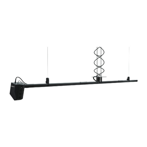
Summary of Contents for ETC Prodigy FlyPipe
- Page 1 Prodigy FlyPipe Installation Guide Part Number: 8006M2100 Rev: G Released: 2021-06...
- Page 2 To view a list of ETC trademarks and patents, go to etcconnect.com/ip. All other trademarks, both marked and not marked, are the property of their respective owners. ETC intends this document, whether printed or electronic, to be provided in its entirety.
-
Page 3: Table Of Contents
Table of Contents Introduction Document Conventions Help from ETC Technical Services Overview Safety and Warnings Working Load Limit (WLL) Hoist Specifications Interface with Building Physical Dimensions Electrical Specifications Lifting Specifications Control and Feedback Hoist Local Controls Begin Hoist Installation Tools Needed... - Page 4 Test Hoist Movement Install Slack Line Sensor Kit Adjust Timing of the Hoist Test and Adjust Adjust SafeStop Device Position for Fleet Angle Configure and Test Hoist Operation Verify Hoist Function Travel Limits Set and Test your Limits Prodigy FlyPipe Installation Guide...
- Page 5 To Set and Test the Lower Limits To Set and Test the Upper Limits Verify Hoist Address Examine the System Table of Contents...
-
Page 6: Introduction
Introduction Welcome to the Prodigy FlyPipe Installation Guide. This document provides details on how to install, test, and manually operate a FlyPipe hoist. Document Conventions This document uses the following conventions to draw your attention to important information. Note: Notes are helpful hints and information that is supplemental to the main text. -
Page 7: Help From Etc Technical Services
Help from ETC Technical Services If you are having difficulties and your problem is not addressed by this document, try the ETC support website at support.etcconnect.com or the main ETC website at etcconnect.com. If none of these resources are sufficient, contact ETC Technical Services directly at one of the offices identified below. -
Page 8: Overview
WARNING: ETC Rigging systems must be installed under the supervision of a person trained and certified in ETC Rigging Installation. If you are not an ETC Rigging trained technician, do not attempt installation of this equipment unless you are under the immediate supervision of an ETC Rigging certified installer. -
Page 9: Working Load Limit (Wll)
All Prodigy hoists have a Working Load Limit. This is identified on the product label on the side of the motor box. All Prodigy FlyPipe hoists have a Working Load Limit of 225 kg (500 lb). Prodigy Working Load Limits include a design-safety factor. -
Page 10: Electrical Specifications
Status LEDs: Provides • status when a specific travel limit has been reached Override buttons: • Allows you to move the hoist off of travel limits that have been reached Control switch: • Activates manual hoist movement Prodigy FlyPipe Installation Guide... -
Page 11: Begin Hoist Installation
(4 ft 6 in) (3 ft 6 in) Note: If your attachment points are not spaced according to the requirements above, contact your ETC Project Manager or Technical Services. For contact information, see Help from ETC Technical Services on page Begin Hoist Installation... -
Page 12: Unpack The Hoist
1. Remove the clevis pins from the exposed section of the drum shaft. To remove the clevis pin, depress the plunger and pull on the other end. 2. Shift the two sections together so they are fully joined. Prodigy FlyPipe Installation Guide... - Page 13 Shift sections together 3. Reinsert the clevis pins into the retaining holes to secure the sections. Reinsert clevis pins 4. Position the splice plates so they align with the four screw holes in the tube extrusion. Using a Phillips screwdriver, secure each splice plate with the four M5 screws. (The splice plates and screws are in a bag that is packaged in the TwinLine clamp box.) Remove cotter pin Position splice plates...
-
Page 14: Attach Twinline Clamps
The recommended torque range for this is 68–88 Nm (50– 65 ft-lb). Note: TwinLine clamps can be installed perpendicular or parallel to the strut channel. However, the clamps must always be installed perpendicular to the batten or body of the hoist. Prodigy FlyPipe Installation Guide... -
Page 15: Begin Cable Management Installation
Basic management of your power and data cables can be done using cable cradles. If you use a cable swag for your FlyPipe Studio hoist, it is recommended that you use a split mesh rod closing grip strain relief solution, such as ETC part number HW6971, at the swag hook position. Helix Cable Management... -
Page 16: Hang Helix From Upper Attachment Points
7. Once you have installed the TwinLine clamp, you must thread the TwinLine pair of wire ropes through the center grommet of each rib, beginning from the topmost rib and moving downward. Prodigy FlyPipe Installation Guide... -
Page 17: Run And Verify Hoist Electrics And Data
Chapter 4 Run and Verify Hoist Electrics and Data After the initial cable management installation, you have access to your hoist electric and data cables. It is important to run them to the appropriate connectors on the hoist and verify that the hoist is running properly before you terminate the lift lines to the drum. -
Page 18: Emergency Stop Termination
E-stop Termination Bypass Plug (ETC part # 8050B7002) into the nine-pin connector on the top of the motor box. This completes the circuit and allows you to temporarily operate the hoist from the local controls. -
Page 19: Verify Proper Wiring
If you are installing a 120/208 V hoist, you can use the Prodigy Phase Checker (ETC part number 8055A4013). For 277/480 V hoists, use a standard three-phase checker that is rated for 480 VAC, similar to the 480 V phase checker you can purchase through ETC (part# M7639). -
Page 20: Terminate Lift Lines To The Drum
2. Pull the lift lines out the bottom of the device and run them through the hoist. With the drum at top dead center, the two holes in the drum should be visible from the cutout where the SafeStop device was resting. Prodigy FlyPipe Installation Guide... -
Page 21: Step 3: Attach Stop Sleeves To Lift Lines
3. Thread the lift lines through the holes and pull them through the bottom of the hoist down to the ground. 4. Remove the self-locking clevis pins from the SafeStop brake. 5. Slide the SafeStop brake down until it rests on the hoist extrusion and then secure with the two self-locking clevis pins. -
Page 22: Step 4: Finalize Lift Line Termination
2. Pull the second lift line up through the hoist until the stopper sleeve seats into the shallow recessed groove in the drum. Prodigy FlyPipe Installation Guide... -
Page 23: Finalize Hoist And Cable Management Installation
Chapter 6 Finalize Hoist and Cable Management Installation Once you have terminated all lift lines you can finish installing the helix cable management by attaching the platter and cable assembly to the hoist. Once cable management is secured, you can float the hoist and test movement, but not before you have ensured that all SafeStop devices are latched and will not cause movement issues. -
Page 24: Attach The Platter To The Hoist
7. Tighten the four loose screws securing the bracket sides to the hoist and the four screws securing the platter to the brackets. Note: The brackets are positioned approximately 111 mm (4.37 in) from each side. Prodigy FlyPipe Installation Guide... -
Page 25: Attach Cable Assembly To Platter
Attach Cable Assembly to Platter The following instructions detail how to attach the bottom of the helix cable assembly to the platter. 1. Thread the buckles onto the nylon webbing straps Bottommost rib that extend beyond the bottommost rib. 2. Loop the nylon webbing through the slots on the platter. -
Page 26: Ensure Safestop Devices Are Open
3. Push the SafeStop latch back up into the device so it is resting above the notch on the bottom set of jaws. 4. Remove the tool and replace the plug on the top of the SafeStop device. Prodigy FlyPipe Installation Guide... -
Page 27: Float The Hoist
If you are installing a FlyPipe-XL model hoist, you must install the sensor kit that ships with the hoist before operation. For more information, refer to the Prodigy FlyPipe Slack Line Sensor Kit Installation Guide that is included in the sensor kit packaging. -
Page 28: Adjust Timing Of The Hoist
M5 screws align with the screw holes in the anchor. 6. Replace the M5 screws using the Phillips screwdriver and place the yellow end cap back on the hoist. Prodigy FlyPipe Installation Guide... -
Page 29: Test And Adjust
When adjusting the timing of the hoist, always make small incremental adjustments. Do not adjust the timing by more than a total of 1/2 turn in either direction. If the noise persists after adjustments, contact ETC Technical Services. As noted earlier, the direction in which 1/4 turn... - Page 30 If the lift lines are angled away from the brake bump on the SafeStop device, shift the device slightly to the left. If they are angled toward the brake bump, shift the device slightly to the right. When you have adjusted accordingly, tighten the set screw and replace cover that you removed. Prodigy FlyPipe Installation Guide...
-
Page 31: Configure And Test Hoist Operation
Chapter 7 Configure and Test Hoist Operation Once you've confirmed motor orientation and hung the hoist, you should perform some operational testing and set and test travel limits. Verify Hoist Function Once you have verified proper wiring and completed the E-stop circuit, you are ready to verify hoist function. -
Page 32: Travel Limits
Upper Hard Limit 8 cm (3 in) Upper Soft Limit Lower Soft Limit 8 cm (3 in) Lower Hard Limit 13 cm (5 in) Lower Overtravel Limit 13 cm (5 in) minimum to nearest point of conflict Prodigy FlyPipe Installation Guide... -
Page 33: Set And Test Your Limits
Set and Test your Limits The limit switches are located in the channel on the bottom of the pipe extrusion near the motor box. The lower limit switch is set at the lowest point of supported travel and is located closer to the motor. - Page 34 The dials represent 100s, 10s, and 1s from top to bottom. CAUTION: Failure to assign each hoist a unique address results in system errors and prevents the system from functioning properly. Prodigy FlyPipe Installation Guide...
- Page 35 Examine the System Once the installation procedure is complete, take some time to verify that all of the proper steps have been completed. Inspect all cable terminations (lift lines) to make sure they are sufficient. • Inspect all lift lines to ensure they are plumb and in the right location. •...
- Page 36 Holzkirchen, DE +49 (80 24) 47 00-0 Rome, IT +39 (06) 32 111 683 Hong Kong +852 2799 1220 Paris, FR +33 1 4243 3535 etcconnect.com Support support.etcconnect.com Contact etcconnect.com/contactETC © 2021 Electronic Theatre Controls, Inc. Trademark and patent info: etcconnect.com/ip Product information and specifications subject to change. ETC intends this document to be provided in its entirety. 8006M2100 Rev G Released 2021-06...
Need help?
Do you have a question about the Prodigy FlyPipe and is the answer not in the manual?
Questions and answers