Table of Contents
Advertisement
Quick Links
Model No. 30963.0
Serial No.
Write the serial number in the
space above for future reference.
Serial Number Decal (under seat)
QUESTIONS?
As a manufacturer, we are com-
mitted to providing complete
customer satisfaction. If you
have questions, or if parts are
damaged or missing, PLEASE
CONTACT OUR CUSTOMER
SERVICE DEPARTMENT
DIRECTLY.
CALL TOLL-FREE:
1-888-936-4266
Mon.–Fri., 8:00 until 17:00 EST
(excluding holidays)
OR E-MAIL US:
customerservice@iconcanada.ca
CAUTION
Read all precautions and instruc-
tions in this manual before
using this equipment. Save this
manual for future reference.
WEIGHT SYSTEM EXERCISER
User's Manual
w
Visit our website at
www.weiderfitness.com
Advertisement
Table of Contents

Related Manuals for WeiderPro 30963.0


Summary of Contents for WeiderPro 30963.0
- Page 1 Model No. 30963.0 Serial No. WEIGHT SYSTEM EXERCISER Write the serial number in the space above for future reference. User’s Manual Serial Number Decal (under seat) QUESTIONS? As a manufacturer, we are com- mitted to providing complete customer satisfaction. If you...
-
Page 2: Table Of Contents
TABLE OF CONTENTS WARNING DECAL PLACEMENT ............. .2 IMPORTANT PRECAUTIONS . -
Page 3: Important Precautions
IMPORTANT PRECAUTIONS WARNING: To reduce the risk of serious injury, read all important precautions and instructions in this manual and all warnings on your weight system before using the weight system. Sears assumes no responsibility for personal injury or property damage sustained by or through the use of this product. -
Page 4: Before You Begin
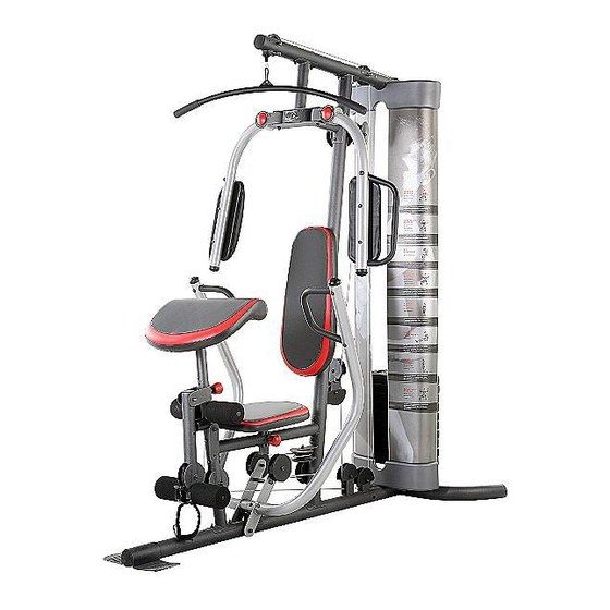
BEFORE YOU BEGIN Thank you for selecting the versatile WEIDER reading this manual, please see the front cover of this ® 4300 weight system. The weight system offers a selec- manual. To help us assist you, note the product model tion of weight stations designed to develop every major number and serial number before contacting us. -
Page 5: Part Identification Chart
PART IDENTIFICATION CHART Refer to the drawings below to identify small parts used in assembly. The number in parentheses by each draw- ing is the key number of the part, from the PART LIST near the end of this manual. Note: Some small parts may have been preattached. - Page 6 M8 x 69mm Shoulder Bolt (87) M8 x 75mm Carriage Bolt (83) M10 x 65mm Bolt (85) M10 x 75mm Bolt (82) M8 x 80mm Bolt (100) M8 x 65mm Bolt (101) M10 x 65mm Button Bolt (106) M10 x 80mm Bolt (84) M6 x 60mm Button Screw (91) M10 x 82mm Button Screw (92) M10 x 60mm Bolt (79)
- Page 7 Backrest Adjustment Knob (53) Curl Adjustment Knob (58) Seat Adjustment Knob (52)
-
Page 8: Assembly
ASSEMBLY Make sure that you have the following tools: Make Assembly Easier • Two adjustable wrenches Everything in this manual is designed to • One standard screwdriver ensure that the weight system can be assem- bled successfully by anyone. Before begin- •... -
Page 9: Frame Assembly
Frame Assembly Before beginning assembly, make sure that you understand the information in the box on page 8. See the PART IDENTIFICATION CHARTS on pages 5 and 6 of this manual for help identifying small parts. Insert four M8 x 75mm Carriage Bolts (83) up through the Base (1). - Page 10 4. Orient the Frame (9) so that the indicated hole is on the side shown. Then, attach the Frame to the Upright (2) with two M8 x 80mm Bolts (100), two M8 Washers (103), and two M8 Nylon Locknuts (78). Do not tighten the Nylon Locknuts yet. Hole Attach the Frame (9) to the Front Leg (10) with two M8 x 65mm Bolts (101), two M8 Washers...
- Page 11 7. Attach the Top Frame (4) to the Upright (2) with two M8 x 80mm Bolts (100), two M8 Washers (103), and two M8 Nylon Locknuts (78). Do not tighten the Nylon Locknuts yet. Attach the Weight Guides (18) to the Top Frame (4) with two M10 x 20mm Button Screws (96) and two M10 Washers (80).
-
Page 12: Arm Assembly
Arm Assembly 10. Attach the Butterfly Frame Brace (6) to the Upright (2) with two M8 x 80mm Bolts (100), two M8 Washers (103), and two M8 Nylon Locknuts (78). Do not tighten the Nylon Locknuts yet. 11. Apply grease in the locations shown. Insert a 56.5mm Spacer (69) the indicated hole in the Leg Grease Lever (12). - Page 13 13. Apply grease to the locations shown and attach the Left Butterfly Bracket (28) to the Butterfly Frame (5) with an M10 x 80mm Bolt (84) and an M10 Nylon Locknut (77). Repeat this step for the Right Butterfly Grease Bracket (29).
- Page 14 16. Orient a Press Arm Handle (17) with the 90° bend at the top as shown in the inset drawing. Attach a Press Arm Handle to the Right Press Arm (16) with two M10 x 65mm Button Bolts (106), four M10 Washers (80), four 11mm Spacers (99), and 90°...
-
Page 15: Cable Assembly
Cable Assembly 19. See the CABLE DIAGRAMS on page 28 to identi- fy the cables as you assemble them. Grease Identify the Butterfly Cable (50). Grease an M8 x 22mm Shoulder Bolt (90). Attach the Cable to the Left Butterfly Bracket (28) with the Shoulder Bolt and an M8 Nylon Locknut (78). - Page 16 22. Wrap the Butterfly Cable (50) over a “V”-pulley (47). Attach the “V”-pulley, a Long Cable Trap (57), an M10 Washer (80), and two Guards (54) to the Upright (2) with an M10 x 60mm Bolt (79) and an M10 Nylon Locknut (77). 23.
- Page 17 25. Route the Lat Cable (49) over a Thin Pulley (24) and down through the Top Frame (4). Hold the Thin Pulley inside the Top Frame. Insert an M10 x 80mm Bolt (84) through an M10 Washer (80), a 19mm Spacer (67), the Top Frame, and the Thin Pulley.
- Page 18 28. Wrap the Lat Cable (49) around a 90mm Pulley (48) and route the Cable down through the Top Frame (4). Attach the Pulley to the Top Frame with an M10 x 80mm Bolt (84), two M10 Washers (80), two 19mm Spacers (67), and an M10 Nylon Locknut (77).
- Page 19 31. Attach a 90mm Pulley (48) to the Front Leg (10) with an M10 x 65mm Bolt (85), two M10 Washers (80), two 13mm Steel Spacers (109), and an M10 Nylon Locknut (77). Make sure that the Leg Lever Cable (51) is under the Pulley. 32.
- Page 20 34. Wrap the Leg Lever Cable (51) under a 90mm Pulley (48). Attach the Pulley to the Base (1) with an M10 x 45mm Bolt (86), two Half Guards (55), and an M10 Nylon Locknut (77). 35. Wrap the Leg Lever Cable (51) over a 90mm Pulley (48).
- Page 21 37. Wrap the Leg Lever Cable (51) under a 90mm Pulley (48). Attach the Pulley to the Right Press Arm (16) with an M10 x 50mm Bolt (97), two Half Guards (55), a Cable Trap (56), an M10 Washer (80), and an M10 Nylon Locknut (77). Make sure that the Cable Trap and Half Guards are orient- ed as shown.
-
Page 22: M6 X 60Mm Button
40. Attach the Leg Lever Cable (51) to the Upright (2) with the M10 x 120mm Bbolt (115), an M10 Washer (80), a 7mm Spacer (111), and an M10 Nylon Locknut (77). Make sure that the flat edge of the Cable is against the Spacer. Flat Edge Seat Assembly 41. - Page 23 43. Attach the Seat (32) to the Seat Frame (8) with two M6 x 16mm Screws (88), an M6 x 32mm Screw (89), and an M6 Washer (114). Insert the Seat Frame (8) into the Frame (9). Tighten the Seat Adjustment Knob (52) into the Frame and the Seat Frame.
- Page 24 46. Attach the Curl Pad (33) to the Curl Post (11) with two M6 x 16mm Screws (88). 47. Make sure that all parts have been properly tightened. The use of the remaining parts will be explained in ADJUSTMENTS, beginning on the following page. Before using the weight system, pull each cable a few times to make sure that the cables move smoothly over the pulleys.
-
Page 25: Adjustments
ADJUSTMENTS This section explains how to adjust the weight system. Refer to the accompanying exercise guide to see the cor- rect form for each exercise. Make sure that all parts are properly tightened each time the weight system is used. Replace any worn parts immediately. - Page 26 USING THE CURL PAD To use the Curl Pad (33), remove the indicated 50mm Round Inner Cap (39) and insert the Curl Post (11) into the Front Leg (10). Tighten the Curl Adjustment Knob (58) into the Front Leg. Make sure that the Adjustment Knob passes through a hole in the Curl Post.
-
Page 27: Weight Resistance Chart
LOCKING THE LEG LEVER To lock or unlock the Leg Lever (12), remove the Lock Plate Pin (95) from the Lock Plate (14). Move the Lock Plate to either the position shown on the Front Leg (10), or the indicated hole in the Leg Lever. Insert the Lock Pin back through the Lock Plate. -
Page 28: Cable Diagram
CABLE DIAGRAM The cable diagram shows the proper routing of the cables (49, 50, 51). Use the diagram to make sure that the cable and the cable traps have been assembled correctly. If the cable has not been correctly routed, the weight system will not function properly and damage may occur. -
Page 29: Maintenance
MAINTENANCE Make sure that all parts are properly tightened each time the weight system is used. Replace any worn parts immediately. The weight system can be cleaned with a damp cloth and a mild, non-abrasive detergent. Do not use solvents. TIGHTENING THE CABLES Woven cable, the type of cable used on the weight system, can stretch slightly when it is first used. -
Page 30: Exercise Guidelines
EXERCISE GUIDELINES THE FOUR BASIC TYPES OF WORKOUTS PERSONALIZING YOUR EXERCISE PROGRAM Muscle Building Determining the appropriate length of time for each To increase the size and strength of your muscles, workout, and the numbers of repetitions and sets to push them close to their maximum capacity. - Page 31 Rest for a short period of time after each set. The slowly as you stretch and do not bounce. Ease into ideal resting periods follow: each stretch gradually and go only as far as you can • Rest for three minutes after each set for a muscle without strain.
- Page 32 EXERCISE WEIGHT SETS REPS MONDAY Date: AEROBIC EXERCISE TUESDAY Date: EXERCISE WEIGHT SETS REPS WEDNESDAY Date: THURSDAY AEROBIC EXERCISE Date: EXERCISE WEIGHT SETS REPS FRIDAY Date: Make photocopies of this page for scheduling and recording your workouts.
-
Page 33: Part List
PART LIST—Model No. 30963.0 R0607A Qty. Description Qty. Description Qty. Description Base Butterfly Arm Cap M8 x 69mm Shoulder Upright Bolt Cap Bolt Stabilizer Butterfly Arm Bushing M6 x 16mm Screw Top Frame Butterfly Bracket M6 x 32mm Screw Butterfly Frame... -
Page 34: Exploded Drawing
EXPLODED DRAWING A—Model No. 30963.0 R0607A 70 71... - Page 35 EXPLODED DRAWING B—Model No. 30963.0 R0607A...
-
Page 36: Ordering Replacement Parts
ORDERING REPLACEMENT PARTS To order replacement parts, please see the front cover of this manual. To help us assist you, be prepared to provide the following information when contacting us: • the model number and the serial number of the product (see the front cover of this manual) •...