WeiderPro Pro 4000 User Manual
Uk manual
Hide thumbs
Also See for Pro 4000:
- Manual del usuario (32 pages) ,
- Gebruikershandleiding (28 pages) ,
- Manuale d'istruzioni (28 pages)
Table of Contents
Advertisement
Model No. WEEVSY2826.0
Serial No.
Write the serial number in the
space above for future reference.
Serial Number Decal (Under Seat)
QUESTIONS?
As a manufacturer, we are com-
mitted to providing complete
customer satisfaction. If you
have questions, or if there are
missing or damaged parts,
please call:
08457 089 009
Or write:
ICON Health & Fitness, Ltd.
Unit 4
Revie Road Industrial Estate
Revie Road, Beeston
Leeds, LS11 8JG
UK
email: csuk@iconeurope.com
CAUTION
Read all precautions and instruc-
tions in this manual before using
this equipment. Save this manual
for future reference.
USER'S MANUAL
Advertisement
Table of Contents

Subscribe to Our Youtube Channel
Related Manuals for WeiderPro Pro 4000


Summary of Contents for WeiderPro Pro 4000
- Page 1 Model No. WEEVSY2826.0 Serial No. Write the serial number in the USER’S MANUAL space above for future reference. Serial Number Decal (Under Seat) QUESTIONS? As a manufacturer, we are com- mitted to providing complete customer satisfaction. If you have questions, or if there are missing or damaged parts, please call: 08457 089 009...
-
Page 2: Table Of Contents
Apply the decal in the location shown. VERTICAL WARNING PN 218558 – Black Text/Clear Background PN 218559 – White Text/Clear Background WEIDER is a registered trademark of ICON IP, Inc. -
Page 3: Important Precautions
IMPORTANT PRECAUTIONS WARNING: To reduce the risk of serious injury, read the following important precautions before using the weight system. 1. Read all instructions in this manual and all 6. Keep children under 12 and pets away from warnings on the weight system before using the weight system at all times. -
Page 4: Before You Begin
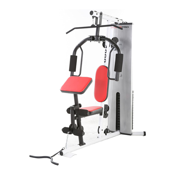
BEFORE YOU BEGIN Thank you for selecting the versatile WEIDER ® reading this manual, please see the front cover of this 4000 weight system. The weight system offers a selec- manual. To help us assist you, please note the product tion of weight stations designed to develop every model number and serial number before contacting us. -
Page 5: Assembly
ASSEMBLY Make sure you have the following tools: Make Assembly Easier • Two adjustable spanners Everything in this manual is designed to • One standard screwdriver ensure that the weight system can be assem- bled successfully by anyone. Before begin- •... - Page 6 Frame Assembly Before beginning assembly, make sure you understand the information in the box on page 5. Refer to the PART IDENTI- FICATION CHART in the centre of this manual for help identifying small parts. Insert four M8 x 74mm Carriage Bolts (78) up through the Base (1).
- Page 7 3. Attach the Front Leg (7) to the Base (1) with the two indicated M8 x 74mm Carriage Bolts (78) and two M8 Nylon Locknuts (58). Do not tight- en the Nylon Locknuts yet. Attach the Leg Bumper (60) to the Front Leg (7) with an M4 x 19mm Screw (69).
- Page 8 6. Attach the Top Frame (4) to the Upright (3) with two M8 x 77mm Button Bolts (68), two M8 Washers (59), and two M8 Nylon Locknuts (58). Do not tighten the Nylon Locknuts yet. Attach the Top Frame (4) between the Weight Guides (21) with an M10 x 155mm Button Bolt (74), two M10 Washers (57), two 13mm Spacers (76), and an M10 Nylon Locknut (56).
- Page 9 8. Attach the Shroud (17) to the Top Frame (4) with two M4 x 16mm Screws (86). Attach the Shroud (17) to the brackets on the Stabilizer (2) with two M4 x 16mm Screws (86). Make sure the brackets are inside the Shroud.
- Page 10 11. Grease an M10 x 52mm Button Bolt (66). Attach a Cable Pivot (39) to the Right Arm (9) Grease with the Button Bolt and an M10 Nylon Locknut (56). Do not overtighten the Nylon Locknut; the Cable Pivot must pivot freely. Wet the inside of a Large Foam Pad (42) with soapy water.
- Page 11 14. Route the Arm Cable (54) over a “V”-pulley (46). Attach the “V”-pulley, a Large Cable Trap (50), and two Guards (41) to the Upright (3) with an M10 x 62mm Button Bolt (75) and an M10 Nylon Locknut (56). Make sure the Cable Trap is oriented to hold the Cable in the groove of the “V”-pulley.
- Page 12 18. Identify the High Cable (55). Route the Cable up through the Top Frame (4) and over a 90mm Pulley (48). Attach the Pulley inside of the Top Frame with an M10 x 78mm Button Bolt (71), two M10 Washers (57), two 19mm Spacers (33), and an M10 Nylon Locknut (56).
- Page 13 22. Route the High Cable (55) over a 90mm Pulley (48) and down through the Top Frame (4). Attach the Pulley inside of the Top Frame with an M10 x 78mm Button Bolt (71), two M10 Washers (57), two 19mm Spacers (33), and an M10 Nylon Locknut (56).
- Page 14 25. Attach a 90mm Pulley (48) inside of the Front Leg (7), over the Low Cable (53), with an M10 x 78mm Button Bolt (71), two M10 Washers (57), two 19mm Spacers (52), and an M10 Nylon Locknut (56). 26. Attach a 90mm Pulley (48) inside of the Upright (3), over the Low Cable (53), with an M10 x 78mm Button Bolt (71), two M10 Washers (57), two 19mm Spacers (33), and an M10 Nylon...
- Page 15 29. Route the Low Cable (53) over a 90mm Pulley (48). Attach the Pulley, a Cable Trap (51), and two Half Guards (43) to the Adjustable “U”- bracket (45) with an M10 x 52mm Button Bolt (66) and an M10 Nylon Locknut (56). 30.
- Page 16 33. Insert the Pad Tube (29) into the Front Leg (7). Slide two Small Foam Pads (28) onto the Pad Tube. Then, press two Pad Caps (34) onto the Pad Tube. Slide two Small Foam Pads (28) onto the Leg Lever (8).
-
Page 17: Adjustments
ADJUSTMENTS This section explains how to adjust the weight system. See the EXERCISE GUIDELINES on page 22 for impor- tant information about how to get the most benefit from your exercise program. Also, refer to the accompanying exercise guide to see the correct form for each exercise. Make sure all parts are properly tightened each time the weight system is used. - Page 18 ARM CONVERSION To use the Arms (9, 10) as butterfly arms, insert the Arm Pins (40) into the holes in the Upright (3) and the Pivot Frame (5) as shown. To use the Arms (9, 10) as press arms, insert the Arm Pins (40) into the holes in the Pivot Frame (5) and the Arms.
-
Page 19: Weight Resistance Chart
WEIGHT RESISTANCE CHART The chart below shows the approximate weight resistance at each exercise station. “Top” refers to the 6 lb. top weight. The other numbers refer to the 12.5 lb. weight plates. Weight resistance shown for the butterfly arm sta- tion is for each arm. -
Page 20: Cable Diagrams
CABLE DIAGRAMS The cable diagrams below show the proper routing of the Low Cable (53), the Arm Cable (54), and the High Cable (55). Use the diagrams to make sure that the cables, cable traps, and finger guards have been assem- bled correctly. -
Page 21: Maintenance
MAINTENANCE Make sure all parts are properly tightened each time the weight system is used. Replace any worn parts imme- diately. The weight system can be cleaned with a damp cloth and a mild, non-abrasive detergent. Do not use solvents. TIGHTENING THE CABLES Woven cable, the type of cable used on the weight system, can stretch slightly when it is first used. -
Page 22: Exercise Guidelines
EXERCISE GUIDELINES THE FOUR BASIC TYPES OF WORKOUTS PERSONALISING YOUR EXERCISE PROGRAM Muscle Building Determining the exact length of time for each workout, To increase the size and strength of your muscles, as well as the number of repetitions or sets completed, push them close to their maximum capacity. - Page 23 Rest for a short period of time after each set. The slowly as you stretch and do not bounce. Ease into ideal resting periods follow: each stretch gradually and go only as far as you can • Rest for three minutes after each set for a muscle without strain.
-
Page 24: M10 X 72Mm Button Bolt (85)
PART IDENTIFICATION CHART Refer to the drawings below to identify small parts used in assembly. The number in parentheses by each draw- ing is the key number of the part, from the PART LIST in the centre of this manual. Note: Some small parts may have been pre-attached. - Page 25 PART LIST—Model No. WEEVSY2826.0 R0706A Key No. Qty. Description Key No. Qty. Description Base 90mm Thin Pulley Stabilizer 90mm Pulley Upright 57mm Round Inner Cap Top Frame Large Cable Trap Pivot Frame Cable Trap Seat Frame 16mm Spacer Front Leg Low Cable Leg Lever Arm Cable...
- Page 26 EXPLODED DRAWING A—Model No. WEEVSY2826.0 R0706A 44 56...
- Page 27 EXPLODED DRAWING B—Model No. WEEVSY2826.0 R0706A 41 75...
-
Page 28: Ordering Replacement Parts
To help us assist you, please be prepared to give the following information: • the MODEL NUMBER of the product (WEEVSY2826.0) • the NAME of the product (WEIDER PRO 4000 weight system) • the SERIAL NUMBER of the product (see the front cover of this manual) •...
Need help?
Do you have a question about the Pro 4000 and is the answer not in the manual?
Questions and answers