Table of Contents

Related Manuals for Cannon CANT


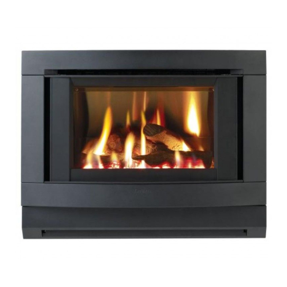
Summary of Contents for Cannon CANT
- Page 1 Cannon MAKER’S WARRANTY FREESTANDER MODELS CANT, CANTLP USER INSTRUCTIONS INSTALLATION INSTRUCTIONS This heater is approved for use with Natural and Propane gases. SERVICE INSTRUCTIONS Please leave instructions with the owner...
-
Page 2: Table Of Contents
Contents Contents Warranty Safety warnings ❍ What to do if you smell gas ❍ Warnings ❍ Standards User instructions ❍ Operating instructions ❍ Cleaning Heater specifications ❍ Alternative flue Installation instructions ❍ Clearances ❍ Installation ❍ Gas connection ❍ Fuel bed & log installation ❍... -
Page 3: Warranty
Australia. Warranty service, which includes parts and labour for the replace- ment or repair of defective parts, is available through Cannon Authorised Service Agencies. (Please refer to the list of authorised service agents in this manual.) Consumers are responsible for service person’s travel outside nor-... -
Page 4: Safety Warnings
Safety Warnings Please read this manual before installing and using the heater. 1. Turn OFF the main gas supply. What to do if you smell 2. Extinguish any open flame. 3. Open windows. 4. Do not touch electrical switches. 5. Do not use your telephone. 6. -
Page 5: Standards
9. The appliance should be inspected prior to use, with regular inspections (annually) to be made by a licensed service per- son. It is important that circulating air passageways of the appliance be kept clean, dirt and lint free, for a safe and efficient operation of the heater. -
Page 6: User Instructions
User instructions Operating instructions The Australian Gas Association: AG 103 1. Plug the power cord into the wall socket and turn on the power to the heater, see figure 1. Use of an extension cord is not recommended 2. For control lay-out refer to figure 2 3. - Page 7 5. To increase the fan speed to MED, press switch for MED set- ting. Refer figure 5. 6. To increase the fan speed to HIGH, press switch for HIGH setting. Refer figure 6. 7. To turn the burner to LOW setting, press switch for LOW set- ting.
-
Page 8: Cleaning
User instructions continued Cleaning. All cleaning should be carried out when the heater is cold. Nor- mally the heater should only need wiping with a lint - free damp cloth. Any stubborn stains can be removed with a non-abrasive spray on cleaner. If an abrasive cleaner is used the paint finish will be damaged. -
Page 10: Installation Instructions
Installation Instructions 1. This appliance is to be installed by a licensed service person only. 2. This appliance is to be installed in accordance with the manufacturer’s installation instructions, AS 5601/AG601, Municipal Building Codes, Electrical Wiring Regulations and any other statutory regulations. 3. -
Page 11: Gas Connection
9. Remove the front glass surround by holding it firmly on either side and pulling it towards yourself, see figure 13. 10.Remove the inner glass. Slacken off screws in top clamp and remove side clamps. Refer figure 14. Gas connection 11. -
Page 12: Fuel Bed & Log Installation
Installation instructions continued 12. The fuel bed is contained within the burner chamber. Remove Fuel bed and log the fuel bed transit packaging. Refer figure 16. installation The fuel bed is retained by a spring clip fixed to the rear of the burner chamber FUEL BED MUST BE HARD UP AGAINST REAR OF BURNER 13. -
Page 13: Gas Pressure Point
d) Place log No. 4 on single right back pin, ensure left side of log rests on depression in No. 3 log, see figure 20. 14. Refit the inner glass, but do not overtighten the screws. 15. Refit the front glass surround. Ensure that the glass surround is replaced the correct side up. -
Page 14: Flue Installation
Flue installation This heater is a flued appliance. It must be properly connected to a flue system in accordance with the latest edition of the Gas Installa- tion Code, AS 5601/AG 601. If elbows are needed, the total horizontal length depends on the number of elbows used. -
Page 16: Alternative Double Skin Flue Installation
Installation instructions continued Alternative double skin This heater is a flued appliance. It must be properly connected to a flue system in accordance with the latest edition of the Gas Installa- flue installation tion Code, AS 5601/AG 601. If elbows are needed, the total horizontal length depends on the number of elbows used. -
Page 18: Service Instructions
Service Instructions General 1. Service work to be carried out by a licensed service person only. 2. Unplug from wall socket. 3. Always shut off the gas supply and ensure that the heater is cool before commencing any service operations. 4. -
Page 19: Troubleshooting
2. Remove the logs and the fuel bed from the burner chamber. 3. Disconnect the compression nut at the back of the burner now visible through the primary baffle. 4. Remove lower front panel. 5. Remove the four M5 screws fixing the burner chamber fascia in position and slide out taking a note of the “P”... -
Page 20: Wiring Diagram
Service instructions continued Authorised service agents For further information or spare parts con- tact the CANNON distributor in your state. Sampford & Staff Pty Ltd 421 Smith Street. Fitzroy, Vic, 3065 Vic/Tas: (03) 9418 5800 NSW: (02) 9331 8888 SA/NT:...
Need help?
Do you have a question about the CANT and is the answer not in the manual?
Questions and answers