Table of Contents
Advertisement
Quick Links
Data label
Stick copy of data label here!
Date installed: ........................................
Compliance Certificate No .........................
For service to this appliance or spare
parts contact the CANNON distributor:
Sampford IXL (spare parts)
52 - 70 Sparks Avenue
Fairfield, Vic, 3078
Phone: 1300 727 421
Fax:
1300 727 425
email: service@sampfordixl.com.au
24
USER INSTRUCTIONS
INSTALLATION INSTRUCTIONS
SERVICE INSTRUCTIONS
INBUILT MODELS
Cannon
Part No: F2901
RevisionG- 2010
CANTERBURY
PLEASE READ THIS MANUAL
BEFORE INSTALLING AND
Gmk10025
Please leave instructions with the owner
AS4553:2008
Cannon
USING THIS HEATER.
This heater is approved for use with
Natural and Propane gases.
Advertisement
Table of Contents

Summary of Contents for Cannon CANTERBUR
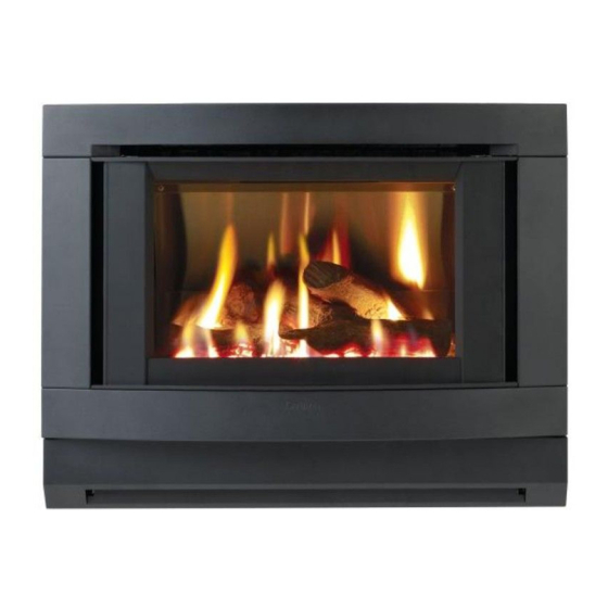
- Page 1 INBUILT MODELS PLEASE READ THIS MANUAL BEFORE INSTALLING AND For service to this appliance or spare USING THIS HEATER. parts contact the CANNON distributor: Cannon Sampford IXL (spare parts) 52 - 70 Sparks Avenue This heater is approved for use with...
-
Page 2: Table Of Contents
Contents Contents Sparks, ignites on low flame • Check that the wall socket to the appliance has Warranty then extinguishes after 10 correct polarity. Do not use an extension cord. Check Distributor seconds. Continues to spark polarity in the electrical supply lead to appliance. during flame presence. -
Page 3: Warranty
(Do not modify this appliance) Warranty The Cannon appliance is warranted against defects in materials and work- To check the operation of the electronic (module) controller (Techrite ) you will require a manship for a period of one, (1) year from its date of original purchase, for digital multimeter with the functions to measure AC/DC voltage, continuity, resistance and residential use in Australia. -
Page 4: Safety Warnings
7. Replace in reverse order checking location of spark/sense elec- licensed plumber, a gas supplier or the CANNON distributor listed in trodes, refer page 23, figure 36. Spark gap between electrode this manual. -
Page 5: Standards
This is to 7. Replace silicon tube onto fan pressure switch and reconnect fan test that there is no interaction between the Cannon heater and other plug into plug carrier. -
Page 6: User Instructions
User instructions Service instructions (Do not modify this appliance) General Operating instructions 1. Service work to be carried out by an authorised service person only. 1. Plug the power cord into the wall socket and turn on the power to the 2. -
Page 7: Cleaning
Be careful! All cleaning should be carried out when the heater is cold. Clean the outer CANNON heaters are high efficiency products with low flue gas tempera- glass with a liquid solution ‘Windex’ or similar. tures (typically 100 C) so if you are replacing an older type radiant heater... -
Page 8: Heater Specifications
Heater specifications Gas pressure point Gas type: Natural or Propane gas, as indicated 24.The pressure point is closed with a captive screw. Turn screw 6 revolu- Note: on data label tions anticlockwise to open the pressure point as indicated on figure The data plate is located on 33(a) and place manometer tube over the test point as per figure 33(b). -
Page 9: Installation Instructions
5.Models CANTIB-NG & CANTIB-LP can be installed onto a masonry/ brick fireplace or mock fireplace. If installing into a mock fireplace a mock fireplace installation kit MUST be used. The mock fireplace installation kit can be ordered from the CANNON distributor. Order specification for the part is ‘MOCKKITRO’. -
Page 10: Installation With A Flue Connected
If an exhaust fan or other heating appliances are present switch them on. This is to test that there is no interaction between the CANNON heater and other appliances. Refer AS5601. -
Page 11: Connections
Gas connection Installation WITHOUT a flue connection. 13. Slide heater into the fireplace ensuring that gas inlet pipe is fed through the hole at the rear bottom RHS of the heater. Refer figure 22 and gas connection figure 24. 14.With heater in position, flanges should be hard against masonry. Se- cure case flanges to masonry. - Page 12 6. Prepare electrical and gas connections. Remove the lower front cover, see figure 16. A 10 Amp wall socket needs to be located within 1.5m of the heater. If using a power point in the chimney, route the plug and cord through cord access at lower LH side of rear panel.


Need help?
Do you have a question about the CANTERBUR and is the answer not in the manual?
Questions and answers