Table of Contents
Advertisement
Quick Links
Advertisement
Table of Contents

Related Manuals for Avermedia XR8032


Summary of Contents for Avermedia XR8032
- Page 1 ® AVerMedia XR8032 User’s Manual...
- Page 2 In no event will AVerMedia be liable for direct, indirect, special, incidental, or consequential damages arising out of the use or inability to use this product or documentation, even if advised of the possibility of such damages.
- Page 3 WARNING TO REDUCE RISK OF FIRE OR ELECTRIC SHOCK, DO NOT EXPOSE THIS APPLIANCE TO RAIN OR MOISTURE. CAUTION IF THERE IS ANY DAMAGE, SHORTAGE OR INAPPROPRIATE ITEM IN THE PACKAGE, PLEASE CONTACT WITH YOUR LOCAL DEALER. WARRANTY VOID FOR ANY UNAUTHORIZED PRODUCT MODIFICATION.
-
Page 4: Table Of Contents
TABLE OF CONTENTS Chapter 1 Introduction................1 1.1 Package Contents ..................... 1 1.2 Front Panel ........................ 1 1.3 Back Panel......................... 2 1.4 Connecting Device..................... 2 1.5 Connecting POS (Point of Sales)................3 1.6 Connecting the Sensor/Relay device................. 4 Chapter 2 Using the DVR Software............5 2.1 Running the Unit for the First Time ................ - Page 5 3.8 Relay Setting ......................39 3.9 Alarm Setting ......................39 3.9.1 To Setup Alarm Relay:................... 43 3.9.2 To Setup the Alarm Sound Setting: ............... 44 3.9.3 To Setup Call Out List: .................. 44 3.9.4 To Setup Send E-mail Setting: ..............45 3.9.5 To Setup FTP Setting: ...................
- Page 6 Chapter 9 Web Tools................. 76 9.1 Dispatch Server ....................... 76 9.2 Remote Backup ....................... 76 Chapter 10 Using the Remote Control Server ........79 Appendix A Registering Domain Names..........80...
-
Page 7: Chapter 1 Introduction
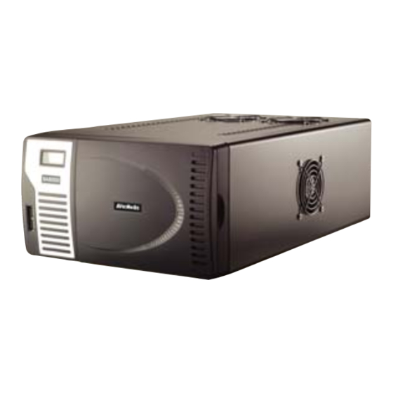
XR8032 is a standalone DVR unit that through the network to receive video and monitoring and recording of video. It can connect 8 sensors and relays. The XR8032 is customized to use it right away. No more software and hardware installation. Just connect the cables and you may now start video surveillance. -
Page 8: Back Panel
Back Panel (11) (10) (9) (6) Name Function (1) Audio Out Output the audio of the selected video channel The audio output device needs to be powered by external power. (2) TV Out Output the video signal to a CCTV monitor (3) Sensor In Relay Out Support 8 sensor devices and 8 relay devices (Relay: 1A @ 125V AC/30V DC) -
Page 9: Connecting Pos (Point Of Sales)
® AVerMedia XR8032 can be integrated with POS system equipment. Connecting the POS equipment to DVR system thru RS232 connection, enables you to view, record and keep track of the items that were sold. You may also select the camera on where to display all the data. -
Page 10: Connecting The Sensor/Relay Device
Connecting the Sensor/Relay device The I/O card enables you to connect (8) sensor inputs and (8) relay outputs. Just connect the external sensor and relay pin directly to the I/O card pinhole. Check the table below and locate which pinhole is assigned to sensor input and relay output. The two set of I/O card pinhole are the same. -
Page 11: Chapter 2 Using The Dvr Software
Chapter 2 Using the DVR Software Running the Unit for the First Time When the unit is turned on for the first time, the system will prompt you to enter the serial number. The serial number is inside the package. Function buttons of Advanced/Preview Mode (17) (16) - Page 12 Name Function (3) Split Screen It provides 7 kinds of split display modes for your selection. You Mode can select one of the split display modes by clicking the following icon. 1-Cam display 4-Cam split display 9-Cam split display 16-Cam split display 8-Cam split display 13-Cam split display 32-Cam split display...
-
Page 13: Using Event Log Viewer
Name Function Click it to turn to full screen mode. To return, press the right button of (16) Full screen the mouse or ESC on the keyboard or click the arrow icon. Click arrow icon to leave from full screen display mode When you switch to full screen in multiple-screen mode, Left click to toggle to only display one of the video in the multiple-screen mode... - Page 14 Name Function (1) POSDB Path The storage path for POS event log. Click to change the storage path. (2) Before/After Set a time period before and after of POS event log. (3) Channel Select the POS event log of channel (4) Search String Enter specific key word or word string to search the POS event log.
-
Page 15: Familiarizing The Buttons In Playback Mode
Familiarizing the Buttons in Playback Mode To switch in Playback mode, click Playback button at the lower right corner of Advanced/Preview mode user interface Name Function Select from 6 kinds of split screen type to playback the recorded (1) Split Screen Mode video file of all the cameras, or one camera over the other or alongside on a single screen. - Page 16 Name Function (4) Playback Control Faster: Play the recorded video file at the speed of 2x, 4x, 8x, 16x Buttons or 32x. Next: Go to the next frame. End: Go to the end of the recorded video file. Select the date on the calendar and the time from 00 to 23 to where (5) Date to start playing the recorded video file.
-
Page 17: Familiarizing The Buttons In Compact Mode
Name Function You can use this when you are using Intelligent Search or Event Search function. (19) Event Search Search from the recorded activities that take place in the system (i.e., Sensor, Motion, Video Loss, POS). (See also 2.10) (20) Intelligent Search Search the changes in the motion detector frame (See also 2.11). -
Page 18: Familiarizing The Buttons In Ptz Camera Controller
(5) Advanced Switch to Preview/Advanced mode. Familiarizing the Buttons in PTZ Camera Controller (10) Name Function (1) Close Exit PTZ camera controller. (2) AutoPan Operate the PTZ cameras automatically based on the selected camera group preset position number. (3) Focus +/- Adjust the focus manually to produce clear image. -
Page 19: To Use The Emap
camera, sensor, and relay icons to its place on the map. Icons on the map can be relocated anywhere. Right click camera icon can select the camera direction in 8 angles. If you are going to locate the icon on the map to other area, you need to drag the icon to the black pane at the bottom of the Emap screen and then switch to the area on where you want to locate the icon. -
Page 20: To Bookmark A Section Of The Video
again. Click Output button to save the wanted clip. In the Save As dialog box, locate on where you want to save the file, type the filename, and select the video format. To Bookmark a Section of the Video Click Bookmark. The video playback stops when the bookmark button is executed. In the Bookmark dialog box, you may do the following: Add to include the new reference mark in the bookmark list. -
Page 21: To Search Using The Event Search
2.10 To Search Using the Event Search Click on the video screen on where you want to search. Click Event Search. The Event Search text (red) would appear at the lower left corner of the screen. In the Event Search Setting dialog box, check the type of condition you want to search. If you select POS, in the Find Text box, type the word. -
Page 22: To Setup The Ptz/Ip Ptz Camera
2.12 To Setup the PTZ/IP PTZ Camera 2.12.1 Setup the PTZ Camera 1. In the PTZ control panel, click Setup. 2. When the PTZ Setup dialog box appears, select the camera number and check the Use PTZ box. 3. In the Connection Settings section, select the COMPort where the PTZ camera is connected, PTZ ID number and PTZ camera protocol. - Page 23 3. Select the camera number and check the Use PTZ box. 4. In the Connection Settings section, select the Protocol where the PTZ camera is connected and IP Camera Site that IP or URL of IP camera. Then, click Save to keep the settings.
-
Page 24: Chapter 3 Customizing The Dvr System
Chapter 3 Customizing the DVR System In the Preview/Advanced screen mode, click button to customize your DVR. When the DVR configuration setup selection appears, select and click the buttons you want to change the setting. System Setting In the System Setting dialog box, click OK to accept the new settings, click Cancel to exit without saving, and click Default to revert back to original factory setting. - Page 25 time in Expected HD Size or Expected Record time, and then click Calculate button. Click OK to exit the hard disk calculator windows. The hard disk calculation will base on the recording setup and current hard disk setup. (3)Language Customize the system to display the tool tips and dialogs based on the selected language. By default the language is in English.
- Page 26 Fixed Layout (1) Select the channel group from drop down list. If only have 16 cameras or less 16 cameras, there is only one channel group in the drop down list. (2) Select the display mode as FixedLayout. (3) Preview screen: the selected camera video will preview in here. (4) Video Mode: Select the split mode of TV out display.
-
Page 27: To Set The Pos Setting
click Setup. - Beep if no signal Make sound when the video signal is lost. - Mandatory Recording Always recording the video in any condition. - Enable Overlay To enhance video signal for better video quality. - Playback Mode Select the mode of playback the video. Select date and time: Select the date and time which user wants to playback. - Page 28 In the POS Mapping dialog box, click OK to accept the settings and Cancel to exit without saving the new setting. : Enter a name to identify the POS (1) POS Name : Select General for Epson compatible printer or for TP_3688 (2) Protocol : Set the number of lines you want to be removed (3) Skip first...
- Page 29 (6) Map to Channel: Select to which camera number to display the transaction text : Enter the word you want to be removed (7) Text Filter...
-
Page 30: Camera Setting
Camera Setting In the Camera Setting dialog box, click OK to accept the new settings, click Cancel to exit without saving, and click Default to revert back to original factory setting. (11) (13) (10) (12) (1) Camera Icons Select the camera number you want to adjust the video setting. To select all the cameras, enable the ALL check box. - Page 31 Authentication: Mark check box and enter the ID and password for authorizing to connect the camera. Only if the camera has assign the ID and password for authentication. (5) Camera Information Display the camera information, such as camera protocol, model, video type, IP address, and channel number.
- Page 32 (10) Video Adjust the video setting of the selected camera. Click Video Setting to enter video adjustment interface. Video Setting Adjust the Frame Rate, Quality, Bright, Contrast, Hue, and Saturation. Recording Setting Save Original Format: Save the video that is compressed by IP camera’s compress mode.
- Page 33 (12) Sensor Setting To setup sensor that is embedded on the camera. Click the drop-down list and select the sensor ID number. Enter sensor name. The system automatically detects the camera and input relates information. In the Content section, enter sensor description. In the test section, click Test to check the sensor status.
-
Page 34: Setup The Object Counting
3.2.1 Setup the Object Counting 1. Click Detail to enter the object counting setup window. 2. Enable Detected Regions in Display section. This enables the object counting information show on the screen. Moving Object will enable the object size frame to show on the screen. - Page 35 without saving, and click Default to revert back to original factory setting. (10) (1) Camera Icons Select the camera number you want to set the recording setting. To select all the cameras, enable the ALL check box. To select more than one camera, Right click on the camera icon.
-
Page 36: To Mask/Shield An Area On The Screen
(5) Frame Rate Set the maximum number of frames to be recorded during motion and motionless state. The frame rate ranges from 1 to 30 for NTSC and 1 to 25 for PAL. The higher the frame rate, it uses more hard disk space. Only available when user selected “Transcode by MPEG4 Encoder”... -
Page 37: To Show And Change The Color Of The Mask
Click and drag a frame on the (7) Video Screen to create Mask or Shield area. Shield is only available when user selected “Transcode by MPEG4 Encoder” in Video Setting at Camera setting section(see Chapter 3.2 3.3.2 To show and change the color of the Mask: Enable the Show Mask check box. -
Page 38: Network Setting
Network Setting In the Network Setting dialog box, click OK to accept the new settings, click Cancel to exit without saving, and click Default to revert back to original factory setting. (10) (1) Server Name Assign a name for the DVR unit. Alphabet letters and numbers only. (2) Transmitting Cameras Select and click on the camera number in the Transmitting Camera section you want to make it accessible via internet using WebViewer, Remote Console, PDA Viewer and Hand... - Page 39 using this feature. If the Talk to Web-Client is disabled, the person in the DVR server side can only hear the voice from the client side that is when the WebViewer 2-Way Talk button is activated (see also #6). Make sure that your Webcam Digital Signature is updated yearly; else you won’t be able to access the DVR server from the DVR WebViewer.
-
Page 40: Schedule Setting
Schedule Setting Schedule to record, backup, enable network, reboot and disable alarm of all the cameras either weekly or one time. The number from 00 to 23 represent the time in 24-hour clock. The left most column display the days in a week. To Set the Schedule Setting: Select the date in the calendar. -
Page 41: Set Schedule At Specific Portion Of Time
3.5.1 Set schedule at specific portion of time Right click the colored blocks. In the Select time dialog box, click to enable or disable the portion you want to set. Click OK to accept the setting and Cancel to exit without saving the setting. Backup Setting In the Backup Setting dialog box, the number from 00 to 23 represent the time in 24-hour clock. -
Page 42: Sensor Setting
In CD/DVD Backup, enable/disable Delete file after burning check box to remove the archived file after burning. Click Burn to start and Exit to cancel this process. Sensor Setting The I/O device must be installed to use this function. To Set the Sensor Setting: Click the drop-down list and select the sensor ID number. -
Page 43: To Setup External I/O Box
4. In Port Setting, different brand of external I/O box may have different port parameters. Please refer to the external I/O box’s user manual for port setting information. Using the default value if user uses AverMedia External I/O box. 5. Click OK to save the setting. - Page 44 9. All connected relays and sensors will be listed. User can click radio button to control relays’ status. And then, click OK to save the setting and click Cancel to exit and without saving. 10. All connected External I/O box and their modules will be listed as tree topology in External I/O Setup windows.
-
Page 45: Relay Setting
11. To view the all I/O devices information, click I/O Map. Relay Setting The I/O device must be installed to use this function. To set the Relay Setting: Click the drop-down list and select the relay ID number. Mark Enable to enable the selected relay. Click External IO to configure external I/O device if it is available (see also 3.7.1). - Page 46 To set the Alarm Setting: Click Add to insert and set a new alarm setting. Click the items in the (7) Alarm Setting List, if you want to modify the alarm setting. In (1) Alarm Setting number/Name/Description, display the selected alarm setting number in the list below.
- Page 47 Enable/disable the Abnormal Event check box, to set the condition of the event for system to alarm. • Normal Reboot: when the DVR system reboot without abnormal condition, the system will send out the alarm message. • Abnormal Reboot: when the DVR system reboot in irregular condition, the system will send out the alarm message.
- Page 48 normal status is high, set the sensor condition to low. Click IP Cam Sensor to IP camera sensor reset condition. Click High or Low column to set the reset condition of alarm. In (6) Action, you may now set the alarm action for the system to perform when the alarm condition is activated.
-
Page 49: To Setup Alarm Relay
Upload file to remote computer thru FTP (File Transfer Protocol). To setup click Detail (see also 3.9.5). Start Recording Record the video from the selected camera. To setup click Detail (see also 3.9.6). SMS (Short Message Service)/MMS (Multimedia Messaging System) SMS transmits only text messages to mobile phone. -
Page 50: To Setup The Alarm Sound Setting
3.9.2 To Setup the Alarm Sound Setting: Beside the Play Warning Sound check box, click Detail. In the Alarm Sound Setting dialog box, click to select other wav file from other source or folder, Play to listen, Record to make a new copy of a sound. -
Page 51: To Setup Send E-Mail Setting
you have microphone connected to your PC. The supported audio system is only 8KHz and 16Bit mono. Click OK to exit and accept the setting and Cancel to exit without saving the setting. 3.9.4 To Setup Send E-mail Setting: Beside the Send Email check box, click Detail. In the E-mail Setting dialog box, click OK to exit and save the setting and Cancel to exit without saving the setting. -
Page 52: To Setup Alarm Recording Setting
sensor is triggered. Click OK to exit and save the setting and Cancel to exit without saving the setting. 3.9.6 To Setup Alarm Recording Setting: Beside the Start Recording check box, click Detail. In the Alarm Recording Setting dialog box, select the camera to enable/disable video recording. -
Page 53: To Setup Alarm Sop
3.9.9 To Setup Alarm SOP: Beside the Alarm SOP check box, click Detail. In the step text boxes, type the standard protocol when the alarm is activated. When the alarm is activated the Standard Operation Procedure dialog box will appear. Just click Next to see the next instruction, Back to see the previous instruction, Finish to end and Abort to terminate. -
Page 54: Missing And Suspicious Object Detected
Click to change color of keyword 3.9.12 Missing and Suspicious Object Detected Missing Object Select the certain object on the screen for the system to detect; when the object is disappear or move and the system will alarm. Click OK to exit and save the configuration. - Page 55 2. Click Save to capture the image for comparing reference. To view the captured image, enable the Show Reference Image check box. The captured image will display on screen. The reference image is sharing with the Missing Object and Scene Change function. 3.
-
Page 56: User Setting
3.10 User Setting Only administrator can access User Setting. The maximum user accounts are 256. In the User Setting dialog box, click Add to insert a new user, Delete to remove the selected user, Edit to modify the user control right, OK to exit and accept the setting, and Cancel to exit without saving the setting. - Page 57 (4) Visible Camera Select the camera number that would allow the user to access or view. To select all the cameras, enable the ALL check box. (5) Name Enter the user name. (6) Description Enter the user description. (7) Password Enter the user password.
-
Page 58: Chapter 4 Backup Video Players
Chapter 4 Backup Video Players You can playback the backup files using QLogViewer and Player applications. When you back up the recorded file, QLogViewer and Player applications are automatically included in the backup folder. QLogViewer can only playback one video at a time. It only comes with video segmentation, output segmentation, capture screen shot, and print the screen. -
Page 59: Familiarizing The Player Buttons
Name Function (3) Playback Control Slower: Play the recorded video file at the speed of ½x, ¼x, Buttons or ⅛x. Rewind: Wind back the recorded video file. Pause: Briefly stop playing the recorded video file. Play: Play the recorded video file. Faster: Play the recorded video file at the speed of 2x, 4x, or Next: Go to the next frame. - Page 60 Name Function (3) Progress bar Show the progress of the file being played. You may move the bar to seek at any location of the track. (4) Hour Buttons Select and click to playback the recorded video file on the specific time frame.
-
Page 61: Chapter 5 Using Functional Keys
Chapter 5 Using Functional Keys The DVR system provides shortcut keys. The table shows the function keys and descriptions. Function Keys Description Display system information Start recording Enable network function Access system settings Switch to playback mode Access E-map setting Access PTZ camera control panel Snapshot Switch to Full Screen... -
Page 62: Chapter 6 Using The Remote Programs
Chapter 6 Using the Remote Programs You can use Microsoft Internet Explorer to access DVR server by entering the IP address or domain name. To use this feature, make sure that you are connected to the internet and the Network feature is enabled. Accessing this feature for the first time you will be prompted by your browser to install WebCamX.cab, allow the installation and you should be able to connect and login afterwards. -
Page 63: Familiarizing The Webviewer Buttons
Familiarizing the WebViewer Buttons Right-clicking on the webcam video screen, enables you to start video recording, change video quality, switch camera and enable/disable DirectDraw. (15) (14) (13) (12) (11) (10) Name Function (1) DirectDraw Enhance the video quality. Not all graphic cards can support this function. (2) Received file Indicate the size of the data being sent per second. -
Page 64: To Setup Remote System Setting
Name Function (13) Snapshot Capture and save the screen shot in *.bmp format. (14) Full screen Use the entire area of the screen to only display the video. To return, Right click the mouse or press ESC on the keyboard. (15) Select Select to the view camera from different server. -
Page 65: Familiarizing The Webviewer Ptz Buttons
Enable/disable to show the video. Even if the video of the selected camera is hidden you can still record the video and preview it in playback mode. - Name Change the camera name. - Description Add a short comment. (4) Video Adjustment Adjust the Brightness, Contrast, Hue and Saturation of the selected camera. - Page 66 Name Function (4) Camera preset Move the PTZ camera to the preset point. position number (5) Zoom +/- Zoom in and out the image. (6) Focus +/- Adjust the focus manually to produce clear image.
-
Page 67: Familiarizing The Remote Console Buttons
6.3 Familiarizing the Remote Console Buttons (15) (14) (13) (12) (11) (16) (10) Name Function (1) Exit Close the Remote Console. (2) Volume Enable/disable the sound. (3) Split Screen Select from 6 kinds of split screen type to playback the recorded video Mode file of all the camera, or one camera over the other or alongside on a single screen. -
Page 68: To Setup Remote Console Setting
Name Function (14) Full screen Use the entire area of the screen to only display the video. To return, Right click the mouse or press ESC on the keyboard. (15) Alarm Alert and display warning info. Only Administrator-level can reset and turn on, off and trigger the Sensor and Relay by right-clicking the item in the Sensor and Relay list. -
Page 69: Using The Remote Playback
Using the Remote Playback To use this feature, first you need to select the source of the file. In the Select Playback Mode dialog box, choose Local Playback to open the file that is recorded in the Remote Console, and Remote Playback to open the file that is recorded in the DVR server. When you choose Remote Playback, select RealTime Playback if your internet bandwidth is fast and big enough, otherwise choose Download and Playback. -
Page 70: Familiarizing The Local Playback Buttons
selected hour into 16 video thumbnails. In the Time Selection screen, click on the video thumbnail you want to download and open (see also 6.4.2). 6.4.1 Familiarizing the Local Playback Buttons (13) (12) (11) (10) Name Function (1) Split Screen Mode Select from 6 kinds of split screen type to playback the recorded video file of all the camera, or one camera over the other or alongside on a single screen. - Page 71 Name Function (4) Playback Control Begin: Move at the beginning of the recorded video file. Buttons Previous: Go back to the previous frame. Slower: Play the recorded video file at the speed of ½x, ¼x, or ⅛x. Rewind: Wind back the recorded video file. Pause: Briefly stop playing the recorded video file.
-
Page 72: Familiarizing The Realtime Playback Buttons
6.4.2 Familiarizing the RealTime Playback Buttons (11) (10) Name Function (1) Split Screen Select from two (2) different split screen type to playback the recorded Mode video file of all the camera, or one camera. To view all channels, click 4 split screen button to switch channel display. -
Page 73: Familiarizing The Download And Playback Buttons
Name Function (6) Preview Switch to Preview/Advanced mode. (7) Playback Switch to Playback mode. This allows you to view the recorded video file. (8) Status bar Display the recorded date, time and play speed. (9) Camera ID Show the number of cameras that are being viewed. When you are in single screen mode, click the camera ID number to switch and view other camera. -
Page 74: Using Handy Viewer To Access Dvr Server
Name Function (5) Print Print the screen shot. (6) Save Save the screen shot either in *.jpg or *.bmp format and video in *.dvr format. (7) Segment Keep a portion of the recorded video you want. You may follow the instruction in 2.7. -
Page 75: To Install Pda Viewer From The Internet
Read the license agreement and click Yes to accept all the terms. The system will then automatically install the application. When you are prompted, click Yes to install the application using the default directory. When done, click OK. 6.6.2 To install PDA Viewer from the Internet Make sure you are connected to the internet. -
Page 76: To Use The Pda Viewer
6.6.3 To Use the PDA Viewer Run the PDA-Viewer 5.5 in the Programs. Familiarizing the PDA Viewer buttons. (10) Name Function (1) Connect Hook up to the DVR server. Make sure you are connected to internet. When the iView screen appears, enter the server IP, port, user ID, password and select the connection type. -
Page 77: Using Java-Viewer To Access Dvr Server
Using Java-Viewer to Access DVR Server Using the mobile phone within Symbian Smart Phone OS to access the DVR through Internet. Make sure your mobile phone supports Symbian Smart Phone OS and can be connected to the internet. To use this feature, you need to install the JAVA Viewer program that it can be downloading it from the DVR server through the internet 6.7.1 To install JAVA-Viewer from the DVR Server... - Page 78 4. Click Yes to accept the data from DVR server. 5. When connection is success, you will see the camera video on the screen. 6. To switch to different camera view, select menu and select the channel. 7. The JAVA-Viewer support PTZ control function, you can refer to Help file for detail function control key.
-
Page 79: Chapter 7 Image Verification
Chapter 7 Image Verification ImageVerification is a watermark-checking program to identify the authenticity of a saved image (e.g. by snapshot). This program can only verify uncompressed bmp image files. To Run the ImageVerification program Click Start > Programs > DSS > ImageVerification. In the ImageVerification screen, click Load Source Image and locate the image source. -
Page 80: Chapter 8 Ienhance
Chapter 8 iEnhance The bundled iEnhance is a video editing tool and can only be used with *.dvr video file. It allows you to adjust the video picture quality, segment and save the wanted portion of the video, zoom in and out the image, and print or save the screen shot. You can also save the setting and apply it on other files. -
Page 81: To Use Istable
Name Function (14) Effects • Gray Scale: convert the image into black and white (monochrome). • Normalize: adjust the brightness intensity. • Equalize: automatically adjust the images that are too dark. • De-interlace: smooth out the overlying frames. • Static: de-interlace for motionless scene. •... -
Page 82: Chapter 9 Web Tools
Chapter 9 Web Tools The bundled Web Tools includes Dispatch Server and Remote Backup program. To install Web Tools, place the CD into the CD-ROM drive then click Install Web Tools. Dispatch Server Dispatch is designed to reduce the network traffic of the DVR server. Instead of connecting directly to the DVR server, the client can connect to the computer that is connected to the DVR server using the Dispatch program. - Page 83 4. In the Add New DVR windows, enter the Name, IP, user ID, and password. 5. Select the Backup mode: Auto Backup mode: the backup will automatically execute when the setup is completed - In Begin Date drop down calendar, select the date from where to start - Click Add to set the storage path.
- Page 84 Un-mark check box to disable backup Click to start backup 7. Click Start to begin backup and click Stop to stop backup progress. While backup, the start button will turn to stop button 8. For manually backup, click file select button and select the DVR wants to backup.
-
Page 85: Chapter 10 Using The Remote Control Server
Chapter 10 Using the Remote Control Server The bundled Remote Control Server enables the PC with Central Management System program (CM1000) installed in it remotely access the DVR server. You many need to manually run this program for CMS access the DVR server. To run, click start > Programs >... -
Page 86: Appendix A Registering Domain Names
Appendix A Registering Domain Names DDNS (Dynamic Domain Name Service) is a data query service mainly used on the Internet for translating domain names into Internet addresses. It allows remote clients to intelligently search dynamic servers without any previous enquiring for servers’ Internet addresses. -
Page 87: Warranty Notice
Any other cause that does not relate to a product defect. Cartons, cases, batteries, cabinets, tapes, or accessories used with the product. AVerMedia TECHNOLOGIES, Inc. does not warrant that this product will meet your requirements; it is your responsibility to determine the suitability of this product for your purpose.
Need help?
Do you have a question about the XR8032 and is the answer not in the manual?
Questions and answers