Table of Contents
Advertisement
Advertisement
Table of Contents

Subscribe to Our Youtube Channel
Related Manuals for Avermedia AVerDiGi EB3004 MD


Summary of Contents for Avermedia AVerDiGi EB3004 MD
- Page 1 ® AVerMedia AVerDiGi EB3004 MD User Manual June 2009...
- Page 2 In no event will AVerMedia be liable for direct, indirect, special, incidental, or consequential damages arising out of the use or inability to use this product or documentation, even if advised of the possibility of such damages.
- Page 3 WARNING TO REDUCE RISK OF FIRE OR ELECTRIC SHOCK, DO NOT EXPOSE THIS APPLIANCE TO RAIN OR MOISTURE CAUTION IF THERE IS ANY DAMAGE, SHORTAGE OR INAPPROPRIATE ITEM IN THE PACKAGE, PLEASE CONTACT WITH YOUR LOCAL DEALER. WARRANTY VOID FOR ANY UNAUTHORIZED PRODUCT MODIFICATION NOTICE - INFORMATION IN THIS DOCUMENT IS SUBJECT TO CHANGE WITHOUT NOTICE.
-
Page 4: Table Of Contents
Table of Contents Chapter 1 Introduction ................1 1.1 Package Content ....................1 1.2 Features and Specifications ................. 1 1.3 Front Panel ......................2 1.4 Back Panel ......................2 1.5 Setting Up the DVR Unit ..................3 1.5.1 Installing the Hard Disk ..................3 1.5.2 ... -
Page 5: Chapter 1 Introduction
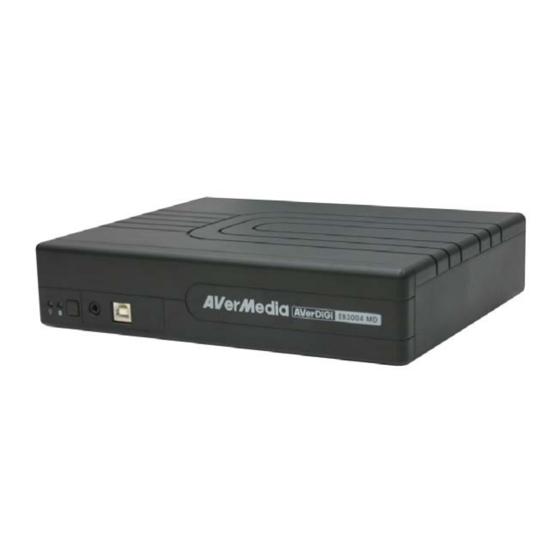
Chapter 1 Introduction Package Content (1) AVerDiGi EB3004 MD unit (2) Remote Control (batteries included) (3) Quick User Guide (4) Power Cord * The power cord varies depending on the standard power outlet of the country where it is sold. (5) Power Adapter (6) Internal HDD holder (8 screws are inculded) (7) Software CD (User Manual included) -
Page 6: Front Panel
Scheduled recording (00:00~23:00 set by hour ) Search for recorded video files by date/time/event Input/Output: 4 sensor inputs and 1 relay output control Audio In/Out: 4 audio in and 1 audio out Front Panel Name Function Light when the unit is power on (1) DVR Power LED Indicate the hard disk running state. -
Page 7: Setting Up The Dvr Unit
AVerMedia has expressly advised about the risk of such damages. The entire risk arising out of the use of any information attached here with is borne by the recipient. - Page 8 Secure the brackets on the hard disk Connect the the SATA cable and the power connector to the hard disk Secure the hard disk inside the unit then place Push the cover forward and secure the cover unit cover 7. You may now connect all the cables. When the power is connected, the Power LED light turns on...
-
Page 9: Connecting Devices
1.5.2 Connecting Devices The back panel of the DVR unit, user can connect up to 4 video cameras, 4 sensor devices, 1 alarm device and output video to a TV or CRT/LCD monitor. Connecting the unit to the PC, then use the bundled software enables user to transfer, playback and segment the video. -
Page 10: Connecting The Audio, Sensor And Relay Device
1.5.3 Connecting the Audio, Sensor and Relay device The Sensor, Alarm, and audio port enable you to connect 4 sensor inputs, 1 relay outputs, and 4 audio in and 1 audio out device. Just connect the external sensor, relay, and audio in/out device pin directly to the pinhole. - Page 11 Sensor in and Alarm pinhole: Pin # Definition Sensor 1 signal Sensor 1 Ground signal Sensor 2 signal Sensor 2 Ground signal Sensor 3 signal Sensor 3 Ground signal Sensor 4 signal Sensor 4 Ground signal Relay signal Relay signal RS-232 pinhole: Pin # Definition...
-
Page 12: Chapter 2 Operating The Dvr Unit
Chapter 2 Operating the DVR unit Familiarizing the Remote Control Buttons Use the Remote control to operate the OSD menu on surveillance screen. Button Function A functional key for multiple DVR system remote control Switch to Channel 1 As a number key for entering password Switch to Channel 2 As a number key for entering password Switch to Channel 3... - Page 13 Button Function To move the selection to the left and right (16) ▲ To go up and down and select the items in the menu list or change the settings ▼ ZOOM+ To zoom in view of PTZ camera (17) ZOOM- To zoom out view of PTZ camera PTZ camera control button.
-
Page 14: Using Ab Repeat Function
2.1.1 Using AB Repeat Function AB Repeat function allow user to set a video segment from A to B point and play on the surveillance screen until user stop. 1. Press (play button) to call out the SEARCH MODE menu to find the recorded video that user wants to playback. -
Page 15: Controlling Ptz Camera
2.1.2 Controlling PTZ Camera Using remote control, user can easily control PTZ camera at local site. Before starting, make sure the PTZ camera is connected with the DVR unit. And then, please go to OSD menu to enable PTZ control (see also 3.1 Menu Function: PTZ Setup). -
Page 16: To Set Preset Position
2.1.2.2 To Set Preset Position User can set 9 preset positions for PTZ camera. Using button to set the preset position. 1. Press and camera channel number button ( to enter PTZ mode. 2. Using to adjust the lens of the PTZ camera to the position that ▲... -
Page 17: Using The Dvr For The First Time
Using the DVR for the First Time 1. Make sure all devices and power cables are well connected. 2. Turn on the DVR unit by connecting the power cable into the power plug. 3. User should see the SYSTEM INITIALIZE windows appear on the surveillance screen. The system will do hard disk detection automatically. -
Page 18: Surveillance Screen
Surveillance Screen This chapter will describe the symbols on the surveillance screen and screen display mode. While DVR is playback, the record action will keep working and the surveillance screen will playback the recorded video. Surveillance Screen Preview Mode Symbol Description DVR is recording Audio is enabled... - Page 19 Playback Mode Symbol Description Playback the recorded video Audio is enabled AB segment is set and playing Recorded video is playback at backward speed(2x, 4x, 8x, 16x, 32x, or 64x) Recorded video is playback at faster forward speed(2x, 4x, 8x, 16x, 32x, or 64x) Always Recording Button Recording Motion Recording...
-
Page 20: Setup The Time Stamp
2.3.1 Setup the Time Stamp Current date and time could be displayed on each channel screen by enabling TIME STAMP function. Please follow the below steps to enable TIME STAMP. 1. Press to call out OSD menu. 2. Using move the highlight to CAMERA/RECORD and press ▲... -
Page 21: Playback The Video
Playback the Video If the unit is recording the video, you may have to stop video recording in order to do video playback. To stop video recording, press SEARCH METHOD 1. Press (play). TIME SEARCH FILE LIST SMART MOTION SEARCH 2. - Page 22 SMART MOTION SEARCH (search by motion event): SMART MOTION SEARCH START TIME: 2009 / 05 / 09 11:36:21 TIME: 2009 / 05 / 18 11:36:21 1. In SMART MOTION SEARCH window, the START TIME and END TIME show the date and time from when the SEARCH START TIME : 2009 / 05 / 09 11:36:21 SEARCH END...
-
Page 23: Chapter 3 Osd Navigation Tree
Chapter 3 OSD Navigation Tree The follow figure is an OSD menu tree map. To call out the OSD menu, press on the remote control. -
Page 25: Menu Function
Menu Function Use remote control to navigate in the OSD menu. The red frame turns yellow when you are making a selection. Each time you change the video display output or video system (NTSC/PAL), the power must be turned off and on to reset the DVR unit. OSD MENU Description CAMERA/RECORD SETUP... - Page 26 OSD MENU Description GENERAL SETUP WATERMARK RECORD MODE Enable/disable the recorded image authenticates protection. DVR NAME COMPANY TIME STAMP User can use ImageVerificiation application to identify the WATERMARK AUTO RECORD image that has been watermark protected. AUTO RECORD Enable/disable auto continue recording when interrupted (i.e., power breakdown, video playback or configuration setup).
- Page 27 OSD MENU Description CAMERA NAME SETUP CHANNEL NAME CAMERA1 CAMERA2 Give a name for the channel 1 ~ 4. Maximum is 12 characters CAMERA3 and can enter A~Z, 0~9, !, “, #, $, %, &, ‘, (, ), *, +, -, /, :, ;, <. CAMERA4 >, ?, @, and space.
- Page 28 OSD MENU Description MAIN MENU DISPLAY CAMERA/RECORD DISPLAY Configure the parameters of video and setting of spot monitor. SCHEDULE DISPLAY SETUP EVENT SETUP STORAGE COLOR ADJUSTMENT SYSTEM VIDEO OUT SETTING VIDEO SHIELD VGA - TV SELECTION MAIN - MAIN SPOT MONITOR QUAD EVENT TYPE ADJUSTABLE...
- Page 29 OSD MENU Description VIDEO OUT SETUP VIDEO SHIELD SHARPNESS Select the channel and set an area that will be blocking for COLOR ENHANCEMENT particular security issue when DVR unit is recording such as VGA MODE MODE1 RESOULTION SVGA enter password for entrance guard. DISPLAY SETUP VGA - TV SELECTION COLOR ADJUSTMENT...
- Page 30 OSD MENU Description MAIN MENU RECORD SCHEDULE CAMERA/RECORD By default, in 24 hours, the recording schedule is set to always DISPLAY SCHEDULE record every hour. Refer to the table below to customize the EVENT SETUP recording condition. STORAGE SYSTEM Condition Description ALWAYS Record non-stop.
- Page 31 OSD MENU Description MAIN MENU EVENT SETUP CAMERA/RECORD DISPLAY Configure alarm, sensor, and motion. SCHEDULE EVENT SETUP EVENT SETUP STORAGE ALARM SETTING SYSTEM SENSOR SETTING MOTION DETECTION ALARM SETTING Configure parameters of alarm. ALARM SETUP ALARM TYPE RECORD ALARM PERIOD 005 SEC ALARM CONTINUOUSLY SELECT / DESELECT ALL...
- Page 32 OSD MENU Description SENSOR SETUP SENSOR SENSOR1 SENSOR2 SENSOR3 SENSOR4 ENABLE Customize the initial state of the attached sensor. TYPE ENABLE Active/deactivate the sensor. TYPE Select the state of the sensor. NO: Indicates that the initial state of the sensor is normal open.
- Page 33 OSD MENU Description MAIN MENU STORAGE SETUP CAMERA/RECORD DISPLAY To format hard disk and enable/disable hard disk spaces SCHEDULE recycle. EVENT SETUP STORAGE STORAGE SETUP SYSTEM HDD OVERWRITE HDD SIZE 953 , 849MB HDD USED 279MB HDD FORMAT HDD OVERWRITE Enable/disable replacing the earliest recorded file when the hard disk space runs out.
- Page 34 OSD MENU Description STORAGE SETUP 4. After entering the last number, the “PASSWORD HDD OVERWRITE CORRECT” appears, you are now authorized to format the HDD SIZE 953 , 849MB hard disk. HDD USED 279MB HDD FORMAT 5. It is done when the “FORMAT DISK SUCCESS” appears. Formatting the hard disk will permanently delete all the recorded files.
- Page 35 OSD MENU Description SYSTEM SETUP DATE FORMAT SYSTEM INFO Select the display format of the date -- YYYY/MM/DD, DATE / TIME MM/DD/YYYY, or DD/MM/YYYY PASSWORD CHANGE AUDIO SETUP INSTANT PLAYBACK 060 SEC DATE LANGUAGE ENGLISH Set the current date TIME Set the current time Display the latest time synchronization date and time.
- Page 36 OSD MENU Description SYSTEM SETUP PASSWORD CHANGE SYSTEM INFO PASSWORD CHANGE SETUP DATE / TIME PASSWORD SETUP PASSWORD CHANGE ADMINISTRATOR AUDIO SETUP INSTANT PLAYBACK 060 SEC LANGUAGE ENGLISH Enable/disable full system password protection. This would prevent unauthorized user to stop video recording, change system settings and formatting the hard disk.
- Page 37 OSD MENU Description SYSTEM SETUP AUDIO SETUP SYSTEM INFO AUDIO SETUP DATE / TIME MUTE PASSWORD CHANGE AUDIO OUT @ QUAD AUDIO SETUP RESET TO DEFAULT INSTANT PLAYBACK 060 SEC LANGUAGE ENGLISH MUTE Enable/disable to hear audio sound while playback. To hear sound, make sure the unit is connected to a speaker.
-
Page 38: Chapter 4 Using The Usb Playback Console
Chapter 4 Using the USB Playback Console Recommended system requirements Pentium®4 2.4GHZ or above Windows®2000/ XP DDR 256 MB Graphic function must support DirectDraw Audio card or built-in Speaker 1 available USB2.0 port Installing the USB Playback Console To install the USB Playback Console: Place Installation CD into the CD-ROM drive. -
Page 39: Running The Usb Playback Console
Running the USB Playback Console To run the application, click the icon on the PC desktop Name Function Exit To close the application. (2) Progress bar Show the progress of the file being played. You may move the bar to seek at any location of the track. - Page 40 Name Function (4) Open File To select the video file source for playing. - DVR Recorded File (HD): To playback the recorded video from the hard disk which was recording video on the DVR system. (see aslo Chapter 4.3.2) - Backup File(.dvr): The file is backup and save in *.dvr file format. (see also Chapter 4.3.3)
-
Page 41: To Cut And Save The Portion Of The Recorded Video
Name Function (11) Event List Select the event you want to playback. The event list only available when user select to playback in DVR Recorded File(HD). (12) Camera ID Show the number of cameras that are being viewed. When you are in single screen mode, click the camera ID number to switch and view other camera. -
Page 42: Playback Dvr Recorded File From Hard Disk
4.3.2 Playback DVR Recorded File from Hard Disk Please have the hard disk which containing of recorded video data install on your PC or using external USB enclosure to connect to your PC. Click Open File button Select DVR Recorded File(HD) and click OK. Select the hard disk drive from Select Disk window and click OK. -
Page 43: Playback Backup File(*.Dvr)
4.3.3 Playback Backup File(*.dvr) Click Open File button. Select Backup File(*.dvr) and click OK. Locate the backup file folder and click OK. When open the backup video file, just locate the where backup file folder is. And then, Playback Date/Time Selection window appears. Select the date and time and click OK. -
Page 44: Backup Recorded Video File
Chapter 5 Backup Recorded Video File HDD Backup application provides user an interface to view recorded video from hard disk and backup it. Familiarizing with HDD Backup Application Name Function Date Select the date for events Hour and Channel User can select the hour and channel for events. : All events in this hour and channel have been selected. -
Page 45: To Backup Recorded Video File
Name Function Video display Display first frame of each recorded video channel from 4 selected. Show the progress of the event being played. User may move the bar to Progress bar seek at any location of the track Source Disk To select the hard disk drive (10) Target Path To locate on where user wants to save the file... - Page 46 Locate on where user wants to save the backup file 10. Click Start to process backup 11. To stop the backup progress, click Stop 12. To play the backup file, see 4.3.3.
-
Page 47: Chapter 6 Imageverification
Chapter 6 ImageVerification Image Verification is a watermark-checking program to identify the authenticity of a saved image (e.g. by snapshot). This program can only verify uncompressed bmp image files. To Run the ImageVerification To run the ImageVerification application, click the Watermark button on USB Playback Application main interface. -
Page 48: Chapter 7 Ienhance
Chapter 7 iEnhance The bundled iEnhance is a video editing tool and can only be used with *.dvr video file. It allows you to adjust the video picture quality, segment and save the selected portion of the video, zoom in and out the image, and print or save the screen shot. You can also save the setting and apply it on other files. -
Page 49: To Use Istable
Name Function (8) Full Screen Use the entire screen to only display the video. (9) Default Set the video back to original state and delete all the changes in the history box. (10) History Box List all the actions. (11) Undo Delete the last action. -
Page 50: Warranty Notice
Any other cause which does not relate to a product defect 3. Cartons, cases, batteries, cabinets, tapes, or accessories used with product 4. AVerMedia does not warrant that this product will meet your requirements; it is your responsibility to determine the suitability of this product for your purpose WHAT WE WILL AND WILL NOT PAY FOR We will pay labor and material expenses for covered items.
Need help?
Do you have a question about the AVerDiGi EB3004 MD and is the answer not in the manual?
Questions and answers