Table of Contents
Advertisement
Quick Links
Advertisement
Table of Contents

Related Manuals for Avermedia AVerDiGi EXR6004 Mini


Summary of Contents for Avermedia AVerDiGi EXR6004 Mini
- Page 1 ® AVerMedia AVerDiGi EXR6004 Mini User Manual Nov. 2009...
- Page 2 In no event will AVerMedia be liable for direct, indirect, special, incidental, or consequential damages arising out of the use or inability to use this product or documentation, even if advised of the possibility of such damages.
- Page 3 WARNING TO REDUCE RISK OF FIRE OR ELECTRIC SHOCK, DO NOT EXPOSE THIS APPLIANCE TO RAIN OR MOISTURE CAUTION IF THERE IS ANY DAMAGE, SHORTAGE OR INAPPROPRIATE ITEM IN THE PACKAGE, PLEASE CONTACT WITH YOUR LOCAL DEALER. WARRANTY VOID FOR ANY UNAUTHORIZED PRODUCT MODIFICATION NOTICE - INFORMATION IN THIS DOCUMENT IS SUBJECT TO CHANGE WITHOUT NOTICE.
-
Page 4: Table Of Contents
Table of Contents Chapter 1 Introduction ..................1 1.1 Package Content ......................2 1.2 Features ......................... 2 1.3 Front Panel ........................4 1.4 Back Panel ........................4 1.5 Setting Up the DVR Unit ....................5 1.5.1 Installing the Hard Disk ....................5 1.5.2 ... - Page 5 3.10 User Setup ........................43 Chapter 4 Using the USB Playback Console........... 45 4.1 Recommended system requirements ................45 4.2 Installing the USB Playback Console ................45 4.3 Running the USB Playback Console ................46 4.3.1 To Cut and Save the Portion of the Recorded Video ..........48 4.3.2 ...
- Page 6 Chapter 9 Web Tools ..................90 9.1 Dispatch Server ......................90 9.1.1 To Run Dispatch program: ..................90 9.2 Remote Setup ....................... 91 9.2.1 To Add DVR server ....................91 9.2.2 To Setup Remote System Setting ................92 9.2.2.1 ...
-
Page 7: Chapter 1 Introduction
Chapter 1 Introduction AVerDiGi EXR6004 Mini brings you the new version of pure NVR. With Compact size, it provides 4 channel video and audio inputs. Shattering marketing limitation by supporting full range of IP camera from all major manufactures worldwide and accepting H.264, MPEG4 and MJPEG video streaming format. -
Page 8: Package Content
Package Content (1) AVerDiGi EXR6004 Mini unit (2) Software CD (User Manual included) (3) Quick User Guide (4) Power Cord * The power cord varies depending on the standard power outlet of the country where it is sold. (5) Power Adapter... - Page 9 Optimized de-interlace options for dynamic or static camera scenes Recording VGA Recording frame rate: 120/100 fps (NTSC/PAL) Recording modes: continuous/ smart/ motion/ alarm/ manual recording All recording modes can be triggered by schedule Easy snapshot in preview and playback screen Support pre-recording up to 10 seconds Search &...
-
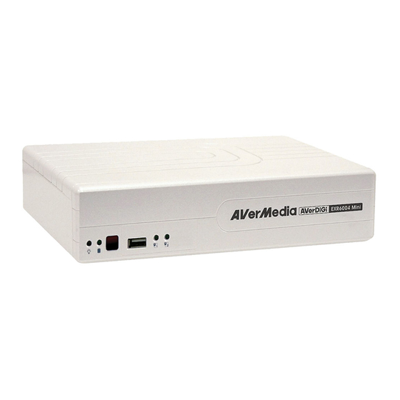
Page 10: Front Panel
Front Panel Name Function Light when the unit is power on (1) DVR Power LED Indicate the hard disk running state. Light when the HDD is running (Read/Write) (2) HDD LED (3) IR Sensor Receive signal from the remote control to operate the unit (4) USB 2.0 Port For pen drive/DVD-ROM connection (5) Network 1 Indicator... -
Page 11: Setting Up The Dvr Unit
AVerMedia has expressly advised about the risk of such damages. The entire risk arising out of the use of any information attached here with is borne by the recipient. - Page 12 Secure the hard disk inside the unit then place unit Push the cover forward and secure the cover cover 7. You may now connect all the cables. When the power is connected, the Power LED light turns on...
-
Page 13: Connecting Devices
1.5.2 Connecting Devices The back panel of the DVR unit, user can connect the 4 sensor devices, 1 alarm device, audio input/output device and an external HDD storage device. Through the two Gigabit LAN ports can connect with the IP cameras and allows user to remote access the DVR server. The USB ports can connect the mouse and keyboard for more easily to operate DVR server. -
Page 14: Connecting The Audio, Sensor And Relay Device
1.5.3 Connecting the Audio, Sensor and Relay device The Sensor, Alarm, and audio port enable you to connect 4 sensor inputs, 1 relay outputs, and 1 audio in and 1 audio out device. Just connect the external sensor, relay, and audio in/out device pin directly to the pinhole. -
Page 15: Chapter 2 Operating The Dvr Unit
Chapter 2 Operating the DVR unit First Time Using the DVR Unit 1. Connect the mouse to the USB port located at front panel of the DVR unit. 2. Using the mouse and virtual keyboard (see also Chapter 2.1.1) to operate the DVR system. 3. -
Page 16: Using The Virtual Keyboard
2.1.1 Using the Virtual Keyboard User can use the Virtual Keyboard when the keyboard is not available. Just click or right-click screen to call out the virtual keyboard. For uppercase, click Caps button. To exit, click Esc. -
Page 17: Familiarizing The Buttons In Preview Mode
Familiarizing the Buttons in Preview Mode Name Function Call up the Logout dialog box. (1) Exit In the logout dialog box, you may do the following: Reboot: To restart the DVR system. It is required to enter the password Power Off: To shutdown the DVR system. Login: Using different ID to login to DVR system. -
Page 18: Setting Up And Using The Emap
Name Function View in full screen. To return, press the right button of the mouse or ESC on the (15) Full screen keyboard or click the arrow icon. Click to exit from full screen mode When you switch to full screen in multiple-screen mode, Left click to toggle to only display one of the video in the multiple-screen mode or all. -
Page 19: To Use The Emap
2.2.1.2 To Use the Emap 1. Click E-map. 2. In the Emap screen, click the camera icon to switch on the area where the camera is located on the map and to display the video at the upper right corner of the Emap screen. At the lower right corner of the Emap screen, it lists all the warning message. -
Page 20: Familiarizing The Buttons In Ptz Camera Controller
2.2.2 Familiarizing the Buttons in PTZ Camera Controller (11) (10) Name Function (1) Close Exit PTZ camera controller. (2) Setup Configure PTZ cameras.(see also Chapter 2.2.2.1) (3) AutoPan Operate the PTZ cameras automatically based on the selected camera group preset position number. -
Page 21: Using Event Log Viewer
5. Select the Preset Number to assign a number for the PTZ camera current position. And then, click Save to save the setting. 6. Set the DwellTime for how long the PTZ camera stays in that position before it moves to the next one. -
Page 22: To Playback The Recorded Video
To Playback the Recorded Video To switch in Playback mode, click Playback button at the lower right corner of Preview mode user interface Name Function (1) Split Screen Select from 2 different split screen type to playback the recorded video file of all the Mode camera or one camera on a single screen. - Page 23 Name Function (5) Date Select the date on the calendar and the time from 00 to 23 to where to start playing the recorded video file. The numbers from 00 to 23 represent the time in 24-hour clock. The numbers from 01 to 04 represent the camera ID.
-
Page 24: To Cut And Save The Wanted Portion Of The Recorded Video
Name Function (15) Find Next Search for the next event or changes in the motion detector frame. You can use this when you are using Event Search function. (16) Event Search Search from the recorded activities that were recorded in event log (i.e., Sensor, Motion, Video Loss)(see also Chapter 2.3.3) -
Page 25: Using The Event Search
2.3.3 Using the Event Search 1. Click on the video screen on where you want to search. 2. Click Event Search. The Event Search Setting dialog box would appear on the screen. 3. In the Event Search Setting dialog box, check the type of condition you want to search. Then, click OK to start searching. -
Page 26: Chapter 3 Customizing The Dvr System
Chapter 3 Customizing the DVR System In the Preview screen mode, click button to customize your DVR. Enter the ID and password to authenticate(Default ID is superuser and password is 111111). When the DVR configuration setup selection appears, select and click the buttons you want to change the setting. - Page 27 (4) Overwrite Enable When there is not enough free space to record one hour data, the system automatically replaces the oldest data. (5) Language Customize the system to display the tool tips and dialogs based on the selected language. Default language is in English.
- Page 28 Set the time gap of the Auto Scan function from 3 to 10 seconds. This automatically switches to the next video in cycle depending on the set time gap. (9) Login Enable the conditions in Login section you want the system to automatically carry out. Auto Login after system boot up Execute the DVR when the operating system is started.
-
Page 29: Camera Setup
Camera Setup Click Default will back to the factory default value. 3.2.1 To Setup the IP Camera (1) Camera Icons Select the camera number you want to view. To enable/disable all cameras, click ALL check box. (2) Enable Set to enable/disable the selected camera. When there is no video source on the camera, we suggest disabling it so that the system won’t detect it as video loss error. - Page 30 Click the radio button of Protocol to start setup IP camera. Select the Protocol, Model, Video Format, and Channel of the IP camera. Enter IP address and connecting port in IP Camera Site column. Also, user can enter URL of IP camera instead of IP address. If the IP camera has authority request, please enable Authentication and enter ID and Password.
- Page 31 4. The system automatically detects the camera and input relates information. In the Content section, enter sensor Description. 5. In the test section, click Test to check the sensor status. Red is high and Green is low. 6. Click OK to exit and accept the setting and Cancel to exit without saving the setting. Relay Setting Click Relay button.
-
Page 32: To Setup Camera From The Remote Dvr
3.2.2 To Setup Camera from the Remote DVR User can add the camera from another DVR through the network. (1) Camera Icons Select the camera number you want to view. To enable/disable all cameras, click ALL check box. (2) Enable Set to enable/disable the selected camera. -
Page 33: Recording Setup
- Connect Click to connect the camera when all configurations are set. Recording Setup (1) Camera Icons Select the camera number you want to set the recording setting. To select all the cameras, enable the ALL check box. To select more than one camera, Right click on the camera icon. To select one camera only, Left click on the camera icon. -
Page 34: Network Setup
Network Setup Click Default will back to the factory default value. (1) Server Name Assign a name for the DVR unit. Alphabet letters and numbers only. (2) Transmitting Cameras Select and click on the camera number in the Transmitting Camera section you want to make it accessible via internet using WebViewer, Remote Console, CM3000(Gold),PDA Viewer and JAVAViewer (still image). - Page 35 IP: Assign a constant IP address which a real IP address gives from ISP to DVR system. Mask: It is a bitmask used to identify the sub network and how many bits provide room for host addresses. Enter the subnet mask of the IP address which user has assigned to DVR system. Gateway: A network device acts as a passageway to internet.
- Page 36 Network Bandwidth Limit By Channel: Set the network bandwidth by each channel. All: Set the total network bandwidth consumption limit.
-
Page 37: Schedule Setting
Schedule Setting Schedule to record, enable network, reboot and disable alarm of all the cameras either weekly or one time. The number from 00 to 23 represent the time in 24-hour clock. The left most column display the days in a week. -
Page 38: Backup Setup
Backup Setup In the Backup Setting dialog box, the number from 00 to 23 represent the time in 24-hour clock. The numbers from 01 to 04 represent the camera number. When you back up the file, you may find Qplayer application included in the backup folder. -
Page 39: Using Qplayer To Playback Backup Video
3.6.1 Using QPlayer to Playback Backup Video You can playback the backup files using QPlayer applications on the PC. When you back up the recorded file, QPlayer applications are automatically included in the backup folder. With QPlayer, it is the same as in Playback mode and supports different split screen types to view all the video at the same time. - Page 40 Name Function (6) Archive Select the date on the calendar and the time from 00 to 23 to where to start playing the recorded video file. – OPEN FILE: user can open the recorded file from HDD – Day Light Saving: the playback calendar will show the available video records during day light saving time period.
- Page 41 Name Function (18) Watermark To verify the playback video has not been modified To verify the playback video doesn’t been modified. Click to check the video. Watermark verification window will show up as following:...
-
Page 42: To Cut And Save The Portion Of The Recorded Video
3.6.2 To Cut and Save the Portion of the Recorded Video Use the Playback Control buttons or drag the bar on the playback progress bar and pause on where you want to start the cut. Then, click Segment to set the begin mark. Use the Playback Control buttons or drag the bar on the playback progress bar and pause on where you want to end the cut. -
Page 43: Sensor Setting
Sensor Setting The I/O device must be installed to use this function. 1. The system automatically detects the I/O device that has connected with DVR system and display on the drop-down list column. Click the drop-down list and select the sensor that user wants to configure. 2. -
Page 44: Relay Setting
Relay Setting The I/O device must be installed to use this function. 1. The system automatically detects the I/O device that has connected with DVR system and display on the drop-down list column. 2. Enter sensor name in Name column. 3. -
Page 45: Alarm Setting
Alarm Setting In the Alarm Setting dialog box, click Add to insert and set new alarm setting, click Delete to remove the selected alarm setting, click OK to exit and save the setting, Cancel to exit without saving. Click Default will back to factory default value. - Page 46 Reboot: when the DVR system reboot without abnormal condition, the system will send out the alarm message. Abnormal Reboot: when the DVR system reboot in irregular condition, the system will send out the alarm message. Recording is switched off: when the recording has been stopped, the system will send out the alarm message.
- Page 47 - Relay Output Set to enable/disable the relay operation when the alarm is activated and to extend additional time in second before it stops the relay operation. 1. Next to the Relay Output check box, click Detail. 2. In the Alarm Relay dialog box, select from the available relay list and in the ON column, set to enable/disable the relay operation when the alarm is activated.
- Page 48 Start Recording Record the video from the selected camera. 1. Next to the Start Recording check box, click Detail. 2. In the Alarm Recording Setting dialog box, select the camera to enable/disable video recording. Enable All to select all cameras. 3.
-
Page 49: User Setup
User Setup 3.10 Only administrator level authority can access User Setting. The maximum user accounts are 32. In the User Setting dialog box, click Add to insert a new user, Delete to remove the selected user, Edit to modify the user control right, OK to exit and accept the setting, and Cancel to exit without saving the setting. - Page 50 using internet explorer. Remote Console Allow the user to remote modify DVR system setting. Remote LogViewer Allow the user to view the event log from remote site. IP Camera Enable/disable user to add new IP camera when using the Web Viewer. Remote Access Time Enable Infinite check box to access DVR without time limit.
-
Page 51: Chapter 4 Using The Usb Playback Console
Chapter 4 Using the USB Playback Console Recommended system requirements Pentium®4 2.4GHZ or above Windows®2000/ XP DDR 256 MB Graphic function must support DirectDraw Audio card or built-in Speaker 1 available USB2.0 port Installing the USB Playback Console To install the USB Playback Console: Place Installation CD into the CD-ROM drive. -
Page 52: Running The Usb Playback Console
Running the USB Playback Console To run the application, click the icon on the PC desktop Name Function Exit To close the application. (2) Progress bar Show the progress of the file being played. You may move the bar to seek at any location of the track. - Page 53 Name Function (4) Open File To select the video file source for playing. - DVR Recorded File (HD): To playback the recorded video from the hard disk which was recording video on the DVR system. (see aslo Chapter 4.3.2) - Backup File(.dvr): The file is backup and save in *.dvr file format. (see also Chapter 4.3.3) - Backup File (.avf): The file is backup and save to external USB storage device...
-
Page 54: To Cut And Save The Portion Of The Recorded Video
Name Function (15) Split Screen Mode Select from different screen view to playback the recorded video file of the entire camera or one camera on screen. 4.3.1 To Cut and Save the Portion of the Recorded Video Use the Playback Control buttons or drag the bar on the playback progress bar and pause on where you want to start the cut. -
Page 55: Playback Backup File(*.Dvr)
4.3.3 Playback Backup File(*.dvr) Click Open File button. Select Backup File(*.dvr) and click OK. Locate the backup file folder and click OK. When open the backup video file, just locate the folder of backup file And then, Playback Date/Time Selection window appears. Select the date and time and click OK. -
Page 56: To Backup Recorded File
4.3.4 To Backup Recorded File HDD backup function allows user to backup recorded file from hard disk. Click Adv. Function → HDD Backup on USB Playback Console UI. Select the source hard disk. In Backup date/time selection window, select the date and time. 00-24 represents hours and 01-04 represents channels. -
Page 57: Chapter 5 Imageverification
Chapter 5 ImageVerification Image Verification is a watermark-checking program to identify the authenticity of a saved image (e.g. by snapshot). This program can only verify uncompressed bmp image files. To Run the ImageVerification To run the ImageVerification application, click the Watermark button on USB Playback Application main interface. -
Page 58: Chapter 6 Ienhance
Chapter 6 iEnhance The bundled iEnhance is a video editing tool and can only be used with *.dvr video file. It allows you to adjust the video picture quality, segment and save the selected portion of the video, zoom in and out the image, and print or save the screen shot. You can also save the setting and apply it on other files. -
Page 59: To Use Istable
Name Function (12) Noise Reduce Adjust the softness and repair the damaged colours. (13) Sharpness Improve the overall image by enhancing edges. This gives the image more depth. (14) Effects Gray Scale: convert the image into black and white (monochrome). Normalize: adjust the brightness intensity. -
Page 60: Chapter 7 Using The Remote Programs
Chapter 7 Using the Remote Programs User can use Microsoft Internet Explorer to access DVR system by entering the IP address. To use this feature, make sure that your PC and DVR server both are connected to the internet and the Network feature is enabled. -
Page 61: Familiarizing The Buttons In Webviewer
Familiarizing the Buttons in WebViewer Right-clicking on the WebViewer video screen, enables you to start video recording, change video quality, switch camera and enable/disable DirectDraw. Name Function (1) DirectDraw Enhance the video quality. Not all graphic cards can support this function. If you cannot see the screen display correctly or screen is messed, please check with VGA card vendor. - Page 62 Name Function (14) Select cameras Select to the view camera from different server. In Select Camera dialog box, Display to view column, click to enable/disable viewing the camera. Click Add Server and select the server type between DVR and IP Cam to add. Click Delete Server to delete the selected item.
-
Page 63: To Setup Remote System Setting
7.1.1 To Setup Remote System Setting The setting here applies to Remote DVR only. Click the selection to configure. 7.1.1.1 System Setting In the System Setting window, click Update to accept the new settings, click Exit to exit without saving, and click Default to revert back to original factory setting. -
Page 64: 7.1.1.2 Camera Setting
- Auto Scan Period Set the time gap of the Auto Scan function from 3 to 10 seconds. This automatically switches to the next video in cycle depending on the set time gap. (5) Login Enable the conditions in Login section you want the system to automatically carry out. - Auto Record after system boot up Automatically start video recording when the DVR is executed. - Page 65 Enable/disable audio of the camera. - Name Change the camera name - Description Add a short comment (5) IP Camera Information Click IP Setting to setup the parameters of the IP camera. 1. Select the Protocol, Model, Video Format, and Channel of the IP camera. 2.
- Page 66 Remote DVR Camera Setting Select the camera to modify settings. In the Camera Setting window, click Update to save and apply the new settings, click Exit to exit without saving. (1) Camera Icons Select the camera number you want to view. To enable/disable all cameras, click ALL check box. (2) Enable Set to enable/disable the selected camera.
-
Page 67: 7.1.1.3 Record Setting
7.1.1.3 Record Setting In the Recording setup window, click OK to accept the new settings, click Exit to exit without saving, and click Default to revert back to original factory setting. (1) Camera Icons Select the camera number you want to set the recording setting. To select all the cameras, enable the ALL check box. - Page 68 Smart Recording Automatically switch to recorded at the maximum frame rate setting once a motion is detected and if there is no motion, it records at the minimum frame rate setting. - No Recording The system won’t do any recording. (3) Motion Detection Adjust the sensitivity of the motion detection.
-
Page 69: 7.1.1.4 Network Setting
7.1.1.4 Network Setting In the Network Setting dialog box, click Update to accept the new settings, click Exit to exit without saving, and click Default to revert back to original factory setting. For the network service ports that use by DVR server, please see Appendix (1) Server Name... - Page 70 Network Bandwidth Limit By Channel: Set the network bandwidth by each channel. All: Set the total network bandwidth consumption limit.
-
Page 71: 7.1.1.5 Alarm Setting
7.1.1.5 Alarm Setting In the Alarm Setting dialog box, click Add to insert and set new alarm setting, click Delete to remove the selected alarm setting, click Update to save the setting, Exit to exit without saving, and Default to revert back to original factory setting. - Page 72 Reboot: when the DVR system reboot without abnormal condition, the system will send out the alarm message. Abnormal Reboot: when the DVR system reboot in irregular condition, the system will send out the alarm message. Recording is switched off: when the recording has been stopped, the system will send out the alarm message.
- Page 73 - Send E-mail Send an electronic text message. Next to the Send Email check box, click Detail. In the E-mail Setting dialog box, click OK to exit and save the setting and Cancel to exit without saving the setting. (1) Mail Server Enter the SMTP Server and port.
- Page 74 - PTZ preset point - Position the PTZ camera based on the preset point setting. Next to the PTZ preset point check box, click Detail. In the Trigger PTZ Preset Setting dialog box, select the PTZ camera number then select the Enable check box. Select the position of the PTZ camera when the alarm is activated and ended.
-
Page 75: Familiarizing The Buttons In Webviewer Ptz
Familiarizing the Buttons in WebViewer PTZ Name Function (1) Direction buttons Adjust and position the focal point of the PTZ camera. Click the center to pan automatically. (2) Zoom +/- Zoom in and out the image. (3) Select PTZ Choose to enable/disable the PTZ camera. In the Select PTZ dialog box, Select column, click to enable/disable viewing and controlling the PTZ camera. -
Page 76: Familiarizing The Buttons In Remote Console
Familiarizing the Buttons in Remote Console Name Function (1) Exit Close the Remote Console. (2) Split Screen Select from 1 or 4-split screen type to playback the recorded video file. Mode (3) Record Start/stop video recording. (4) Network Enable/disable remote system access. This feature allows you to access DVR server from a remote location via internet connection. -
Page 77: To Setup Remote Console Setting
7.3.1 To Setup Remote Console Setting Click Setup button to call out the System Setting window. Click OK to exit and save the setting and Cancel to exit without saving the setting. (1) Storage Path Set the directory on where to save the data. When there is not enough free space to record one hour data, the system automatically replaces the oldest data. -
Page 78: 7.3.2 Familiarizing The Buttons In Ptz Camera Controller
7.3.2 Familiarizing the Buttons in PTZ Camera Controller (11) (10) Name Function (1) Close Exit PTZ camera controller. (2) Setup Configure PTZ cameras. (3) AutoPan Operate the PTZ cameras automatically based on the selected camera group preset position number. (4) Focus +/- Adjust the focus manually to produce clear image. -
Page 79: Using The Remote Playback
Using the Remote Playback To use this feature, first you need to select the source of the file. In the Select Playback Mode dialog box, choose Local Playback to open the file that is recorded in the Remote Console, and Remote Playback to open the file that is recorded in the DVR server. -
Page 80: 7.4.1 Familiarizing The Buttons In Local Playback
7.4.1 Familiarizing the Buttons in Local Playback Name Function Select from 1 or 4-split screen type to playback the recorded video. (1) Split Screen Mode To close the application (2) Exit (3) Progress bar Show the progress of the file being played. You may move the bar to seek at any location of the track. - Page 81 Name Function (5) Playback Control Begin: Move at the beginning of the recorded video file. Buttons Previous: Go back to the previous frame. Slower: Play the recorded video file at the speed of 1/2x, 1/4x, 1/8x, 1/16x, or 1/32x. Rewind: Wind back the recorded video file. Pause: Briefly stop playing the recorded video file.
-
Page 82: To Cut And Save The Wanted Portion Of The Recorded Video
Name Function (13) Full screen View in Playback-compact mode. To return, press the right button of the mouse or ESC on the keyboard. (14) Event Log Show the record of activities that take place in the system (15) Find Next Search for the next event. -
Page 83: Familiarizing The Buttons In Realtime Playback
7.4.2 Familiarizing the Buttons in RealTime Playback Name Function (1) Split Screen Mode Select 1 or 4-split screen type to playback the recorded video file. (2) Exit To close the application (3) Progress bar Show the progress of the file being played. You may move the bar to seek at any location of the track. - Page 84 Name Function (6) Archive Select the date on the calendar and the time from 00 to 23 to where to start playing the recorded video file. – OPEN FILE: Click to open the recorded file from certain location. – Channel 01~ 16 & Channel 17 ~ 32: Click to switch to different channel group of playback calendar if the DVR supports more than 16 channels.
-
Page 85: Familiarizing The Buttons In Download And Playback
7.4.3 Familiarizing the Buttons in Download and Playback Name Function (1) Exit To close the application. (2) Progress bar Show the progress of the file being played. You may move the bar to seek at any location of the track. (3) Hour Buttons Select and click to playback the recorded video file on the specific time frame. - Page 86 Name Function (12) Audio Enable/disable volume (13) De-interlace To enhance the video quality. Set the de-interlace mode to #1, if you are capturing motionless picture and #2, if it captures lots of movement. (14) Watermark To verify the playback video has not been modified To verify the playback video doesn’t been modified.
-
Page 87: Using Handyviewer To Access Dvr Server
Chapter 8 Using HandyViewer to Access DVR Server Users can use a mobile phone to access the DVR through Internet. Make sure your mobile phone support IE browser and is connected to the internet. To access the DVR server, open IE browser and enter http://enter server IP or domain name here/mobile. -
Page 88: To Install Pdaviewer From The Internet
4. When you are prompted, click Yes to install the application using the default directory. 5. When done, click OK. 8.1.2 To install PDAViewer from the Internet Make sure you are connected to the internet. 1. Open the web browser and enter the server IP. Then click the hyperlink Download PDAViewer. -
Page 89: To Use The Pdaviewer
8.1.3 To Use the PDAViewer 1. Run the PDAViewer in the Programs. 2. Familiarizing the PDAViewer buttons. (10) Name Function (1) Connect Hook up to the DVR server. Make sure you are connected to internet. When the iView screen appears, click Add to add DVR server. Enter the server IP, port, user ID, password and select the connection type. -
Page 90: To Playback In Pdaviewer
3. To change the video quality, enable/disable audio, and select to display different camera, tap on the video screen longer the popup menu will appear. 8.1.4 To Playback in PDAViewer Run the PDAViewer in the Programs. Hook up to the DVR server. Click Connect icon and select the DVR server Click Playback to enter playback option screen Select the camera, data, and time... -
Page 91: Using Javaviewer To Access Dvr Server
11. User can change the relay status. Select the relay and tap on video screen longer the pop up menu will appear, and then, select the status (ON, OFF, Tigger) Using JavaViewer to Access DVR Server Using the mobile phone within Symbian Smart Phone OS to access the DVR through Internet. Make sure your mobile phone supports Symbian Smart Phone OS and can be connected to the internet. -
Page 92: To Use The Javaviewer
8.2.2 To Use the JavaViewer 1. Run the JavaViewer program. 2. Enter the DVR IP address, port number, user ID, and password. Please refer to your DVR server setting for that information. 3. And then, select the Connect to connect to DVR server. 4. -
Page 93: Using Iphone To Access Remote Dvr Server
Using iPhone to Access Remote DVR Server Using the iPhone can connect to remote DVR server through the Internet to view the live image. 8.3.1 Download the iViewer To use this feature, it is required to download the iViewer application to your iPhone. There are 2 ways to download the iViewer to your iPhone. -
Page 94: Using The Iviewer
II. Using iPhone to Download 1. Please make sure your iPhone connect to the Internet. 2. Select App Store from iPhone main screen. 3. Select Search and enter the keyword “AVerDiGi” to search. 4. In search result list, select the AVerDiGi iViewer. User will see a brief introduction of the AVerDiGi iViewer. - Page 95 3. After login, user should see the live video on iPhone screen. Display the camera number or information 4. Click the channel number (1 ~ 32) can switch to view each channel. 5. Click < or > to go back last page or next page of channels. 6.
-
Page 96: Chapter 9 Web Tools
Chapter 9 Web Tools The bundled Web Tools includes Dispatch Server , Remote Backup, and Remote Setup program. To install Web Tools, place the CD into the CD-ROM drive then click Install Web Tool. Dispatch Server Dispatch is designed to reduce the network traffic of the DVR server. Instead of connecting directly to the DVR server, the client can connect to the computer that is connected to the DVR server using the Dispatch program. -
Page 97: Remote Setup
Remote Setup Remote Setup is a tool for configuring DVR server from remote site. To install Remote Setup application, insert the Installation CD into CD-ROM drive and click Install Web Tool. After installation, click start the Remote Setup application. 9.2.1 To Add DVR server User need to add a DVR server and make connection in order to setup remote DVR server. -
Page 98: To Setup Remote System Setting
6. When connection is lost, click Reconnect to connect again. 7. To modify or delete the added DVR server, select the DVR server from listing and click Modify to change the setting and click Delete to remove the DVR server. User also can import the setting by clicking Import button. -
Page 99: Camera Setting
- Auto Scan Period Set the time gap of the Auto Scan function from 3 to 10 seconds. This automatically switches to the next video in cycle depending on the set time gap. (5) Login Enable the conditions in Login section you want the system to automatically carry out. - Auto Record after system boot up Automatically start video recording when the DVR is executed. - Page 100 Enable/disable audio of the camera. - Name Change the camera name - Description Add a short comment (5) IP Camera Information Click IP Setting to setup the parameters of the IP camera. 1. Select the Protocol, Model, Video Format, and Channel of the IP camera. 2.
- Page 101 Remote DVR Camera Setting Select the camera to modify settings. In the Camera Setting window, click Update to save and apply the new settings, click Exit to exit without saving. (1) Camera Icons Select the camera number you want to view. To enable/disable all cameras, click ALL check box. (2) Enable Set to enable/disable the selected camera.
-
Page 102: Record Setting
9.2.2.3 Record Setting In the Recording setup window, click OK to accept the new settings, click Exit to exit without saving, and click Default to revert back to original factory setting. (1) Camera Icons Select the camera number you want to set the recording setting. To select all the cameras, enable the ALL check box. - Page 103 Smart Recording Automatically switch to recorded at the maximum frame rate setting once a motion is detected and if there is no motion, it records at the minimum frame rate setting. - No Recording The system won’t do any recording. (3) Motion Detection Adjust the sensitivity of the motion detection.
-
Page 104: Network Setting
9.2.2.4 Network Setting In the Network Setting dialog box, click Update to accept the new settings, click Exit to exit without saving, and click Default to revert back to original factory setting. For the network service ports that use by DVR server, please see Appendix (1) Server Name... - Page 105 Network Bandwidth Limit By Channel: Set the network bandwidth by each channel. All: Set the total network bandwidth consumption limit.
-
Page 106: Alarm Setting
9.2.2.5 Alarm Setting In the Alarm Setting dialog box, click Add to insert and set new alarm setting, click Delete to remove the selected alarm setting, click Update to save the setting, Exit to exit without saving, and Default to revert back to original factory setting. - Page 107 Reboot: when the DVR system reboot without abnormal condition, the system will send out the alarm message. Abnormal Reboot: when the DVR system reboot in irregular condition, the system will send out the alarm message. Recording is switched off: when the recording has been stopped, the system will send out the alarm message.
- Page 108 - Send E-mail Send an electronic text message. Next to the Send Email check box, click Detail. In the E-mail Setting dialog box, click OK to exit and save the setting and Cancel to exit without saving the setting. (1) Mail Server Enter the SMTP Server and port.
- Page 109 - PTZ preset point - Position the PTZ camera based on the preset point setting. Next to the PTZ preset point check box, click Detail. In the Trigger PTZ Preset Setting dialog box, select the PTZ camera number then select the Enable check box. Select the position of the PTZ camera when the alarm is activated and ended.
-
Page 110: Remote Backup
Remote Backup Remote Backup is purely for backing up the *.dvr file from the DVR sever. You can select between Auto Backup and Manual Backup. Auto Backup continuously archives one hour of the recorded data at a time, starting from the specified date. As for Manual Backup, it only archives the recorded data of selected date. To back up the data, you must have at least 2G hard disk space. - Page 111 - Enable/disable Disk Recycle check box, to automatically overwrite the oldest file when there is not enough free space to backup the file. Manual Backup mode: the backup progress will start when user press the backup button - Click File Select to choose the date, time and camera you want to back up. - Click Browse to set the storage path.
-
Page 112: Appendix A Registering Domain Name
Appendix A Registering Domain Name DDNS (Dynamic Domain Name Service) is a data query service mainly used on the Internet for translating domain names into Internet addresses. It allows remote clients to intelligently search dynamic servers without any previous enquiring for servers’ Internet addresses. In order to take advantage of this intelligent service, first register your domain name on the following Web site http://ddns.avers.com.tw User Login... -
Page 113: Appendix B Specifications
Appendix B Specifications Operating system Embedded Linux Camera Inputs (IP) Video Streaming Format H.264/MPEG4/ MJPEG IP Recording Resolution Each individual channel can support a maximum of 2.3 Megapixels Display Frame Rate CIF:120/100 fps ; D1: 60/50 fps (NTSC/ PAL) Recording Frame Rate CIF: 120/100 fps ;... -
Page 114: Warranty Notice
Any other cause which does not relate to a product defect 3. Cartons, cases, batteries, cabinets, tapes, or accessories used with product 4. AVerMedia does not warrant that this product will meet your requirements; it is your responsibility to determine the suitability of this product for your purpose WHAT WE WILL AND WILL NOT PAY FOR We will pay labor and material expenses for covered items.
Need help?
Do you have a question about the AVerDiGi EXR6004 Mini and is the answer not in the manual?
Questions and answers