Table of Contents
Advertisement
Quick Links
Advertisement
Table of Contents

Related Manuals for Supero SUPERSERVER 6027R-73DARF


Summary of Contents for Supero SUPERSERVER 6027R-73DARF
- Page 1 UPER ® UPER ERVER 6027R-73DARF USER’S MANUAL...
- Page 2 The information in this User’s Manual has been carefully reviewed and is believed to be accurate. The vendor assumes no responsibility for any inaccuracies that may be contained in this document, makes no commitment to update or to keep current the information in this manual, or to notify any person or organization of the updates.
- Page 3 About This Manual This manual is written for professional system integrators and PC technicians. It provides information for the installation and use of the SuperServer 6027R-73DARF. Installation and maintainance should be performed by experienced technicians only. The SuperServer 6027R-73DARF is a high-end server based on the SC825TQ- R740LPB 2U rackmountable chassis and the X9DRD-7LN4F dual processor serverboard.
- Page 4 UPER ERVER 6027R-73DARF User's Manual Chapter 5: Advanced Serverboard Setup Chapter 5 provides detailed information on the X9DRD-7LN4F serverboard, in- cluding the locations and functions of connections, headers and jumpers. Refer to this chapter when adding or removing processors or main memory and when reconfi...
- Page 5 Preface Notes...
-
Page 6: Table Of Contents
UPER ERVER 6027R-73DARF User's Manual Table of Contents Chapter 1 Introduction Overview ......................1-1 Serverboard Features ..................1-2 Processors ...................... 1-2 Memory ......................1-2 SAS ......................... 1-2 Serial ATA ......................1-2 PCI Expansion Slots ..................1-2 Rear I/O Ports ....................1-3 Server Chassis Features ................ - Page 7 Table of Contents Control Panel LEDs ..................3-2 Power Fail ....................... 3-2 Information LED ....................3-2 NIC1 ........................ 3-2 NIC2 ........................ 3-2 HDD ......................... 3-3 Power ......................3-3 Drive Carrier LEDs ..................3-3 Chapter 4 System Safety Electrical Safety Precautions ................4-1 General Safety Precautions ................
- Page 8 UPER ERVER 6027R-73DARF User's Manual Chapter 6 Advanced Chassis Setup Static-Sensitive Devices .................. 6-1 Precautions ..................... 6-1 Unpacking ....................... 6-1 Control Panel ....................6-2 System Fans ....................6-3 System Fan Failure ..................6-3 Replacing System Fans .................. 6-3 Drive Bay Installation/Removal ............... 6-4 Accessing the Drive Bays ................
-
Page 9: Chapter 1 Introduction
Chapter 1 Introduction Overview The SuperServer 6027R-73DARF is a high-end server comprised of two main subsystems: the SC825TQ-R740LPB 2U chassis and the X9DRD-7LN4F dual processor serverboard. Please refer to our web site for information on operating systems that have been certifi ed for use with the system (www.supermicro.com). -
Page 10: Serverboard Features
ERVER 6027R-73DARF User's Manual Serverboard Features The SuperServer 6027R-73DARF is built around the X9DRD-7LN4F, a dual proces- sor serverboard based on the Intel C602J chipset and designed to provide maximum performance. Below are the main features of the X9DRD-7LN4F. (See Figure 1-1 for a block diagram of the chipset). -
Page 11: Rear I/O Ports
Chapter 1: Introduction Rear I/O Ports The color-coded I/O ports include one COM port, a VGA port, four USB 2.0 ports (additional USB headers are included on the serverboard) and four 1 Gb Ethernet ports. A dedicated IPMI LAN port is also included. Server Chassis Features The SC825TQ-R740LPB is an ATX form factor chassis designed to be used in a 2U rackmount confi... - Page 12 UPER ERVER 6027R-73DARF User's Manual Figure 1-1. Intel C602J Chipset: System Block Diagram Note: This is a general block diagram. Please see Chapter 5 for details. (AB) (AB) (CD) CPU REAR Socket 01 PROCESSOR SANDYBRIDGE CPU FRONT Socket 00 PROCESSOR SANDYBRIDGE (AB) (AB)
-
Page 13: Contacting Supermicro
Chapter 1: Introduction Contacting Supermicro Headquarters Address: Super Micro Computer, Inc. 980 Rock Ave. San Jose, CA 95131 U.S.A. Tel: +1 (408) 503-8000 Fax: +1 (408) 503-8008 Email: marketing@supermicro.com (General Information) support@supermicro.com (Technical Support) Web Site: www.supermicro.com Europe Address: Super Micro Computer B.V. Het Sterrenbeeld 28, 5215 ML 's-Hertogenbosch, The Netherlands Tel:... - Page 14 UPER ERVER 6027R-73DARF User's Manual Notes...
-
Page 15: Chapter 2 Server Installation
Unpacking the System You should inspect the box the SuperServer 6027R-73DARF was shipped in and note if it was damaged in any way. If the server itself shows damage you should fi le a damage claim with the carrier who delivered it. -
Page 16: Rack Precautions
UPER ERVER 6027R-73DARF User's Manual • This product is for installation only in a Restricted Access Location (dedicated equipment rooms, service closets and the like). • This product is not suitable for use with visual display work place devices acccording to §2 of the the German Ordinance for Work with Visual Display Units. -
Page 17: Rack Mounting Considerations
Chapter 2: Server Installation Rack Mounting Considerations Ambient Operating Temperature If installed in a closed or multi-unit rack assembly, the ambient operating tempera- ture of the rack environment may be greater than the ambient temperature of the room. Therefore, consideration should be given to installing the equipment in an environment compatible with the manufacturer’s maximum rated ambient tempera- ture (Tmra). -
Page 18: Installing The System Into A Rack
UPER ERVER 6027R-73DARF User's Manual Installing the System into a Rack This section provides information on installing the SC825 chassis into a rack unit with the quick-release rails provided. There are a variety of rack units on the market, which may mean the assembly procedure will differ slightly. You should also refer to the installation instructions that came with the rack unit you are using. - Page 19 Chapter 2: Server Installation Figure 2-1: Separating the Rack Rails Separating the Inner and Outer Rails Rail Assembly 1. Locate the rail assembly in the chassis packaging. Extending the Rails 2. Extend the rail assembly by pulling it outward. 3. Press the quick-release tab. Quick- 4.
-
Page 20: Outer Rack Rails
UPER ERVER 6027R-73DARF User's Manual Figure 2-2. Assembling the Outer Rails Outer Rack Rails Outer rails attach to the rack and hold the chassis in place. The outer rails for the SC825 chassis extend between 30 inches and 33 inches. Installing the Outer Rails to the Rack 1. - Page 21 Chapter 2: Server Installation Figure 2-3. Installing the Rack Rails Installing the Chassis into a Rack 1. Extend the outer rails as illustrated above. 2. Align the inner rails of the chassis with the outer rails on the rack. 3. Slide the inner rails into the outer rails, keeping the pressure even on both sides.
- Page 22 UPER ERVER 6027R-73DARF User's Manual Notes...
-
Page 23: Chapter 3 System Interface
Chapter 3: System Interface Chapter 3 System Interface Overview There are several LEDs on the control panel as well as others on the drive carriers to keep you constantly informed of the overall status of the system and the activ- ity and health of specifi... -
Page 24: Control Panel Leds
SUPERSERVER 6027R-73DARF User's Manual Control Panel LEDs The control panel located on the front of the chassis has several LEDs. These LEDs provide you with critical information related to different parts of the system. This section explains what each LED indicates when illuminated and any corrective action you may need to take. -
Page 25: Hdd
Chapter 3: System Interface On the SuperServer 6027R-73DARF, this LED indicates hard drive and/or DVD- ROM drive activity when fl ashing. Power Indicates power is being supplied to the system's power supply units. This LED should normally be illuminated when the system is operating. - Page 26 SUPERSERVER 6027R-73DARF User's Manual Notes...
-
Page 27: Chapter 4 System Safety
System Safety Electrical Safety Precautions Basic electrical safety precautions should be followed to protect yourself from harm and the SuperServer 6027R-73DARF from damage: • Be aware of the locations of the power on/off switch on the chassis as well as the room's emergency power-off switch, disconnection switch or electrical outlet. -
Page 28: General Safety Precautions
UPER ERVER 6027R-73DARF User's Manual • Serverboard Battery: CAUTION - There is a danger of explosion if the onboard battery is installed upside down, which will reverse its polarites (see Figure 4-1). This battery must be replaced only with the same or an equivalent type recom- mended by the manufacturer (CR2032). -
Page 29: Esd Precautions
Chapter 4: System Safety • After accessing the inside of the system, close the system back up and secure it to the rack unit with the retention screws after ensuring that all connections have been made. ESD Precautions Electrostatic discharge (ESD) is generated by two objects with different electrical charges coming into contact with each other. -
Page 30: Operating Precautions
UPER ERVER 6027R-73DARF User's Manual Operating Precautions Care must be taken to assure that the chassis cover is in place when the 6027R- 73DARF is operating to assure proper cooling. Out of warranty damage to the system can occur if this practice is not strictly followed. Figure 4-1. -
Page 31: Chapter 5 Advanced Serverboard Setup
Chapter 5: Advanced Serverboard Setup Chapter 5 Advanced Serverboard Setup This chapter covers the steps required to connect the data and power cables and install add-on cards. All serverboard jumpers and connections are also described. A layout and quick reference chart are included in this chapter for your reference. Remember to completely close the chassis when you have fi... -
Page 32: Connecting Cables
UPER ERVER 6027R-73DARF User's Manual Connecting Cables Now that the serverboard is installed, the next step is to connect the cables to the board. These include the data cables for the peripherals and control panel and the power cables. Connecting Data Cables The cables used to transfer data from the peripheral devices have been carefully routed to prevent them from blocking the fl... -
Page 33: Rear I/O Ports
Chapter 5: Advanced Serverboard Setup Figure 5-1. Control Panel Header Pins Ground 3.3 V FP PWRLED HDD LED ID_UID_SW/3/3V Stby NIC1 Link LED NIC1 Activity LED NIC2 Activity LED NIC2 Link LED Blue+ (OH/Fan Fail/ Red+ (Blue LED Cathode) PWR FaiL/UID LED) Power Fail LED 3.3V Reset... -
Page 34: Installing The Processor And Heatsink
UPER ERVER 6027R-73DARF User's Manual Installing the Processor and Heatsink Caution: When handling the processor package, avoid placing direct pressure on the label area of the fan. Notes: • Always connect the power cord last and always remove it before adding, re- moving or changing any hardware components. - Page 35 Chapter 5: Advanced Serverboard Setup 3. With the lever labeled 'Close 1st' fully retracted, gently push down on the 'Open 1st' lever to open the load plate. Lift the load plate to open it completely. Gently push 4. Using your thumb and the index down to pop the load plate fi...
- Page 36 UPER ERVER 6027R-73DARF User's Manual Caution: You can only install the CPU to the socket in one direction. Make sure that the CPU is properly inserted into the socket before closing the load plate. If it doesn't close properly, do not force it as it may damage your CPU. Instead, open the load plate again and double-check that the CPU is aligned properly.
-
Page 37: Installing A Passive Cpu Heatsink
Chapter 5: Advanced Serverboard Setup Installing a Passive CPU Heatsink 1. Do not apply any thermal grease to the heatsink or the CPU die -- the re- quired amount has already been applied. 2. Place the heatsink on top of the CPU so that the four mounting holes are aligned with those on the serverboard and the heatsink bracket underneath. -
Page 38: Installing Memory
UPER ERVER 6027R-73DARF User's Manual Installing Memory Caution! Exercise extreme care when installing or removing DIMM modules to prevent any possible damage. Memory Support The X9DRD-7LN4F supports up to 512 GB of ECC registered (RDIMM), ECC Load Reduced (LRDIMM) or ECC/non-ECC unbuffered (UDIMM) DDR3- 1600/1333/1066/800 SDRAM in 16 DIMM sickets. - Page 39 Chapter 5: Advanced Serverboard Setup DIMM Module Population Table Follow the tables below when installing memory. Processors and their Corresponding Memory Modules CPU# Corresponding DIMM Modules CPU 1 DIMMA1 DIMMB1 DIMMC1 DIMMD1 DIMMA2 DIMMB2 DIMMC2 DIMMD2 CPU2 DIMME1 DIMMF1 DIMMG1 DIMMH1 DIMME2 DIMM F2...
- Page 40 UPER ERVER 6027R-73DARF User's Manual Populating UDIMM (ECC/Non-ECC) Memory Modules Intel E5-2600 Series Processor UDIMM Memory Support Ranks Per Memory Capacity Speed (MT/s) and Voltage Validated by Slot per Channel DIMM & Per DIMM (SPC) and DIMM Per Channel (DPC) Data Width 1 Slot Per Channel 2 Slots Per Channel...
- Page 41 Chapter 5: Advanced Serverboard Setup Populating LRDIMM (ECC) Memory Modules Intel E5-2600 Series Processor LRDIMM Memory Support Ranks Per Memory Capacity Speed (MT/s) and Voltage Validated DIMM & Data Per DIMM by Slot per Channel (SPC) and Width DIMM Per Channel (DPC) 1 Slot Per 2 Slots Per (See the Note...
-
Page 42: Adding Pci Add-On Cards
UPER ERVER 6027R-73DARF User's Manual Adding PCI Add-On Cards The 6027R-73DARF can accommodate up to six low-profi le add-on (expansion) cards. Installing an Add-on Card 1. Begin by removing the shield for the PCI slot you wish to populate. 2. Fully seat the card into the slot, pushing down with your thumbs evenly on both sides of the card. -
Page 43: Serverboard Details
Chapter 5: Advanced Serverboard Setup Serverboard Details Figure 5-4. X9DRD-7LN4F Layout VGA1 LAN2/4 LAN1/3 USB2/3 USB0/1 JUIDB COM2 COM1 JPW4 CTRL IPMI_LAN FAN8 FAN7 CPU2 CPU2 JBAT1 JBT1 Battery CMOS CLEAR Intel JUSB6 BIOS X9DRD-7(J)LN4F Rev. 1.01 JPW3 CPU1 CPU2 LSI SAS CTRL L-SAS0~3 L-SAS4~7... -
Page 44: X9Drd-7Ln4F Quick Reference
UPER ERVER 6027R-73DARF User's Manual X9DRD-7LN4F Quick Reference Jumper Description Default Setting JBT1 Clear CMOS See Section 5-9 C1/JI SMB to PCI-E Slots Off (Disabled) JPB1 BMC Enable/Disable Pins 1-2 (Enabled) JPG1 VGA Enable/Disable Pins 1-2 (Enabled) JPL1 GLAN1/GLAN2 Enable/Disable Pins 1-2 (Enabled) JPS1 SAS Enable/Disable... - Page 45 Chapter 5: Advanced Serverboard Setup Slots 1/2/6 (CPU1), PCI-Express 3.0 x8 Slots Slots 3/4/5 (CPU2) (T-)SGPIO 1/2 SATA General Purpose I/O Header (BP) USB 0/1, 2/3 Back Panel USB 0/1, 2/3 (FP) USB 4/5, USB 8/9 Front Panel Accessible USB Connections (4/5, 8/9) (FP) USB 6 Type A USB Embedded Drive Connector Backpanel VGA Port...
-
Page 46: Connector Defi Nitions
UPER ERVER 6027R-73DARF User's Manual Connector Defi nitions Power Connectors ATX Power 24-pin Connector Pin Defi nitions A 24-pin main power supply connector Pin# Defi nition Pin # Defi nition (JPW1), two 8-pin CPU power con- +3.3V +3.3V nectors (JPW2/3) and a 4-pin power -12V +3.3V connector (JPW4) must be connected... - Page 47 Chapter 5: Advanced Serverboard Setup Power Fail LED PWR Fail LED Pin Defi nitions (JF1) The Power Fail LED connection is Pin# Defi nition located on pins 5 and 6 of JF1. See p. 5-4 and the table on the right for Ground pin defi...
- Page 48 UPER ERVER 6027R-73DARF User's Manual Power On LED The Power On LED connector is lo- Power LED cated on pins 15 and 16 of JF1 (use Pin Defi nitions (JF1) JLED for a 3-pin connector). This Pin# Defi nition connection is used to provide LED 5V Stby indication of power being supplied to Control...
- Page 49 Chapter 5: Advanced Serverboard Setup LAN Ports Pin Defi nition Pin# Defi nition P2V5SB SGND Ethernet Ports TD0+ Act LED Four Ethernet ports are located on the TD0- P3V3SB I/O backplane. A dedicated IPMI LAN TD1+ Link 100 LED (Yel- low, +3V3SB) port is also included to provide KVM TD1-...
- Page 50 UPER ERVER 6027R-73DARF User's Manual Internal Buzzer (SP1) Pin Defi nition Pin# Defi nitions Pin 1 Pos. (+) Beep In Internal Speaker Pin 2 Neg. (-) Alarm The internal speaker, located at SP1, Speaker can be used to provide audible indica- tions for various beep codes.
- Page 51 Chapter 5: Advanced Serverboard Setup TPM/Port 80 Header Pin Defi nitions Pin # Defi nition Pin # Defi nition TPM Header/Port 80 LCLK A Trusted Platform Module/Port 80 LFRAME# <(KEY)> header is located at JTPM1 to provide LRESET# +5V (X) TPM support and a Port 80 connec- LAD 3 LAD 2...
- Page 52 UPER ERVER 6027R-73DARF User's Manual Standby Power Header Standby PWR Pin Defi nitions The +5V Standby Power header is lo- Pin# Defi nition cated at JSTBY1. See the table on the +5V Standby right for pin defi nitions. (You must also Ground have a card with a Standby Power con- Wake-up...
-
Page 53: Jumper Settings
Chapter 5: Advanced Serverboard Setup Jumper Settings Explanation of Jumpers To modify the operation of the serverboard, jumpers can be used Connector to choose between optional settings. Pins Jumpers create shorts between two pins to change the function of the con- nector. - Page 54 UPER ERVER 6027R-73DARF User's Manual LAN Enable/Disable LAN Enable/Disable Jumper Settings JPL1 enables or disables the LAN Jumper Setting Defi nition ports 1/2 and 3/4. See the table on the Enabled right for jumper settings. The default Disabled setting is Enabled. Watch Dog Enable/Disable Jumper JWD controls the Watch Dog function.
-
Page 55: 5-10 Onboard Indicators
Chapter 5: Advanced Serverboard Setup 5-10 Onboard Indicators Link LED Activity LED LAN LEDs The Ethernet ports (located beside the Link LED Activity LED VGA port) have two LEDs. On each port, the yellow LED fl ashes to indi- LAN1/2 LED (Connection Speed Indicator) cate activity while the other LED may be green, amber or off to indicate the... -
Page 56: 5-11 Sata And Sas Ports
UPER ERVER 6027R-73DARF User's Manual Unit Identifi cation Switch/LED A Unit Identifi er switch (UID) and a rear UID LED indicator (LED3) are located next to LAN ports on the back UID LED Status of the chassis. When the user pushes Color/State OS Status the rear UID switch, the rear UID LED (LED3) will be turned on. -
Page 57: 5-12 Installing Software
Chapter 5: Advanced Serverboard Setup 5-12 Installing Software After the hardware has been installed, you should fi rst install the operating system and then the drivers. The necessary drivers are all included on the Supermicro CDs that came packaged with your serverboard. Driver/Tool Installation Display Screen Note: Click the icons showing a hand writing on paper to view the readme fi... - Page 58 BIOS. Any subsequent changes to these thresholds must be made within SuperDoctor, as the SuperDoctor settings override the BIOS settings. To set the BIOS temperature threshold settings again, you would fi rst need to uninstall SuperDoctor. Supero Doctor III Interface Display Screen (Health Information) 5-28...
-
Page 59: Superdoctor Iii
Chapter 5: Advanced Serverboard Setup Supero Doctor III Interface Display Screen (Remote Control) Note: The SuperDoctor III program and User's Manual can be downloaded from the Supermicro web site at http://www.supermicro.com/products/accessories/software/ SuperDoctorIII.cfm. For Linux, we recommend using SuperDoctor II. 5-29... - Page 60 UPER ERVER 6027R-73DARF User's Manual Notes 5-30...
-
Page 61: Chapter 6 Advanced Chassis Setup
Chapter 6: Advanced Chassis Setup Chapter 6 Advanced Chassis Setup This chapter covers the steps required to install components and perform mainte- nance on the SC825TQ-R740LPB chassis. For component installation, follow the steps in the order given to eliminate the most common problems encountered. If some steps are unnecessary, skip ahead to the step that follows. -
Page 62: Control Panel
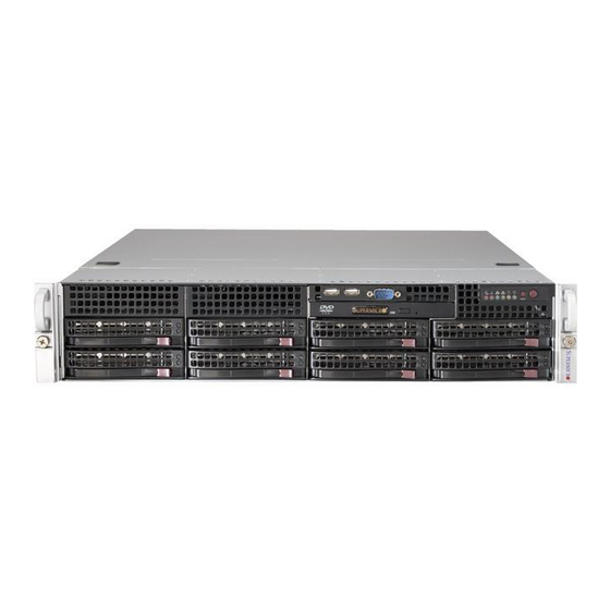
UPER ERVER 6027R-73DARF User's Manual Figure 6-1. Front and Rear Chassis Views 3.5" Drive Bays (2) DVD-ROM Drive (optional) USB Ports (2) COM Port (optional) Control Panel SAS/SATA Drives (8) System Reset Main Power Power Supplies 7 Low-profi le PCI Slots Rear I/O Ports (see Section 5-4) Control Panel The control panel (located on the front of the chassis) must be connected to the... -
Page 63: System Fans
Chapter 6: Advanced Chassis Setup System Fans Three 8-cm hot-swap fans provide the cooling for the system. It is very important that the chassis top cover is properly installed and making a good seal in order for the cooling air to circulate properly through the chassis and cool the components. See Figure 6-2. -
Page 64: Drive Bay Installation/Removal
UPER ERVER 6027R-73DARF User's Manual Figure 6-2. Removing System Cooling Fans Drive Bay Installation/Removal Accessing the Drive Bays SAS/SATA Drives: You do not need to access the inside of the chassis or remove power to replace or swap SAS/SATA drives. Proceed to the next step for instructions. You must use standard 1"... -
Page 65: Sas/Sata Drive Installation
Chapter 6: Advanced Chassis Setup SAS/SATA Drive Installation These drives are mounted in carriers to simplify their installation and removal from the chassis. The carriers also help promote proper airfl ow for the drives. For this reason, even empty carriers without hard drives installed must remain in the chassis. Removing a Drive Carrier 1. -
Page 66: Hard Drive Backplane
UPER ERVER 6027R-73DARF User's Manual Figure 6-4. Mounting a Drive in a Carrier Caution: Regardless of how many hard drives are installed, all drive car- riers must remain in the drive bays to maintain proper airfl ow. Use caution when working around the backplane. Do not touch the backplane with any metal objects and make sure no ribbon cables touch the backplane or obstruct the holes, which aid in proper airfl... -
Page 67: Power Supply
Chapter 6: Advanced Chassis Setup Power Supply The SuperServer 6027R-73DARF has a 740 watt redundant power supply consisting of two power modules. Each power supply module has an auto-switching capability, which enables it to automatically sense and operate at a 100V - 240V input voltage. - Page 68 UPER ERVER 6027R-73DARF User's Manual Notes...
-
Page 69: Chapter 7 Bios
Chapter 7: BIOS Chapter 7 BIOS Introduction This chapter describes the AMI BIOS Setup utility for the X9DRD-7JLN4F/X9DRD- 7LN4F It also provides the instructions on how to navigate the AMI BIOS Setup utility screens. The AMI ROM BIOS is stored in a Flash EEPROM and can be easily updated. -
Page 70: How To Change The Confi Guration Data
UPER ERVER 6027R-73DARF User's Manual How To Change the Confi guration Data The confi guration data that determines the system parameters may be changed by entering the AMI BIOS Setup utility. This Setup utility can be accessed by pressing <Delete> at the appropriate time during system boot. Note: For AMI UEFI BIOS Recovery, please refer to the UEFI BIOS Re- covery User Guide posted @http://www.supermicro.com/support/manuals/. - Page 71 Chapter 7: BIOS The AMI BIOS Main menu displays the following information: System Date/System Time Use this option to change the system time and date. Highlight System Time or System Date using the arrow keys. Enter new values through the keyboard and press <Enter>.
-
Page 72: Advanced Setup Confi Gurations
UPER ERVER 6027R-73DARF User's Manual Advanced Setup Confi gurations Select the Advanced tab to access the following submenu items. Boot Feature Quiet Boot This feature allows the user to select bootup screen display between POST mes- sages and the OEM logo. Select Disabled to display the POST messages. Select Enabled to display the OEM logo instead of the normal POST messages. - Page 73 Chapter 7: BIOS at bootup and allow the drives that are attached to these host adaptors to function as bootable disks. If this item is set to Disabled, the ROM BIOS of the host adap- tors will not capture Interrupt 19, and the drives attached to these adaptors will not function as bootable devices.
- Page 74 UPER ERVER 6027R-73DARF User's Manual • Processor Cores • Intel HT (Hyper-Threading) Technology • Intel VT-x Technology • Intel SMX Technology • L1 Data Cache / L1 Code Cache • L2 Cache • L3 Cache CPU Speed This item displays the speed of the CPU installed in Socket 1/Socket 2. 64-bit This item indicates if the CPU installed in Socket 1 or Socket 2 supports 64-bit technology.
- Page 75 Chapter 7: BIOS Execute-Disable Bit (Available if supported by the OS & the CPU) Select Enabled to enable the Execute Disable Bit which will allow the processor to designate areas in the system memory where an application code can execute and where it cannot, thus preventing a worm or a virus from fl...
- Page 76 UPER ERVER 6027R-73DARF User's Manual CPU Power Management Confi guration This submenu allows the user to confi gure the following CPU Power Manage- ment settings. Power Technology Select Energy Effi ciency to support power-saving mode. Select Custom to cus- tomize system power settings.
- Page 77 Chapter 7: BIOS Package C-State limit (Available when Power Technology is set to Custom) This feature allows the user to set the limit on the C-State package register. The options are C0, C2, C6, and No Limit. Energy/Performance Bias Use this feature to select an appropriate fan setting to achieve maximum system performance (with maximum cooling) or maximum energy effi...
- Page 78 UPER ERVER 6027R-73DARF User's Manual Chipset Confi guration North Bridge This feature allows the user to confi gure the settings for the Intel North Bridge. Integrated IO Confi guration Intel ® VT-d Select Enabled to enable Intel Virtualization Technology support for Direct I/O VT-d by reporting the I/O device assignments to the VMM (Virtual Machine Monitor) through the DMAR ACPI Tables.
- Page 79 Chapter 7: BIOS IIO 2 PCIe Port Bifurcation Control This submenu confi gures the following IO PCIe Port Bifurcation Control settings for IIO 2 PCIe ports to determine how the available PCI-Express lanes to be distributed between the PCI-Exp. Root ports. QPI Confi...
- Page 80 UPER ERVER 6027R-73DARF User's Manual DIMM Information CPU Socket 1 DIMM Information, CPU Socket 2 DIMM Information The status of the memory modules detected by the BIOS will be displayed as detected by the BIOS. Memory Mode When Independent is selected, all DIMMs are available to the operating system. When Mirroring is selected, the motherboard maintains two identical copies of all data in memory for data backup.
- Page 81 Chapter 7: BIOS correctable error, the error is corrected and sent to the requestor (the original source). Memory is updated as well. Select Enabled to use Demand Scrubbing for ECC memory correction. The options are Enabled and Disabled. Data Scrambling Select Enabled to enable data scrambling to ensure data security and integrity.
- Page 82 UPER ERVER 6027R-73DARF User's Manual Port 60/64 Emulation Select Enabled to enable I/O port 60h/64h emulation support for the legacy USB keyboard so that it can be fully supported by the operating systems that does not recognize a USB device. The options are Disabled and Enabled. EHCI Hand-Off This item is for operating systems that do not support Enhanced Host Controller Interface (EHCI) hand-off.
- Page 83 Chapter 7: BIOS Port 0~5 Hot Plug Select Enabled to enable hot-plug support for a particular port, which will allow the user to change a hardware component or device without shutting down the system. The options are Enabled and Disabled. Staggered Spin Up Select Enabled to enable Staggered Spin-up support to prevent excessive power consumption caused by multiple HDDs spinning-up simultaneously.
- Page 84 UPER ERVER 6027R-73DARF User's Manual SERR# Generation Select Enabled to allow a PCI device to generate an SERR number for a PCI Bus Signal Error Event. The options are Enabled and Disabled. Maximum Payload Select Auto to allow the system BIOS to automatically set the maximum payload value for a PCI-E device to enhance system performance.
- Page 85 Chapter 7: BIOS VGA Priority This feature allows the user to select the graphics adapter to be used as the primary boot device. The options are Onboard, and Offboard. Network Stack Select Enabled enable PXE (Preboot Execution Environment) or UEFI (Unifi ed Extensible Firmware Interface) for network stack support.
- Page 86 UPER ERVER 6027R-73DARF User's Manual Change Settings This option specifi es the base I/O port address and the Interrupt Request address of Serial Port 2. Select Disabled to prevent the serial port from accessing any system resources. When this option is set to Disabled, the serial port becomes unavailable. The options are Auto, IO=3F8h;...
- Page 87 Chapter 7: BIOS client computer. A lower transmission speed may be required for long and busy lines. The options are 9600, 19200, 38400, 57600 and 115200 (bits per second). Data Bits Use this feature to set the data transmission size for Console Redirection. The options are 7 Bits and 8 Bits.
- Page 88 UPER ERVER 6027R-73DARF User's Manual Putty KeyPad This feature selects Function Keys and KeyPad settings for Putty, which is a terminal emulator designed for the Windows OS. The options are VT100, LINUX, XTERMR6, SC0, ESCN, and VT400. Serial Port for Out-of-Band Management/Windows Emergency Management Services (EMS) The submenu allows the user to confi...
- Page 89 Chapter 7: BIOS Data Bits, Parity, Stop Bits The status of these features is displayed. ACPI Settings Use this feature to confi gure Advanced Confi guration and Power Interface (ACPI) power management settings for your system. ACPI Sleep State Use this feature to select the ACPI State when the system is in sleep mode. Select S1 (CPU_Stop_Clock) to erase all CPU caches and stop executing instructions.
- Page 90 UPER ERVER 6027R-73DARF User's Manual Pending Operation Use this item to schedule an operation for the security device. The options are None, Enable Take Ownership, Disable Take Ownership, and TPM Clear. Note: During restart, the computer will reboot in order to execute the pend- ing operation and change the state of the security device.
- Page 91 Chapter 7: BIOS TPM Support: Trusted Platform support TPM State: Trusted Platform state ME Subsystem This feature displays the following ME Subsystem Confi guration settings. • ME BIOS Interface Version • ME Version iSCSI Confi guration: This item displays iSCSI confi guration information: iSCSI Initiator Name This item displays the name of the iSCSI Initiator, which is a unique name used in the world.
- Page 92 UPER ERVER 6027R-73DARF User's Manual Blink LEDs This feature allows the user to specify the duration for LEDs to blink. The range is from 0 ~ 15 seconds. The default setting is 0. PORT CONFIGURATION INFORMATION This section displays the following port information: •...
-
Page 93: Event Logs
Chapter 7: BIOS Event Logs Select the Event Logs tab to access the following submenu items. Change SMBIOS Event Log Settings This feature allows the user to confi gure SMBIOS Event settings. Enabling/Disabling Options SMBIOS Event Log Select Enabled to enable SMBIOS (System Management BIOS) Event Logging during system boot. - Page 94 UPER ERVER 6027R-73DARF User's Manual Erasing Settings Erase Event Log Select Enabled to erase the SMBIOS (System Management BIOS) Event Log, which is completed before a event logging is initialized upon system reboot. The options are No, Yes, Next reset, and Yes, Every reset. When Log is Full Select Erase Immediately to immediately erase SMBIOS error event logs that ex- ceed the limit when the SMBIOS event log is full.
-
Page 95: Ipmi
Chapter 7: BIOS IPMI Select the IPMI (Intelligent Platform Management Interface) tab to access the fol- lowing submenu items. IPMI Firmware Revision This item indicates the IPMI fi rmware revision used in your system. IPMI Status This item indicates the status of the IPMI fi rmware installed in your system. ... - Page 96 UPER ERVER 6027R-73DARF User's Manual When SEL is Full This feature allows the user to decide what the BIOS should do when the system event log is full. Select Erase Immediately to erase all events in the log when the system event log is full.
-
Page 97: Boot
Chapter 7: BIOS Gateway IP Address This item displays the Gateway IP address for this computer. This should be in decimal and in dotted quad form (i.e., 192.168.10.253). Boot This submenu allows the user to confi gure the following boot settings for the system. -
Page 98: Security
UPER ERVER 6027R-73DARF User's Manual Security This menu allows the user to confi gure the following security settings for the system. Password Check Use this feature to determine when a password entry is required. Select Setup to require the password only when entering setup. Select Always to require the pass- word when entering setup and on each boot. -
Page 99: Save & Exit
Chapter 7: BIOS Save & Exit This submenu allows the user to confi gure the Save and Exit settings for the system. Discard Changes and Exit Select this option to quit the BIOS Setup without making any permanent changes to the system confi guration, and reboot the computer. Select Discard Changes and Exit, and press <Enter>. - Page 100 UPER ERVER 6027R-73DARF User's Manual Discard Changes Select this feature and press <Enter> to discard all the changes and return to the BIOS setup. When the dialog box appears, asking you if you want to load previ- ous values, select Yes to load the values previous saved, or select No to keep the changes you've made so far.
-
Page 101: Appendix A Bios Error Beep Codes
Appendix A: BIOS POST Error Codes Appendix A BIOS Error Beep Codes During the POST (Power-On Self-Test) routines, which are performed at each system boot, errors may occur. Non-fatal errors are those which, in most cases, allow the system to continue to boot. - Page 102 UPER ERVER 6027R-73DARF User's Manual Notes...
-
Page 103: Appendix B System Specifi Cations
Appendix B: System Specifi cations Appendix B System Specifi cations Processors Single or dual Intel® Xeon E5-2600 Series processors Note: Please refer to our web site for a complete listing of supported processors. Chipset Intel C602J chipset BIOS 128 Mb AMI® SPI Flash ROM Memory Capacity Sixteen DIMM sockets supporting up to 512 GB of RDIMM, ECC LRDIMM or ECC/non-ECC UDIMM DDR3-1600/1333/1066/800 type memory... - Page 104 UPER ERVER 6027R-73DARF User's Manual Weight 57 lbs. (25.9 kg.) System Cooling Three 8-cm system cooling fans System Input Requirements AC Input Voltage: 100 - 240V AC auto-range Rated Input Current: 9 - 3.5A max Rated Input Frequency: 50 to 60 Hz Power Supply Rated Output Power: 740W (Part# PWS-741P-1R) Rated Output Voltages: +12V (61.7A), +5Vsb (4A)
- Page 105 Appendix B: System Specifi cations Notes...
- Page 106 UPER ERVER 6027R-73DARF User's Manual (continued from front) The products sold by Supermicro are not intended for and will not be used in life support systems, medical equipment, nuclear facilities or systems, aircraft, aircraft devices, aircraft/emergency com- munication devices or other critical systems whose failure to perform be reasonably expected to result in signifi...
Need help?
Do you have a question about the SUPERSERVER 6027R-73DARF and is the answer not in the manual?
Questions and answers