
Related Manuals for Supero Supero SuperServer 6026TT-HDTRF


Summary of Contents for Supero Supero SuperServer 6026TT-HDTRF
- Page 1 ® UPER SuperServer 6026TT-HDTRF SuperServer 6026TT-HDIBXRF SuperServer 6026TT-HDIBQRF SuperServer 6026TT-D6RF SuperServer 6026TT-D6IBXRF SuperServer 6026TT-D6IBQRF USER’S MANUAL Revision 1.0c...
- Page 2 This product, including software and docu- mentation, is the property of Supermicro and/or its licensors, and is supplied only under a license. Any use or reproduction of this product is not allowed, except as expressly permitted by the terms of said license.
-
Page 3: About This Manual
Preface Preface About This Manual This manual is written for professional system integrators and PC technicians. It provides information for the installation and use of the SuperServer 6026TT-HDTRF/ HDIBXRF/HDIBQRF/6026TT-D6RF/D6IBXRF/D6IBQRF. Installation and mainte- nance should be performed by experienced technicians only. The SuperServer 6026TT-HD/D6 series server is a 2U Twin (two serverboards/ nodes in a 2U chassis) rackmount server based on the SC827HD-R1400B server chassis and four Super X8DTT-HF+/X8DTT-HIBXF+/X8DTT-HIBQF+ serverboards. - Page 4 SUPERSERVER 6026TT-HD/D6 Series User's Manual and memory components, this chapter will refer you to the appropriate sections of the manual for their installation. Chapter 3: System Interface Refer to this chapter for details on the system interface, which includes the functions and information provided by the control panel on the chassis as well as other LEDs located throughout the system.
- Page 5 Preface Notes...
-
Page 6: Table Of Contents
Cooling System ....................1-5 2U Twin: System Notes ................... 1-6 Nodes ......................1-6 System Power ....................1-6 Backplane/Drives .................... 1-6 Contacting Supermicro ..................1-7 Chapter 2 Server Installation Overview ......................2-1 Unpacking the System ..................2-1 Preparing for Setup ..................2-1 Choosing a Setup Location ................ - Page 7 Table of Contents Circuit Overloading ..................2-3 Reliable Ground ..................2-3 Removing the Protective Film ................. 2-4 Rack Mounting Instructions ................2-5 Separating the Sections of the Rack Rails ............. 2-5 Installing the Inner Rail Extensions ..............2-6 Outer Rack Rails ..................... 2-7 Checking the Serverboard Setup ..............
- Page 8 SUPERSERVER 6026TT-HD/D6 Series User's Manual Adding PCI Cards ................... 5-8 Serverboard Details ..................5-9 Serverboard Quick Reference............... 5-10 Connector Defi nitions ..................5-11 Jumper Settings .................... 5-15 Onboard Indicators ..................5-17 5-10 SATA and SAS Ports ..................5-18 5-11 Installing Additional Drivers ................5-19 SuperDoctor III ....................
-
Page 9: Chapter 1 Introduction
SATA/SAS cables. For your system to work properly, please follow the links below to download all necessary drivers/utilities and the user’s manual for your server. • Supermicro product manuals: http://www.supermicro.com/support/manuals/ • Product drivers and utilities: ftp://ftp.supermicro.com... -
Page 10: Serverboard Features
Processors Each X8DTT-HF+/X8DTT-HIBXF+/X8DTT-HIBQF+ supports two Intel® 5600/5500 Series processors in LGA1366 sockets. Please refer to our web site for a complete listing of supported processors (www.supermicro.com). Memory Each X8DTT-HF+/X8DTT-HIBXF+/X8DTT-HIBQF+ has twelve DIMM sockets that can support up to 192 GB of registered ECC DDR3-1333/1066/800 SDRAM, or 48 GB of unbuffered non-ECC 1333/1066/800 SDRAM. -
Page 11: Pci Expansion Slots
Chapter 1: Introduction PCI Expansion Slots Each X8DTT-HF+/X8DTT-HIBXF+/X8DTT-HIBQF+ has included riser cards that allow it to support two full-sized PCI Express 2.0 x8 expansion cards (in x16 slots), or four total for the server. Ethernet Ports An Intel® network controller is integrated into each of the serverboards to support two Gigabit LAN ports (100/1000Base-T/1000BaseTX, RJ45 output). - Page 12 SUPERSERVER 6026TT-HD/D6 Series User's Manual PROCESSOR#0 PROCESSOR#1 Intel 82574 MT25408 Connect-X IB QSFP PCI-E Gen2/DDR or QDR (For 36D Only) Intel 5520/5500 82574 36-D/24-D PCI-E x16 Slot AT25 DF321 ICH10R 4 SATA Hotswap Connector LPCIO W83527 BMC/VGA RMII VGA CONN RTL8201N PHY Dedicated LAN Figure 1-1.
-
Page 13: Server Chassis Features
Chapter 1: Introduction Server Chassis Features The following is a general outline of the main features of the SC827HD-R1400B 2U chassis. Details on the chassis can be found in Chapter 6. System Power When confi gured as a SuperServer 6026TT-HD/D6 series server, the SC827HD- R1400B includes a redundant (dual) 1400W power supply, which provides power to all four serverboards (nodes). -
Page 14: Twin: System Notes
SUPERSERVER 6026TT-HD/D6 Series User's Manual 2U Twin: System Notes As a 2U Twin confi guration, the 6026TT-HD/D6 series is a unique server system. With two system boards incorporated into a single chassis acting as two separate nodes, there are several points you should keep in mind. Nodes Each of the two serverboards act as a separate node in the system. -
Page 15: Contacting Supermicro
Super Micro Computer, Inc. 980 Rock Ave. San Jose, CA 95131 U.S.A. Tel: +1 (408) 503-8000 Fax: +1 (408) 503-8008 Email: marketing@supermicro.com (General Information) support@supermicro.com (Technical Support) Web Site: www.supermicro.com Europe Address: Super Micro Computer B.V. Het Sterrenbeeld 28, 5215 ML... - Page 16 SUPERSERVER 6026TT-HD/D6 Series User's Manual Notes...
-
Page 17: Chapter 2 Server Installation
Chapter 2: Server Installation Chapter 2 Server Installation Overview This chapter provides a quick setup checklist to get the system up and running. Fol- lowing these steps in the order given should enable you to have the system opera- tional within a minimum amount of time. This quick setup assumes that your system has come to you with the processors and memory preinstalled. -
Page 18: Warnings And Precautions
SUPERSERVER 6026TT-HD/D6 Series User's Manual • This product is not suitable for use with visual display work place devices ac- cording to §2 of the the German Ordinance for Work with Visual Display Units. Warnings and Precautions Rack Precautions • Ensure that the leveling jacks on the bottom of the rack are fully extended to the fl... -
Page 19: Rack Mounting Considerations
Chapter 2: Server Installation Rack Mounting Considerations Ambient Operating Temperature If installed in a closed or multi-unit rack assembly, the ambient operating tempera- ture of the rack environment may be greater than the ambient temperature of the room. Therefore, consideration should be given to installing the equipment in an environment compatible with the manufacturer’s maximum rated ambient tempera- ture (Tmra). -
Page 20: Removing The Protective Film
SUPERSERVER 6026TT-HD/D6 Series User's Manual Removing the Protective Film Before operating the server for the fi rst time, it is important to remove the protec- tive fi lm covering the top of the chassis, in order to allow for proper ventilation and cooling. -
Page 21: Rack Mounting Instructions
Chapter 2: Server Installation Rack Mounting Instructions This section provides information on installing the SC827 chassis into a rack unit with the quick-release rails provided. There are a variety of rack units on the market, which may mean the assembly procedure will differ slightly. You should also refer to the installation instructions that came with the rack unit you are using. -
Page 22: Installing The Inner Rail Extensions
SUPERSERVER 6026TT-HD/D6 Series User's Manual Installing the Inner Rail Extensions The SC827 chassis includes a set of inner rails in two sections: inner rails and inner rail extensions. The inner rails are pre-attached to the chassis, and do not interfere with normal use of the chassis if you decide not to use a server rack. -
Page 23: Outer Rack Rails
Chapter 2: Server Installation Figure 2-4. Assembling the Outer Rails Outer Rack Rails Outer rails attach to the rack and hold the chassis in place. The outer rails for the SC827 chassis extend between 30 inches and 33 inches. Installing the Outer Rails to the Rack 1. - Page 24 SUPERSERVER 6026TT-HD/D6 Series User's Manual Figure 2-5. Installing Into the Rack Installing the Chassis into a Rack 1. Extend the outer rails as illustrated above. 2. Align the inner rails of the chassis with the outer rails on the rack. 3.
-
Page 25: Checking The Serverboard Setup
Chapter 2: Server Installation Checking the Serverboard Setup After you install the system in the rack, you will need to access the inside of the nodes to make sure the serverboard is properly installed. Accessing the Inside of a Node (Figure 2-6) 1. -
Page 26: Preparing To Power On
SUPERSERVER 6026TT-HD/D6 Series User's Manual Preparing to Power On Next, you should check to make sure the SATA drives and the backplane have been properly installed and all connections have been made. Checking the Hard Drives 1. The hard drives are accessable from the front of the server and can be installed and removed from the front of the chassis without removing the top chassis cover. - Page 27 Chapter 2: Server Installation Figure 2-6. Removing a Node from the System 2-11...
- Page 28 SUPERSERVER 6026TT-HD/D6 Series User's Manual Notes 2-12...
-
Page 29: Chapter 3 System Interface
Chapter 3: System Interface Chapter 3 System Interface Overview There are LEDs on the control panels and on the hard drive carriers to keep you constantly informed of the overall status of the system as well as the activity and health of specifi... -
Page 30: Control Panel Leds
SUPERSERVER 6026TT-HD/D6 Series User's Manual Control Panel LEDs In addition to the LEDs built into the power and UID buttons, each of the four control panels located on the front of the SC827HD-R1400B chassis has two LEDs that provide you with critical information related their own node. This section explains what each LED indicates when illuminated and any corrective action you may need to take. -
Page 31: Chapter 4 Standardized Warning Statements For Ac Systems
Only certifi ed technicians should attempt to install or confi gure components. Read this appendix in its entirety before installing or confi guring components in the Supermicro chassis. These warnings may also be found on our web site at http://www.supermicro.com/ about/policies/safety_information.cfm. Warning Defi nition Warning! This warning symbol means danger. - Page 32 SUPERSERVER 6026TT-HD/D6 Series User's Manual Warnung WICHTIGE SICHERHEITSHINWEISE Dieses Warnsymbol bedeutet Gefahr. Sie befi nden sich in einer Situation, die zu Verletzungen führen kann. Machen Sie sich vor der Arbeit mit Geräten mit den Gefahren elektrischer Schaltungen und den üblichen Verfahren zur Vorbeugung vor Unfällen vertraut.
- Page 33 Warning Statements for AC Systems ﺟﺴﺪﻳﺔ ﺍﺻﺎﺑﺔ ﺗﺘﺴﺒﺐ ﻓﻲ ﺣﺎﻟﺔ ﻳﻤﻜﻦ ﺃﻥ ﺍﻧﻚ ﻓﻲ ﺧﻄﺮ ﻳﻌﻨﻲ ﻫﺬﺍ ﺍﻟﺮﻣﺰ !ﺗﺤﺬﻳﺮ ﺍﻟﺪﻭﺍﺋﺮ ﺑﺎﻟﻤﺨﺎﻁﺮ ﺍﻟﻨﺎﺟﻤﺔ ﻋﻦ ﻦ ﻋﻠﻰ ﻋﻠﻢ ، ﻛ ﻣﻌﺪﺍﺕ ﺗﻌﻤﻞ ﻋﻠﻰ ﺃﻱ ﻗﺒﻞ ﺃﻥ ﺍﻟﻜﻬﺮﺑﺎﺋﻴﺔ ﺣﻮﺍﺩﺙ ﺃﻱ ﻭﻗﻮﻉ ﻤﻨﻊ ﻟ ﺍﻟﻮﻗﺎﺋﻴﺔ...
-
Page 34: Installation Instructions
SUPERSERVER 6026TT-HD/D6 Series User's Manual Installation Instructions Warning! Read the installation instructions before connecting the system to the power source. 警告 将此系统连接电源前,请先阅读安装说明。 警告 將系統與電源連接前,請先閱讀安裝說明。 Warnung Vor dem Anschließen des Systems an die Stromquelle die Installationsanweisungen lesen. ¡Advertencia! Lea las instrucciones de instalación antes de conectar el sistema a la red de alimentación. -
Page 35: Circuit Breaker
Chapter 4: Warning Statements for AC Systems Circuit Breaker Warning! This product relies on the building's installation for short-circuit (overcurrent) protection. Ensure that the protective device is rated not greater than: 250 V, 20 A. 警告 此产品的短路(过载电流)保护由建筑物的供电系统提供,确保短路保护设备的额定电 流不大于250V,20A。 警告 此產品的短路(過載電流)保護由建築物的供電系統提供,確保短路保護設備的額定電 流不大於250V,20A。... -
Page 36: Power Disconnection Warning
SUPERSERVER 6026TT-HD/D6 Series User's Manual Waarschuwing Dit product is afhankelijk van de kortsluitbeveiliging (overspanning) van uw electrische installatie. Controleer of het beveiligde aparaat niet groter gedimensioneerd is dan 220V, 20A. Power Disconnection Warning Warning! The system must be disconnected from all sources of power and the power cord removed from the power supply module(s) before accessing the chassis interior to install or remove system components. - Page 37 Chapter 4: Warning Statements for AC Systems ¡Advertencia! El sistema debe ser disconnected de todas las fuentes de energía y del cable eléctrico quitado de los módulos de fuente de alimentación antes de tener acceso el interior del chasis para instalar o para quitar componentes de sistema. Attention Le système doit être débranché...
-
Page 38: Equipment Installation
SUPERSERVER 6026TT-HD/D6 Series User's Manual Equipment Installation Warning! Only trained and qualifi ed personnel should be allowed to install, replace, or service this equipment. 警告 只有经过培训且具有资格的人员才能进行此设备的安装、更换和维修。 警告 只有經過受訓且具資格人員才可安裝、更換與維修此設備。 Warnung Das Installieren, Ersetzen oder Bedienen dieser Ausrüstung sollte nur geschultem, qualifi ziertem Personal gestattet werden. ¡Advertencia! Solamente el personal califi... -
Page 39: Restricted Area
Chapter 4: Warning Statements for AC Systems Waarschuwing Deze apparatuur mag alleen worden geïnstalleerd, vervangen of hersteld door geschoold en gekwalifi ceerd personeel. Restricted Area Warning! This unit is intended for installation in restricted access areas. A restricted access area can be accessed only through the use of a special tool, lock and key, or other means of security. -
Page 40: Battery Handling
SUPERSERVER 6026TT-HD/D6 Series User's Manual אזור עם גישה מוגבלת !אזהרה יש להתקין את היחידה באזורים שיש בהם הגבלת גישה. הגישה ניתנת בעזרת .('כלי אבטחה בלבד )מפתח, מנעול וכד ﻣﺤﻈﻮﺭﺓ ﻣﻨﺎﻁﻖ ﻟﺘﺮﻛﻴﺒﻬﺎ ﻓﻲ ﻫﺬﻩ ﺍﻟﻮﺣﺪﺓ ﺗﺨﺼﻴﺺ ﺗﻢ ،ﺃﺩﺍﺓ ﺧﺎﺻﺔ ﻣﻦ ﺧﻼﻝ ﺍﺳﺘﺨﺪﺍﻡ ﻓﻘﻂ... - Page 41 Chapter 4: Warning Statements for AC Systems Warnung Bei Einsetzen einer falschen Batterie besteht Explosionsgefahr. Ersetzen Sie die Batterie nur durch den gleichen oder vom Hersteller empfohlenen Batterietyp. Entsorgen Sie die benutzten Batterien nach den Anweisungen des Herstellers. Attention Danger d'explosion si la pile n'est pas remplacée correctement. Ne la remplacer que par une pile de type semblable ou équivalent, recommandée par le fabricant.
-
Page 42: Redundant Power Supplies
SUPERSERVER 6026TT-HD/D6 Series User's Manual Redundant Power Supplies Warning! This unit might have more than one power supply connection. All connections must be removed to de-energize the unit. 警告 此部件连接的电源可能不止一个,必须将所有电源断开才能停止给该部件供电。 警告 此裝置連接的電源可能不只一個,必須切斷所有電源才能停止對該裝置的供電。 Warnung Dieses Gerät kann mehr als eine Stromzufuhr haben. Um sicherzustellen, dass der Einheit kein trom zugeführt wird, müssen alle Verbindungen entfernt werden. -
Page 43: Backplane Voltage
Chapter 4: Warning Statements for AC Systems ﺍﻣﺪﺍﺩ ﺍﻟﻄﺎﻗﺔ ﺑﻮﺣﺪﺍﺕ ﻋﺪﺓ ﺍﺗﺼﺎﻻﺕ ﺠﻬﺎﺯ ﺍﻟ ﻳﻜﻮﻥ ﻟﻬﺬﺍ ﻗﺪ ﺍﻟﻜﻬﺮﺑﺎء ﻋﻦ ﻮﺣﺪﺓ ﺍﻟ ﻟﻌﺰﻝ ﻛﺎﻓﺔ ﺍﻻﺗﺼﺎﻻﺕ ﻳﺠﺐ ﺇﺯﺍﻟﺔ Waarschuwing Deze eenheid kan meer dan één stroomtoevoeraansluiting bevatten. Alle aansluitingen dienen verwijderd te worden om het apparaat stroomloos te maken. Backplane Voltage Warning! Hazardous voltage or energy is present on the backplane when the system is... -
Page 44: Comply With Local And National Electrical Codes
SUPERSERVER 6026TT-HD/D6 Series User's Manual מתח בפנל האחורי !הרה אז קיימת סכנת מתח בפנל האחורי בזמן תפעול המערכת. יש להיזהר במהלך .העבודה ﺍﻟﻠﻮﺣﺔ ﺃﻭﺍﻟﻄﺎﻗﺔ ﺍﻟﻤﻮﺟﻮﺩﺓ ﻋﻠﻰ ﺍﻟﺘﻴﺎﺭ ﺍﻟﻜﻬﺮﺑﺎﺋﻲ ﻣﻦ ﺧﻄﺮ ﻫﻨﺎﻙ ﻫﺬﺍ ﺍﻟﺠﻬﺎﺯ ﺧﺪﻣﺔ ﻛﻦ ﺣﺬﺭﺍ ﻋﻨﺪ ﻳﻌﻤﻞ ﺍﻟﻨﻈﺎﻡ ﻋﻨﺪﻣﺎ ﻳﻜﻮﻥ Waarschuwing Een gevaarlijke spanning of energie is aanwezig op de backplane wanneer het systeem in gebruik is. -
Page 45: Product Disposal
Chapter 4: Warning Statements for AC Systems Attention L'équipement doit être installé conformément aux normes électriques nationales et locales. תיאום חוקי החשמל הארצי !אזהרה הציוד חייבת להיות תואמת לחוקי החשמל המקומיים והארציים התקנת ﺍﻟﻤﺘﻌﻠﻘﺔ ﺍﻟﻤﺤﻠﻴﺔ ﻭﺍﻟﻮﻁﻨﻴﺔ ﻘﻮﺍﻧﻴﻦ ﻳﺠﺐ ﺃﻥ ﻳﻤﺘﺜﻞ ﻟﻠ ﺍﻟﻜﻬﺮﺑﺎﺋﻴﺔ... -
Page 46: Hot Swap Fan Warning
SUPERSERVER 6026TT-HD/D6 Series User's Manual ¡Advertencia! Al deshacerse por completo de este producto debe seguir todas las leyes y reglamentos nacionales. Attention La mise au rebut ou le recyclage de ce produit sont généralement soumis à des lois et/ou directives de respect de l'environnement. Renseignez-vous auprès de l'organisme compétent. - Page 47 Chapter 4: Warning Statements for AC Systems 警告 當您從機架移除風扇裝置,風扇可能仍在轉動。小心不要將手指、螺絲起子和其他 物品太靠近風扇。 Warnung Die Lüfter drehen sich u. U. noch, wenn die Lüfterbaugruppe aus dem Chassis genommen wird. Halten Sie Finger, Schraubendreher und andere Gegenstände von den Öffnungen des Lüftergehäuses entfernt. ¡Advertencia! Los ventiladores podran dar vuelta cuando usted quite ell montaje del ventilador del chasis.
-
Page 48: Power Cable And Ac Adapter
fi re. Electrical Appliance and Material Safety Law prohibits the use of UL or CSA -certifi ed cables (that have UL/CSA shown on the code) for any other electrical devices than products designated by Supermicro only. 警告... - Page 49 Appareils électroménagers et de loi sur la sécurité Matériel interdit l'utilisation de UL ou CSA câbles certifi és qui ont UL ou CSA indiqué sur le code pour tous les autres appareils électriques que les produits désignés par Supermicro seulement.
- Page 50 SUPERSERVER 6026TT-HD/D6 Series User's Manual Notes 4-20...
-
Page 51: Chapter 5 Advanced Serverboard Setup
Chapter 5: Advanced Serverboard Setup Chapter 5 Advanced Serverboard Setup This chapter covers the steps required to install the X8DTT-HF+/X8DTT-HIBXF+/ X8DTT-HIBQF+ serverboard into the SC827HD-R1400B chassis, connect the data and power cables and install add-on cards. All serverboard jumpers and connections are also described. -
Page 52: I/O Ports
SUPERSERVER 6026TT-HD/D6 Series User's Manual Unpacking The serverboard is shipped in antistatic packaging to avoid electrostatic discharge. When unpacking the board, make sure the person handling it is static protected. I/O Ports The I/O ports are color coded in conformance with the PC 99 specifi cation. See Figure 5-1 below for the colors and locations of the various I/O ports. -
Page 53: Processor And Heatsink Installation
CPU socket cap is in place and none of the socket pins are bent; otherwise, contact your retailer immediately. • Refer to the Supermicro web site for updates on CPU support. Installing LGA1366 Processors 1. Starting with CPU1, press the... - Page 54 SUPERSERVER 6026TT-HD/D6 Series User's Manual 1. After removing the plastic cap, use your thumb and the index fi nger to hold the CPU at the north and south center edges. 2. Align the CPU key (the semi-circle cutout) with the socket key (the notch below the gold color dot on the side of the socket).
-
Page 55: Installing A Cpu Heatsink
Chapter 5: Advanced Serverboard Setup Installing a CPU Heatsink 1. Remove power from the system and unplug the AC power cord from the power supply. 2. Do not apply any thermal grease to the heatsink or the CPU die; the required amount has already been applied. -
Page 56: Installing Memory
GB of unbuffered ECC/non-ECC DDR3-1333/1066/800 MHz in 12 DIMM slots (max. of 16 GB of registered ECC and 4 GB of unbuffered memory per DIMM slot.). Note: Check the Supermicro web site for recommended DIMMs. Installing Memory Modules 1. Insert each memory module vertically into a slot following the charts below. - Page 57 Chapter 5: Advanced Serverboard Setup DIMM Population Table Ranks per DIMM DIMM DIMMs (any combination; DIMM Type (Reg.= Slots per Populated Speeds (in MHz) SR=Single Rank, Registered) Channel per Channel DR=Dual Rank, QR=Quad Rank) Reg. DDR3 ECC 800,1066,1333 SR or DR Reg.
-
Page 58: Adding Pci Cards
SUPERSERVER 6026TT-HD/D6 Series User's Manual Due to the memory allocation to system devices, the amount of memory that remains available for operational use will be reduced when 4 GB of RAM is used. The reduction in memory availability is disproportional. Refer to the table below. Possible System Memory Allocation &... -
Page 59: Serverboard Details
Chapter 5: Advanced Serverboard Setup Serverboard Details Figure 5-3. X8DTT-H+ Series Serverboard Layout COM1 LAN2 LAN1 USB0/1 InfinBand JSPK1 IPMI_LAN Connector Winbond InfiniBand LAN CTRL1 CTRL WPCM450 LAN CTRL2 C384 JUSB2 JLPC80 JBT1 CLEAR CMOS Intel ICH10R South Bridge BIOS Intel 5520 (IOH-36D) Intel 5500 (IOH-24D) (For OEM only) -
Page 60: Serverboard Quick Reference
SUPERSERVER 6026TT-HD/D6 Series User's Manual Serverboard Quick Reference Jumper Description Default Setting JBT1 CMOS Clear (See Section 5-8) JPG1 VGA Enable/Disable Pins 1-2 (Enabled) JPL1/JPL2 LAN1/2 Enable/Disable Pins 1-2 (Enabled) JWD1 Watch Dog Enable/Disable/Reset Pins 1-2 (Reset) Connector Description COM1 COM1 Serial Port FAN 1 Cooling Fan Header... -
Page 61: Connector Defi Nitions
Chapter 5: Advanced Serverboard Setup Connector Defi nitions Front Panel Accessible Add-on Card Header (JF2) The JF2 add-on card header provides front access to the power supply, Serial ATA and Front Panel Control connections for the X8DTT-H Series motherboard. Plug an Add-On card into this header to use the functions indicated above. - Page 62 SUPERSERVER 6026TT-HD/D6 Series User's Manual Fan Header Fan Header Pin Defi nitions The X8DTT-H series motherboard has Pin# Defi nition one fan header on the motherboard. This Ground 4-pin header is backward compatible with +12V traditional 3-pin fans, however, fan speed Tachometer control is only available for 4-pin fans.
- Page 63 Chapter 5: Advanced Serverboard Setup Ethernet Ports LAN Ports Pin Defi nitions Two Ethernet ports are located next to Pin# Defi nition Pin# Defi nition USB0/1 on the IO Backplane. In addition, P2V5SB SGND an IPMI Dedicated LAN is located above TD0+ Act LED USB0/1.
- Page 64 SUPERSERVER 6026TT-HD/D6 Series User's Manual Serial Ports Serial Port Pin Defi nitions Pin Defi nitions One serial port is included on the serverboard. Pin # Defi nition Pin # Defi nition The COM port is located beside the VGA port. See the table on the right for pin defi ni- tions.
-
Page 65: Jumper Settings
Chapter 5: Advanced Serverboard Setup Jumper Settings Connector To modify the operation of the serverboard, Pins jumpers can be used to choose between optional settings. Jumpers create shorts between two pins to change the function Jumper of the connector. Pin 1 is identifi ed with a square solder pad on the printed circuit board. - Page 66 SUPERSERVER 6026TT-HD/D6 Series User's Manual LAN1/LAN2 Enable/Disable LAN1/2 Enable/Disable Jumper Settings Change the setting of jumper JPL1/JPL2 Jumper Setting Defi nition to enable or disable the LAN1 and LAN2 Pins 1-2 Enabled ports respectively. See the table on the right Pins 2-3 Disabled for jumper settings.
-
Page 67: Onboard Indicators
Chapter 5: Advanced Serverboard Setup Onboard Indicators LAN1/LAN2 LEDs LAN1/LAN2 LEDs (Connection Speed The Ethernet ports (located beside the COM Indicator) port) have two LEDs. On each Gb LAN port, LED Color Defi nition one LED indicates activity when blinking No connection or while the other LED may be green, amber or 10 Mb/s... -
Page 68: 5-10 Sata And Sas Ports
SUPERSERVER 6026TT-HD/D6 Series User's Manual BMC Activity LED (LE2) A BMC Heartbeat LED is located at LE2 BMC Heartbeat LED on the motherboard. When LE2 is on, BMC is normal BMC (Baseboard Management Controller) is active. See the table at right for more information. -
Page 69: 5-11 Installing Additional Drivers
Chapter 5: Advanced Serverboard Setup 5-11 Installing Additional Drivers The Supermicro ftp site contains drivers and utilities for your system at ftp://ftp. supermicro.com. Some of these must be installed, such as the chipset driver. After accessing the ftp site, go into the CDR_Images directory and locate the ISO fi... -
Page 70: Superdoctor Iii
SUPERSERVER 6026TT-HD/D6 Series User's Manual SuperDoctor III The SuperDoctor® III program is a web-based management tool that supports remote management capability. It includes Remote and Local Management tools. The local management is called SD III Client. The SuperDoctor III program allows you to monitor the environment and operations of your system. - Page 71 Chapter 5: Advanced Serverboard Setup Figure 5-6. SuperDoctor III Interface Display Screen (Remote Control) Note: The SuperDoctor III program and User’s Manual can be downloaded from the Supermicro web site at http://www.supermicro.com/products/accessories/soft- ware/SuperDoctorIII.cfm. For Linux, we recommend that you use the SuperDoctor II application instead.
-
Page 72: 5-12 Onboard Battery
SUPERSERVER 6026TT-HD/D6 Series User's Manual 5-12 Onboard Battery Please handle used batteries carefully. Do not damage the battery in any way; a damaged battery may release hazardous materials into the environment. Do not discard a used battery in the garbage or a public landfi ll. Please comply with the regulations set up by your local hazardous waste management agency to dispose of your used battery properly. -
Page 73: Chapter 6 Advanced Chassis Setup
Chapter 6: Advanced Chassis Setup Chapter 6 Advanced Chassis Setup This chapter covers the steps required to install components and perform main- tenance on the SC827HD-R1400B chassis. For component installation, follow the steps in the order given to eliminate the most common problems encountered. If some steps are unnecessary, skip ahead to the step that follows. -
Page 74: Control Panel
SUPERSERVER 6026TT-HD/D6 Series User's Manual Figure 6-1. Chassis Front View Node A Control Panel Node B Control Panel Hard Drives Figure 6-2. Chassis Rear View Dedicated IPMI LAN Port Dedicated IPMI LAN Port LAN Ports PCI-Express x8 Cards Power Supply LAN Ports PCI-Express x8 Cards USB Ports COM Port VGA Port... -
Page 75: Fan Confi Guration
Chapter 6: Advanced Chassis Setup Fan Confi guration In the 2U Twin, each node (serverboard) controls the two fans that reside on its side of the chassis. If the fan speed settings in BIOS are set to different values for each two node, the BIOS setting with the higher fan speed will apply to both. -
Page 76: Hard Drive Installation/Removal
SUPERSERVER 6026TT-HD/D6 Series User's Manual Hard Drive Installation/Removal Overview The hard drives are mounted in drive carriers to simplify their installation and removal from the chassis. These carriers also help promote proper airfl ow for the system. For this reason, even empty carriers without drives installed must remain in the chassis. - Page 77 2. Swing the handle fully out and use it to pull the unit straight out (see Figure 6-5). See the following pages for the logical layout of the hot-swap drives. Warning: Enterprise level hard disk drives are recommended for use in Supermicro chassis and servers. For information on recommended HDDs, visit the Supermicro...
- Page 78 SUPERSERVER 6026TT-HD/D6 Series User's Manual Figure 6-5. Removing a Hard Drive Figure 6-6. Drives and Nodes: Logical Confi guration Note: see Figure 6-1 for the locations of the control panels that are associated with each node.
-
Page 79: Node Installation/Removal
Chapter 6: Advanced Chassis Setup Figure 6-7. Drive Bay Logical Layout Node A Drives Node B Drives Node Installation/Removal As with any server system, power must be removed from the serverboard when upgrading or installing memory or processors. In the 2U Twin server, the server- boards (nodes) are capable of being hot-swapped from the chassis, allowing one to be powered down for servicing while the other continues operating. - Page 80 SUPERSERVER 6026TT-HD/D6 Series User's Manual Figure 6-8. Removing a System Node...
-
Page 81: Installing The Air Shrouds
4 off) and remain fl ashing until the failed unit has been replaced. Replacement units can be ordered directly from Supermicro (see contact information in the Preface). The power supply units have a hot-swap capability, meaning you can replace the failed unit without powering down the system. - Page 82 SUPERSERVER 6026TT-HD/D6 Series User's Manual Figure 6-9. Removing the Power Supply Release Tab 6-10...
-
Page 83: Chapter 7 Bios
When an option is selected in the left frame, it is highlighted in white. Often a text message will accompany it. (Note: the AMI BIOS has default text messages built in. Supermicro retains the option to include, omit, or change any of these text messages.) The AMI BIOS Setup Utility uses a key-based navigation system called "hot keys". -
Page 84: Main Setup
Warning! Do not upgrade the BIOS unless your system has a BIOS-related issue. Flashing the wrong BIOS can cause irreparable damage to the system. In no event shall Supermicro be liable for direct, indirect, special, incidental, or consequential damages arising from a BIOS update. If you have to update the BIOS, do not shut down or reset the system while the BIOS is updating. - Page 85 Day MM/DD/YY format. The time is entered in HH:MM:SS format. (Note: The time is in the 24-hour format. For example, 5:30 P.M. appears as 17:30:00.) Supermicro X8DTT/-F/-IBX/-IBXF/-IBQ/-IBQF BIOS Build Version This item displays the BIOS revision used in your system.
-
Page 86: Advanced Setup Confi Gurations
SUPERSERVER 6026TT-HD/D6 Series User's Manual Advanced Setup Confi gurations Use the arrow keys to select Boot Setup and hit <Enter> to access the submenu items: BOOT Features Quick Boot If Enabled, this option will skip certain tests during POST to reduce the time needed for system boot. -
Page 87: Processor And Clock Options
Chapter 7: BIOS Hit 'Del' Message Display This feature displays "Press DEL to run Setup" during POST. The options are Enabled and Disabled. Interrupt 19 Capture Interrupt 19 is the software interrupt that handles the boot disk function. When this item is set to Enabled, the ROM BIOS of the host adaptors will "capture"... - Page 88 SUPERSERVER 6026TT-HD/D6 Series User's Manual C1E Support Select Enabled to use the feature of Enhanced Halt State. C1E signifi cantly reduces the CPU's power consumption by reducing the CPU's clock cycle and voltage during a "Halt State." The options are Disabled and Enabled. Hardware Prefetcher (Available when supported by the CPU) If set to Enabled, the hardware pre fetcher will pre fetch streams of data and instruc- tions from the main memory to the L2 cache in the forward or backward manner to...
-
Page 89: Advanced Chipset Control
Chapter 7: BIOS tion and heat dissipation. Please refer to Intel’s web site for detailed information. The options are Disable (Disable GV3) and Enable (Enable GV3). Intel® TurboMode Technology Select Enabled to use the Turbo Mode to boost system performance. The options are Enabled and Disabled. - Page 90 SUPERSERVER 6026TT-HD/D6 Series User's Manual QPI L0s and L1 This enables the QPI power state to low power. L0s and L1 are automatically selected by the motherboard. The options are Disabled and Enabled. Memory Frequency This feature forces a DDR3 frequency slower than what the system has detected. The available options are Auto, Force DDR-800, Force DDR-1066, and Force DDR-1333.
- Page 91 Chapter 7: BIOS Throttling - Closed Loop/Throttling - Open Loop Throttling improves reliability and reduces power in the processor by automatic voltage control during processor idle states. Available options are Disabled and Enabled. If Enabled, the following items will appear: Hysteresis Temperature Temperature Hysteresis is the temperature lag (in degrees Celsius) after the set DIMM temperature threshold is reached before Closed Loop Throttling...
- Page 92 SUPERSERVER 6026TT-HD/D6 Series User's Manual North Bridge Confi guration This feature allows the user to confi gure the settings for the Intel IOH chip. Crystal Beach/DMA (Direct Memory Access) This feature works with the Intel I/O AT (Acceleration Technology) to accelerate the performance of TOE devices.
- Page 93 Chapter 7: BIOS USB 2.0 Controller Select Enabled to activate the onboard USB 2.0 controller. The options are Enabled and Disabled. USB 2.0 Controller Mode This setting allows you to select the USB 2.0 Controller mode. The options are Hi-Speed (480 Mbps) and Full Speed (12 Mbps). BIOS EHCI Hand-Off Select Enabled to enable BIOS Enhanced Host Controller Interface support to provide a workaround solution for an operating system that does not have EHCI...
- Page 94 SUPERSERVER 6026TT-HD/D6 Series User's Manual Hot Plug (This feature is available when the option-Enabled is selected) Select Enable to enable the hot plug function for the SATA devices. The options are Enabled and Disabled. SATA#2 Confi guration Selecting Enhanced will set SATA#2 to native SATA mode. The options are Disabled, and Enhanced.
- Page 95 Chapter 7: BIOS Select 0 to allow the AMI BIOS to use PIO mode 0. It has a data transfer rate of 3.3 MBs. Select 1 to allow the AMI BIOS to use PIO mode 1. It has a data transfer rate of 5.2 MBs.
- Page 96 SUPERSERVER 6026TT-HD/D6 Series User's Manual Select UDMA5 to allow the BIOS to use Ultra DMA mode 5. It has a data transfer rate of 133 MBs. Select UDMA6 to allow the BIOS to use Ultra DMA mode 6. It has a data transfer rate of 133 MBs.
- Page 97 Chapter 7: BIOS Load Onboard LAN1 Option ROM/Load Onboard LAN2 Option ROM Select Enabled to enable the onboard LAN1 or LAN2 Option ROM. This is to boot computer using a network interface. The options are Enabled and Disabled. Super IO Device Confi guration Serial Port1 Address/ Serial Port2 Address This option specifi...
-
Page 98: Hardware Health Monitor
SUPERSERVER 6026TT-HD/D6 Series User's Manual Terminal Type This feature allows the user to select the target terminal type for Console Redirec- tion. The options are ANSI, VT100, and VT-UTF8. VT-UTF8 Combo Key Support A terminal keyboard defi nition that provides a way to send commands from a remote console. - Page 99 ‘Temperature Tolerance’ is, and not the other way around. This results in better CPU thermal management. Supermicro has leveraged this feature by assigning a temperature status to certain thermal conditions in the processor (Low, Medium and High). This makes it easier for the user to understand the CPU’s temperature status, rather than by just simply...
- Page 100 SUPERSERVER 6026TT-HD/D6 Series User's Manual User intervention: If the system buzzer and Overheat LED has activated, take action immediately by checking the system fans, chassis ventilation and room temperature to correct any problems. Notes: 1. The system may shut down if it continues for a long period to prevent damage to the CPU.
- Page 101 Chapter 7: BIOS APIC ACPI SCI IRQ When this item is set to Enabled, APIC ACPI SCI IRQ is supported by the system. The options are Enabled and Disabled. Headless Mode This feature is used to enable system to function without a keyboard, monitor or mouse attached The options are Enabled and Disabled.
- Page 102 SUPERSERVER 6026TT-HD/D6 Series User's Manual View BMC System Event Log This feature displays the BMC System Event Log (SEL). It shows the total num- ber of entries of BMC System Events. To view an event, select an Entry Number and pressing <Enter>...
- Page 103 Chapter 7: BIOS IP Address Source Select the source of this machine's IP address. If Static is selected, you will need to know and enter manually the IP address of this machine below. If DHCP is selected, the BIOS will search for a DHCP (Dynamic Host Confi guration Protocol) server in the network it is attached to, and request the next available IP address.
- Page 104 SUPERSERVER 6026TT-HD/D6 Series User's Manual Subnet Mask This item displays the current subnet mask setting for your IPMI connection. Current Subnet Mask in BMC This item displays the current subnet mask used for your IPMI connection. Gateway Address Confi guration Enter the gateway address for this machine.
-
Page 105: Security Settings
Chapter 7: BIOS DMI Event Log View Event Log Use this option to view the System Event Log. Mark all events as read This option marks all events as read. The options are OK and Cancel. Clear event log This option clears the Event Log memory of all messages. The options are OK and Cancel. -
Page 106: Boot Confi Guration
SUPERSERVER 6026TT-HD/D6 Series User's Manual Password Check This item allows you to check a password after it has been entered. The options are Setup and Always. Boot Sector Virus Protection When Enabled, the AMI BOIS displays a warning when any program (or virus) is- sues a Disk Format command or attempts to write to the boot sector of the hard disk drive. -
Page 107: Hard Disk Drives
Chapter 7: BIOS Hard Disk Drives This feature allows the user to specify the boot sequence from all available hard disk drives. The settings are Disabled and a list of all hard disk drives that have been detected (i.e., 1st Drive, 2nd Drive, 3rd Drive, etc). •... -
Page 108: Exit Options
Warning! Do not upgrade the BIOS unless your system has a BIOS-related issue. Flashing the wrong BIOS can cause irreparable damage to the system. In no event shall Supermicro be liable for direct, indirect, special, incidental, or consequential damages arising from a BIOS update. If you need to update the BIOS, do not shut down or reset the system while the BIOS is updating. - Page 109 Note: BIOS Recovery described below is used when the main BIOS block crashes. However, when the BIOS Boot sector crashes, you will need to send the mother- board back to Supermicro for RMA repairs. Boot Sector Recovery from a USB Device This feature allows the user to recover a BIOS image using a USB device without additional utilities needed.
- Page 110 SUPERSERVER 6026TT-HD/D6 Series User's Manual Boot Sector Recovery from a Serial Port ("Serial Flash") This process, also known as "Serial Flash," allows the user to use a serial port to load a BIOS image for Boot Sector recovery. This feature is usually used for embed- ded systems that rely on a serial port for remote access and debugging.
- Page 111 Chapter 7: BIOS 4. Power on your system and click the <Connect> button in the Hyper Terminal. The terminal screen will display the following messages. 5. Following the instructions given on the screen to update the BIOS. These instructions are also shown below. a.
- Page 112 SUPERSERVER 6026TT-HD/D6 Series User's Manual 6. Once you've completed the instructions given, a screen will display to indicate that remote fl ashing is starting and the new BIOS fi le is being uploaded. 7. To use Hyper Terminal to transfer the XModem protocol by using the "Send File"...
-
Page 113: Appendix A Bios Error Beep Codes
Appendix A: BIOS Error Beep Codes Appendix A BIOS Error Beep Codes During the POST (Power-On Self-Test) routines, which are performed each time the system is powered on, errors may occur. Non-fatal errors are those which, in most cases, allow the system to continue the boot-up process. - Page 114 SUPERSERVER 6026TT-HD/D6 Series User's Manual Notes...
-
Page 115: Appendix B Installing Windows
South Bridge RAID Settings before you install the Windows OS and other software drivers. To confi gure RAID settings, please refer to RAID Confi guration User Guides posted on our web site at www.supermicro.com/support/manuals. B-1 Installing Windows for a RAID System 1. - Page 116 Windows XP/2003 installation. 4. After the Windows XP/2003 OS Installation is completed, the system will automatically reboot. 5. Insert the Supermicro Setup CD that came with your motherboard into the CD Drive during system boot, and the main screen will display.
-
Page 117: Appendix C System Specifi Cations
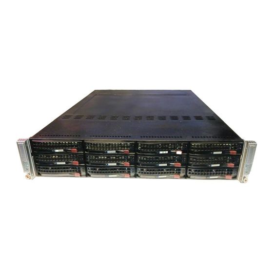
Appendix C: System Specifi cations Appendix C System Specifi cations Note: unless noted specifi cations apply to a complete system (two serverboards). Processors Four Intel® 5600/5500 Series processors in LGA1366 sockets Note: Please refer to our website for details on supported processors. Chipset Intel 5520/ICH10R BIOS... - Page 118 SUPERSERVER 6026TT-HD/D6 Series User's Manual Serverboard 6026TT-HDTRF/ 6026TT-D6RF: X8DTT-HF+ 6026TT-HDIBXRF/ 6026TT-D6IBXRF: X8DTT-HIBXF+ 6026TT-HDIBQRF/ 6026TT-D6IBQRF: X8DTT-HIBQF+ Dimensions (all): 16.64" (L) x 6.80" (W) (422.66 mm x 172.72 mm) Chassis SC827HD-R1400B (2U Rackmount) Dimensions: (WxHxD) 17.2 x 3.5 x 28.5 in. (437 x 89 x 724 mm) Weight Gross Weight: 85 lbs.
- Page 119 Appendix C: System Specifi cations Regulatory Compliance Electromagnetic Emissions: FCC Class A, EN 55022 Class A, EN 61000-3-2/- 3-3, CISPR 22 Class A Electromagnetic Immunity: EN 55024/CISPR 24, (EN 61000-4-2, EN 61000-4-3, EN 61000-4-4, EN 61000-4-5, EN 61000-4-6, EN 61000-4-8, EN 61000-4-11) Safety: CSA/EN/IEC/UL 60950-1 Compliant, UL or CSA Listed (USA and Canada), CE Marking (Europe) California Best Management Practices Regulations for Perchlorate Materials:...
- Page 120 SUPERSERVER 6026TT-HD/D6 Series User's Manual (continued from front) The products sold by Supermicro are not intended for and will not be used in life support systems, medical equipment, nuclear facilities or systems, aircraft, aircraft devices, aircraft/emergency com- munication devices or other critical systems whose failure to perform be reasonably expected to result in signifi...
Need help?
Do you have a question about the Supero SuperServer 6026TT-HDTRF and is the answer not in the manual?
Questions and answers