Table of Contents
Advertisement
Quick Links
Advertisement
Table of Contents

Related Manuals for Supero SuperServer 6026T-URF


Summary of Contents for Supero SuperServer 6026T-URF
- Page 1 UPER ® 6026T-URF UPER ERVER USER’S MANUAL 1.0b...
- Page 2 This product, including software and documentation, is the property of Supermicro and/or its licensors, and is supplied only under a license. Any use or reproduction of this product is not allowed, except as expressly permitted by the terms of said license.
-
Page 3: About This Manual
About This Manual This manual is written for professional system integrators and PC technicians. It pro- vides information for the installation and use of the SuperServer 6026T-URF. Instal- lation and maintainance should be performed by experienced technicians only. The SuperServer 6026T-URF is a high-end server based on the SC825TQ-R720UB 2U rackmount chassis and the X8DTU-F dual processor serverboard. - Page 4 UPER ERVER 6026T-URF User's Manual Chapter 5: Advanced Serverboard Setup Chapter 5 provides detailed information on the X8DTU-F serverboard, including the locations and functions of connections, headers and jumpers. Refer to this chapter when adding or removing processors or main memory and when reconfi guring the serverboard.
- Page 5 Preface Notes...
-
Page 6: Table Of Contents
UPER ERVER 6026T-URF User's Manual Table of Contents Chapter 1 Introduction Overview ......................1-1 Serverboard Features ..................1-2 Processors ...................... 1-2 Memory ......................1-2 UIO ........................1-2 Serial ATA ....................... 1-2 Onboard Controllers/Ports ................1-2 Graphics Controller ..................1-3 Other Features ....................1-3 Server Chassis Features ................ - Page 7 Table of Contents Chapter 3 System Interface Overview ......................3-1 Control Panel Buttons ..................3-1 Reset ....................... 3-1 Power ......................3-1 Control Panel LEDs ..................3-2 Power Fail ....................... 3-2 Overheat/Fan Fail: ..................3-2 NIC1 ........................ 3-2 NIC2 ........................ 3-2 HDD .........................
- Page 8 UPER ERVER 6026T-URF User's Manual 5-12 Installing Software ..................5-23 Supero Doctor III ................... 5-24 Chapter 6 Advanced Chassis Setup Static-Sensitive Devices .................. 6-1 Precautions ..................... 6-1 Unpacking ....................... 6-1 Control Panel ....................6-2 System Fans ....................6-3 System Fan Failure ..................6-3 Replacing System Fans ..................
-
Page 9: Chapter 1 Introduction
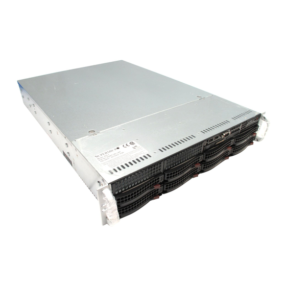
Chapter 1 Introduction Overview The SuperServer 6026T-URF is a high-end server comprised of two main subsys- tems: the SC825TQ-R720UB 2U server chassis and the X8DTU-F dual processor serverboard. Please refer to our web site for information on operating systems that have been certifi... -
Page 10: Serverboard Features
ERVER 6026T-URF User's Manual Serverboard Features At the heart of the SuperServer 6026T-URF lies the X8DTU-F, a dual processor serverboard based on the Intel® 5520 (North Bridge) + ICH10R (South Bridge) chipset. Below are the main features of the X8DTU-F. (See Figure 1-1 for a block diagram of the chipset). -
Page 11: Graphics Controller
BIOS rescue. Server Chassis Features The 6026T-URF is built upon the SC825TQ-R720UB chassis. Details on the chassis and on servicing procedures can be found in Chapter 6. The following is a general outline of the main features of the chassis. -
Page 12: Cooling System
UPER ERVER 6026T-URF User's Manual Cooling System The SC825TQ-R720UB chassis has an innovative cooling design that includes three 8-cm hot-plug system cooling fans located in the middle section of the chassis. An air shroud channels the airfl ow from the system fans to effi ciently cool the processor... -
Page 13: System Block Diagram
Chapter 1: Introduction Figure 1-1. Intel 5520/ICH10R Chipset: System Block Diagram Note: This is a general block diagram. Please see Chapter 5 for details. CPU 1 CPU 2 Port 1 Port 0 Gen2 x16 Gen2 x4 Intel 82576 Ports 7,8,9,10 Ports 1,2 (Lane Reversal) Intel 5520... -
Page 14: Contacting Supermicro
UPER ERVER 6026T-URF User's Manual Contacting Supermicro Headquarters Address: Super Micro Computer, Inc. 980 Rock Ave. San Jose, CA 95131 U.S.A. Tel: +1 (408) 503-8000 Fax: +1 (408) 503-8008 Email: marketing@supermicro.com (General Information) support@supermicro.com (Technical Support) Web Site: www.supermicro.com Europe Address: Super Micro Computer B.V. -
Page 15: Chapter 2 Server Installation
Unpacking the System You should inspect the box the SuperServer 6026T-URF was shipped in and note if it was damaged in any way. If the server itself shows damage you should fi le a damage claim with the carrier who delivered it. -
Page 16: Rack Precautions
UPER ERVER 6026T-URF User's Manual • This product is for installation only in a Restricted Access Location (dedicated equipment rooms, service closets and the like). • This product is not suitable for use with visual display work place devices acccording to §2 of the the German Ordinance for Work with Visual Display Units. -
Page 17: Rack Mounting Considerations
Chapter 2: Server Installation Rack Mounting Considerations Ambient Operating Temperature If installed in a closed or multi-unit rack assembly, the ambient operating tempera- ture of the rack environment may be greater than the ambient temperature of the room. Therefore, consideration should be given to installing the equipment in an environment compatible with the manufacturer’s maximum rated ambient tempera- ture (Tmra). -
Page 18: Installing The System Into A Rack
UPER ERVER 6026T-URF User's Manual Installing the System into a Rack This section provides information on installing the SC825 chassis into a rack unit with the quick-release rails provided. There are a variety of rack units on the market, which may mean the assembly procedure will differ slightly. You should also refer to the installation instructions that came with the rack unit you are using. - Page 19 Chapter 2: Server Installation Figure 2-1: Separating the Rack Rails Separating the Inner and Outer Rails Rail Assembly Locate the rail assembly in the chassis packaging. Extending the Rails Extend the rail assembly by pulling it outward. Press the quick-release tab. Quick- Separate the inner rail extension from Release Tab...
-
Page 20: Outer Rack Rails
UPER ERVER 6026T-URF User's Manual Figure 2-2. Assembling the Outer Rails Outer Rack Rails Outer rails attach to the rack and hold the chassis in place. The outer rails for the SC825 chassis extend between 30 inches and 33 inches. - Page 21 Chapter 2: Server Installation Figure 2-3. Installing the Rack Rails Installing the Chassis into a Rack Extend the outer rails as illustrated above. Align the inner rails of the chassis with the outer rails on the rack. Slide the inner rails into the outer rails, keeping the pressure even on both sides.
-
Page 22: Checking The Serverboard Setup
UPER ERVER 6026T-URF User's Manual Checking the Serverboard Setup After you install the 6026T-URF in the rack, you will need to open the unit to make sure the serverboard is properly installed and all the connections have been made. Accessing the inside of the System First, grasp the two handles on either side and pull the unit straight out until it locks (you will hear a "click"). - Page 23 Chapter 2: Server Installation Figure 2-3. Accessing the Inside of the System...
-
Page 24: Checking The Drive Bay Setup
UPER ERVER 6026T-URF User's Manual Checking the Drive Bay Setup Next, you should check to make sure the peripheral drives and the SAS/SATA drives have been properly installed and all connections have been made. Checking the Drives All drives are accessable from the front of the server. For servicing the DVD- ROM, you will need to remove the top chassis cover. -
Page 25: Chapter 3 System Interface
Chapter 3: System Interface Chapter 3 System Interface Overview There are several LEDs on the control panel as well as others on the drive carri- ers to keep you constantly informed of the overall status of the system as well as the activity and health of specifi... -
Page 26: Control Panel Leds
SUPERSERVER 6026T-URF User's Manual Control Panel LEDs The control panel located on the front of the chassis has several LEDs. These LEDs provide you with critical information related to different parts of the system. This section explains what each LED indicates when illuminated and any corrective action you may need to take. -
Page 27: Hdd
Chapter 3: System Interface On the SuperServer 6026T-URF, this LED indicates hard drive and/or DVD-ROM drive activity when fl ashing. Power Indicates power is being supplied to the system's power supply units. This LED should normally be illuminated when the system is operating. - Page 28 SUPERSERVER 6026T-URF User's Manual Notes...
-
Page 29: Chapter 4 System Safety
System Safety Electrical Safety Precautions Basic electrical safety precautions should be followed to protect yourself from harm and the SuperServer 6026T-URF from damage: • Be aware of the locations of the power on/off switch on the chassis as well as the room's emergency power-off switch, disconnection switch or electrical outlet. -
Page 30: General Safety Precautions
General Safety Precautions Follow these rules to ensure general safety: • Keep the area around the 6026T-URF clean and free of clutter. • The 6026T-URF weighs approximately 57 lbs (25.9 kg.) when fully loaded. When lifting the system, two people at either end should lift slowly with their feet spread out to distribute the weight. -
Page 31: Esd Precautions
Chapter 4: System Safety • After accessing the inside of the system, close the system back up and secure it to the rack unit with the retention screws after ensuring that all connections have been made. ESD Precautions Electrostatic discharge (ESD) is generated by two objects with different electrical charges coming into contact with each other. -
Page 32: Operating Precautions
UPER ERVER 6026T-URF User's Manual Operating Precautions Care must be taken to assure that the chassis cover is in place when the 6026T- URF is operating to assure proper cooling. Out of warranty damage to the system can occur if this practice is not strictly followed. -
Page 33: Chapter 5 Advanced Serverboard Setup
Chapter 5: Advanced Serverboard Setup Chapter 5 Advanced Serverboard Setup This chapter covers the steps required to install processors and heatsinks to the X8DTU-F serverboard, connect the data and power cables and install add-on cards. All serverboard jumpers and connections are described and a layout and quick reference chart are included in this chapter. -
Page 34: Processor And Heatsink Installation
CPU socket cap is in place and none of the socket pins are bent; otherwise, contact your retailer immediately. • Refer to the Supermicro web site for updates on CPU support. Installing LGA1366 Processors Starting with CPU1, press the... - Page 35 Chapter 5: Advanced Serverboard Setup After removing the plastic cap, use your thumb and the index fi nger to hold the CPU at the north and south center edges. Align the CPU key (the semi-circle cutout) with the socket key (the notch below the gold color dot on the side of the socket).
-
Page 36: Installing A Cpu Heatsink
UPER ERVER 6026T-URF User's Manual Installing a CPU Heatsink Remove power from the system and unplug the AC power cord from the power supply. Do not apply any thermal grease to the heatsink or the CPU die; the required amount has already been applied. -
Page 37: Connecting Cables
Chapter 5: Advanced Serverboard Setup Connecting Cables Now that the processors are installed, the next step is to connect the cables to the serverboard. These include the data (ribbon) cables for the peripherals and control panel and the power cables. Connecting Data Cables The cables used to transfer data from the peripheral devices have been carefully routed in preconfi... -
Page 38: I/O Ports
UPER ERVER 6026T-URF User's Manual Figure 5-1. Front Control Panel Header Pins (JF1) Ground x (key) x (key) Power LED HDD LED UID Switch/Vcc NIC1 NIC2 OH/Fan Fail/UID LED Power Fail LED Ground Reset Ground Power I/O Ports The I/O ports are color coded in conformance with the PC 99 specifi cation. See Figure 5-2 below for the colors and locations of the various I/O ports. -
Page 39: Installing Memory
Chapter 5: Advanced Serverboard Setup Installing Memory Note: Check the Supermicro web site for recommended memory modules. CAUTION Exercise extreme care when installing or removing DIMM modules to prevent any possible damage. Installing DIMMs Insert the desired number of DIMMs into the memory slots, starting with slot P1-DIMM1A. - Page 40 UPER ERVER 6026T-URF User's Manual memory allocation to system devices, memory remaining available for operational use will be reduced when 4 GB of RAM is used. The reduction in memory availability is disproportional. (Refer to the Memory Availability Table below for details.) Possible System Memory Allocation &...
-
Page 41: Adding Pci Expansion Cards
Chapter 5: Advanced Serverboard Setup Adding PCI Expansion Cards PCI Expansion Slots One riser card is used to support PCI expansion cards in the system. The RSC- R2UU-UA3E8+ riser card can support one UIO card and three full-height, full-length PCI-Express x8 expansion cards. Installing a PCI Add-on Card Release the locking tab that corresponds to the slot you wish to populate. -
Page 42: Serverboard Details
UPER ERVER 6026T-URF User's Manual Serverboard Details Figure 5-4. SUPER X8DTU-F Layout (not drawn to scale) Fan8 JPW2 (CPU2) P1-DIMM3A JPW3 P1-DIMM3B KB /MS JPW1 P1-DIMM2A P1-DIMM2B JPI2C P1-DIMM1A CPU2 P1-DIMM1B Fan1 Fan2 Battery X8DTU-F CPU1 Fan7 Speaker (CPU1) Fan3... -
Page 43: X8Dtu-F Quick Reference
Chapter 5: Advanced Serverboard Setup X8DTU-F Quick Reference Jumper Description Default Setting JBT1 CMOS Clear (See Section 5-9) C1/JI SMB to PCI-Exp. Slots Open (Disabled) ME Mode Select Open (Normal) ME Recovery Open (Normal) JPG1 VGA Enable/Disable Pins 1-2 (Enabled) JPL1 LAN1/2 Enable/Disable Pins 1-2 (Enabled) -
Page 44: Connector Defi Nitions
UPER ERVER 6026T-URF User's Manual Connector Defi nitions ATX Power 20-pin Connector Pin Defi nitions (JPW1) Pin# Defi nition Pin # Defi nition ATX Power Connector PS On Ground The primary ATX power supply con- 5VSB Ground nector meets the SSI EPS 12V speci-... - Page 45 Chapter 5: Advanced Serverboard Setup HDD LED The HDD (IDE Hard Disk Drive) LED HDD LED Pin Defi nitions (JF1) connection is located on pins 13 and Pin# Defi nition 14 of JF1. Attach the IDE hard drive LED cable to display disk activity. HD Active Refer to the table on the right for pin defi...
- Page 46 UPER ERVER 6026T-URF User's Manual Power Fail LED Power Fail LED Pin Defi nitions (JF1) The Power Fail LED connection is Pin# Defi nition located on pins 5 and 6 of JF1. Refer to the table on the right for pin defi ni- Ground tions.
- Page 47 Chapter 5: Advanced Serverboard Setup Universal Serial Bus Headers Universal Serial Bus Headers Pin Defi nitions (USB2/3, USB4/5) Four additional USB headers (USB2/3 USB2, USB4 USB3, USB5 and USB4/5) are included on the Pin # Defi nition Pin # Defi nition serverboard.
- Page 48 UPER ERVER 6026T-URF User's Manual Power LED/Speaker Speaker Connector Pin Defi nitions (JD1) On the JD1 header, pins 1-3 are for Pin # Function Defi nition a power LED and pins 4-7 are for an Speaker data (red wire) external speaker. See the table on the No connection right for speaker pin defi...
- Page 49 Chapter 5: Advanced Serverboard Setup Power SMB (I C) Connector PWR SMB Pin Defi nitions (JPI The Power System Management Bus Pin# Defi nition C) header (JPI C) is used to moni- Clock tor the power supply, fan and system Data temperatures.
-
Page 50: Jumper Settings
UPER ERVER 6026T-URF User's Manual Jumper Settings Explanation of Jumpers To modify the operation of the serverboard, jumpers can be used Connector to choose between optional settings. Pins Jumpers create shorts between two pins to change the function of the Jumper connector. - Page 51 Chapter 5: Advanced Serverboard Setup LAN Enable/Disable LAN Enable/Disable Change the setting of jumper JPL1 to Jumper Settings (JPL1) enable or disable the onboard Ether- Jumper Setting Defi nition net (RJ45) ports LAN1 and LAN2. See Pins 1-2 Enabled the table on the right for jumper set- Pins 2-3 Disabled tings.
- Page 52 UPER ERVER 6026T-URF User's Manual BMC/PHY Reset Jumper JPRST1 allow the user to reset BMC/PHY Jumper Settings (JPRST1) the Winbond WPCM450 BMC (Base- Jumper Setting Defi nition board Management Controller) chip Closed Reset BMC & PHY and the PHY chip. The default is set...
-
Page 53: 5-10 Onboard Indicators
Chapter 5: Advanced Serverboard Setup 5-10 Onboard Indicators LAN1/LAN2 LEDs The Ethernet ports (located beside the LAN LED Connection Speed Indicator VGA port) have two LEDs. On each LED Color Defi nition Gigabit LAN port, one LED indicates No connection or 10 Mb/s activity when blinking while the other Green 100 Mb/s... -
Page 54: 5-11 Sata Port Connections
UPER ERVER 6026T-URF User's Manual The LE2 LED (located under SW1) is the UID indicator LED. LE2 illuminates when UID is initiated either by the UID button or via IPMI. If initiated a second time, LE2 will turn off. When the LED blinks blue it means the signal was initiated via IPMI. -
Page 55: 5-12 Installing Software
5-12 Installing Software After the hardware has been installed, you should fi rst install the operating system and then the drivers. The necessary drivers are all included on the Supermicro CDs that came packaged with your serverboard. Driver/Tool Installation Display Screen Note: Click the icons showing a hand writing on paper to view the readme fi... -
Page 56: Supero Doctor Iii
UPER ERVER 6026T-URF User's Manual Supero Doctor III The Supero Doctor III program is a Web based management tool that supports re- mote management capability. It includes Remote and Local Management tools. The local management is called SD III Client. The Supero Doctor III program included on the CDROM that came with your serverboard allows you to monitor the environment and operations of your system. - Page 57 Supero Doctor III Interface Display Screen (Remote Control) Note: SD III Software Revision 1.0 can be downloaded from our Web Site at: ftp:// ftp.supermicro.com/utility/Supero_Doctor_III/. You can also download SDIII User's Guide at: http://www.supermicro.com/PRODUCT/Manuals/SDIII/UserGuide.pdf. For Linux, we will still recommend Supero Doctor II.
- Page 58 UPER ERVER 6026T-URF User's Manual Notes 5-26...
-
Page 59: Chapter 6 Advanced Chassis Setup
Chapter 6: Advanced Chassis Setup Chapter 6 Advanced Chassis Setup This chapter covers the steps required to install components and perform main- tenance on the SC825TQ-R720UB chassis. For component installation, follow the steps in the order given to eliminate the most common problems encountered. If some steps are unnecessary, skip ahead to the step that follows. -
Page 60: Control Panel
UPER ERVER 6026T-URF User's Manual Figure 6-1. Front and Rear Chassis Views 3.5" Drive Bays (2) Slim DVD-ROM Drive USB Ports (2) COM Port Control Panel SAS/SATA Drives (8) System Reset Main Power Keyboard/Mouse Ports IPMI LAN 4 Standard Size PCI Slots... -
Page 61: System Fans
Installing a New Fan Replace the failed fan with an identical 8-cm, 12 volt fan (available from Supermicro, p/n FAN-0094L4). Position the new fan into the space vacated by the failed fan previously re- moved. A "click" can be heard when the fan is fully installed in place and the power connections are made. -
Page 62: Drive Bay Installation/Removal
SAS/SATA drives. Proceed to the next step for instructions. You must use standard 1" high, SAS/SATA drives in the system. Note: Refer to the following ftp site for setup guidelines: <ftp://ftp.supermicro.com/ driver/SAS/LSI/LSI_SAS_EmbMRAID_SWUG.pdf> and Supermicro's web site for additional inmformation <... -
Page 63: Sas/Sata Drive Installation
Chapter 6: Advanced Chassis Setup SAS/SATA Drive Installation These drives are mounted in carriers to simplify their installation and removal from the chassis. The carriers also help promote proper airfl ow for the drives. For this reason, even empty carriers without hard drives installed must remain in the chassis. Note: SAS drives are supported only with a SAS UIO controller card installed. -
Page 64: Hard Drive Backplane
UPER ERVER 6026T-URF User's Manual Figure 6-4. Removing a SAS/SATA Drive Carrier Handle Release Button Important: All of the drive carriers must remain in the drive bays to maintain proper cooling airfl ow. Hard Drive Backplane The hard drives plug into a backplane that provides power, drive ID and bus termi- nation. -
Page 65: Dvd-Rom Installation
The top cover of the chassis must be opened to gain full access to the DVD-ROM drive bay. The 6026T-URF accomodates only slim type DVD-ROM drives. Side mounting brackets are typically needed to mount a slim DVD-ROM drive in the server. -
Page 66: Power Supply
The PWR Fail LED will illuminate and remain on until the failed unit has been replaced. Replace- ment units can be ordered directly from Supermicro (see contact information in the Preface). The power supply units have a hot-swap capability, meaning you can replace the failed unit without powering down the system. -
Page 67: Chapter 7 Bios
When an option is selected in the left frame, it is highlighted in white. Often a text message will accompany it. (Note: the AMI BIOS has default text messages built in. Supermicro retains the option to include, omit, or change any of these text messages.) The AMI BIOS Setup Utility uses a key-based navigation system called "hot keys". -
Page 68: Starting The Setup Utility
Warning! Do not upgrade the BIOS unless your system has a BIOS-related issue. Flashing the wrong BIOS can cause irreparable damage to the system. In no event shall Supermicro be liable for direct, indirect, special, incidental, or consequential damages arising from a BIOS update. If you have to update the BIOS, do not shut down or reset the system while the BIOS is updating. - Page 69 Chapter 7: BIOS AMI BIOS • Version : This item displays the BIOS revision used in your system. • Build Date : This item displays the date when this BIOS was complete. Processor The AMI BIOS will automatically display the status of the processor used in your system: •...
-
Page 70: Advanced Setup Confi Gurations
UPER ERVER 6026T-URF User's Manual Advanced Setup Confi gurations Use the arrow keys to select Boot Setup and hit <Enter> to access the submenu items: BOOT Features Quick Boot If Enabled, this option will skip certain tests during POST to reduce the time needed for system boot. -
Page 71: Processor And Clock Options
Chapter 7: BIOS Wait For 'F1' If Error This forces the system to wait until the 'F1' key is pressed if an error occurs. The options are Disabled and Enabled. Hit 'Del' Message Display This feature displays "Press DEL to run Setup" during POST. The options are Enabled and Disabled. - Page 72 UPER ERVER 6026T-URF User's Manual Hardware Prefetcher (Available when supported by the CPU) If set to Enabled, the hardware pre fetcher will pre fetch streams of data and instruc- tions from the main memory to the L2 cache in the forward or backward manner to improve CPU performance.
-
Page 73: Advanced Chipset Control
Chapter 7: BIOS C1E Support Select Enabled to use the feature of Enhanced Halt State. C1E signifi cantly reduces the CPU's power consumption by reducing the CPU's clock cycle and voltage during a "Halt State." The options are Disabled and Enabled. Intel®... - Page 74 UPER ERVER 6026T-URF User's Manual QPI Links Speed This feature selects QPI's data transfer speed. The options are Slow-mode, and Full Speed. QPI Frequency This selects the desired QPI frequency. The options are Auto, 4.800 GT, 5.866GT, 6.400 GT. QPI L0s and L1 This enables the QPI power state to low power.
- Page 75 Chapter 7: BIOS Hysteresis Temperature (This feature is available when Closed Loop is enabled.) Temperature Hysteresis is the temperature lag (in degrees Celsius) after the set DIMM temperature threshold is reached before Closed Loop Throttling begins. The options are Disabled, 1.5 o C, 3.0 C, and 6.0 Guardband Temperature (This feature is available when Closed Loop is enabled.)
- Page 76 UPER ERVER 6026T-URF User's Manual providing the user with greater reliability, security and availability in networking and data-sharing. The options are Enabled and Disabled. SR-IOV Supported Select Enabled to enable Single Root I/O Virtualization (SR-IOV) support which works in conjunction with the Intel Virtualization Technology and allow multiple op- erating systems running simultaneously within a single computer via natively share PCI-Express devices in order to enhance network connectivity and performance.
- Page 77 Chapter 7: BIOS USB Functions This feature allows the user to decide the number of onboard USB ports to be en- abled. The Options are: Disabled, 2 USB ports, 4 USB ports, 6 USB ports, 8 Ports, 10 Ports and 12 USB ports. USB 2.0 Controller This item indicates if the onboard USB 2.0 controller is activated.
- Page 78 UPER ERVER 6026T-URF User's Manual SATA AHCI (Available when the option-AHCI is selected.) Select Enable to enable the function of Serial ATA Advanced Host Interface. (Take caution when using this function. This feature is for advanced program- mers only.) IDE Detect Timeout (sec) Use this feature to set the time-out value for the BIOS to detect the ATA, ATAPI devices installed in the system.
- Page 79 Chapter 7: BIOS PCI-E Slot from SXB1/PCI-E Slot from SXB2/PCI-E Slot from SXB3 Select Enabled to enable PCI-E SXB1 slot, PCI-E SXB2 slot or PCI-E SXB3 slot. It can also enable Option ROMs to boot computer using a network interface from these slots.
-
Page 80: Hardware Health Monitor
UPER ERVER 6026T-URF User's Manual Serial Port Mode This feature allows the user to set the serial port mode for Console Redirection. The options are 115200 8, n 1; 57600 8, n, 1; 38400 8, n, 1; 19200 8, n, 1; and 9600 8, n, 1. - Page 81 ‘Temperature Tolerance’ is, and not the other way around. This results in better CPU thermal management. Supermicro has leveraged this feature by assigning a temperature status to certain thermal conditions in the processor (Low, Medium and High). This makes it easier for the user to understand the CPU’s temperature status, rather than by just simply...
- Page 82 UPER ERVER 6026T-URF User's Manual User intervention: No action is required. However, consider checking the CPU fans and the chassis ventilation for blockage. High – The processor is running hot. This is a ‘caution’ level since the CPU’s ‘Tem- perature Tolerance’ has been reached (or has been exceeded) and may activate an overheat alarm.
- Page 83 Chapter 7: BIOS High Performance Event Timer Select Enabled to activate the High Performance Event Timer (HPET) that produces periodic interrupts at a much higher frequency than a Real-time Clock (RTC) does in synchronizing multimedia streams, providing smooth playback and reducing the de- pendency on other timestamp calculation devices, such as an x86 RDTSC Instruc- tion embedded in the CPU.
- Page 84 UPER ERVER 6026T-URF User's Manual Status of BMC Working The Baseboard Management Controller (BMC) manages the interface between system management software and platform hardware. This item displays the status of the current BMC controller. View BMC System Event Log This feature displays the BMC System Event Log (SEL). It shows the total number of entries of BMC System Events.
- Page 85 Chapter 7: BIOS Set LAN Confi guration Set this feature to confi gure the IPMI LAN adapter with a network address as shown in the following graphics. Channel Number - Enter the channel number for the SET LAN Confi g com- mand.
- Page 86 UPER ERVER 6026T-URF User's Manual SET PEF Confi guration PEF Support Select Enabled to enable the function of Platform Event Filter (PEF) which will interpret BMC events and perform actions based on pre-determined settings or 'traps' under IPMI 1.5 specifi cations. Powering the system down or sending an alert when a triggering event is detected.
-
Page 87: Security Settings
Chapter 7: BIOS BMC Watch Dog TimeOut [Min:Sec] This option appears if BMC Watch Dog Timer Action (above) is enabled. This is a timed delay in minutes or seconds, before a system power down or reset after an operating system failure is detected. The options are [5 Min], [1 Min], [30 Sec], and [10 Sec]. - Page 88 UPER ERVER 6026T-URF User's Manual Supervisor Password This item indicates if a Supervisor password has been entered for the system. "Not Installed" means a Supervisor password has not been used. User Password This item indicates if a user password has been entered for the system. "Not In- stalled"...
-
Page 89: Boot Confi Guration
Chapter 7: BIOS Boot Confi guration Use this feature to confi gure boot settings. Boot Device Priority This feature allows the user to specify the sequence of priority for the Boot Device. The settings are 1st boot device, 2nd boot device, 3rd boot device, 4th boot device, 5th boot device and Disabled. -
Page 90: Exit Options
UPER ERVER 6026T-URF User's Manual Exit Options Select the Exit tab from the Setup Utility screen to enter the Exit screen. Save Changes and Exit When you have completed the system confi guration changes, select this option to leave the BIOS Setup Utility and reboot the computer, so the new system con- fi... -
Page 91: Appendix A Bios Error Beep Codes
Appendix A: BIOS Error Beep Codes Appendix A BIOS Error Beep Codes During the POST (Power-On Self-Test) routines, which are performed each time the system is powered on, errors may occur. Non-fatal errors are those which, in most cases, allow the system to continue the boot-up process. - Page 92 UPER ERVER 6026T-URF User's Manual Notes...
-
Page 93: Appendix B Installing Windows
South Bridge RAID Settings before you install the Windows OS and other software drivers. To confi gure RAID settings, please refer to RAID Confi guration User Guides posted on our web site at www.supermicro.com/support/manuals. B-1 Installing the Windows OS for a RAID System Insert Microsoft's Windows XP/2003/2008/Vista Setup CD in the CD driver, and the system will start booting up from CD. - Page 94 OS Setup will automatically load all device fi les and then continue with the OS installation. After the Windows OS Installation is complete, the system will automatically reboot. Insert the Supermicro Setup CD that came with your serverboard into the CD drive during system boot, and the main screen will display.
-
Page 95: Appendix C System Specifi Cations
Appendix C: System Specifi cations Appendix C System Specifi cations Processors Single or dual Intel® 5500 Series processors in LGA1366 sockets Note: Please refer to our web site for a complete listing of supported processors. Chipset Intel 5520/ICH10R chipset BIOS 32 Mb Award®... - Page 96 UPER ERVER 6026T-URF User's Manual Chassis SC825TQ-R720UB (2U rackmount) Dimensions: (WxHxD) 16.8 x 3.5 x 25.5 in. (427 x 89 x 648 mm) Weight Gross (Bare Bone): 57 lbs. (25.9 kg.) System Cooling Three 8-cm system cooling fans System Input Requirements...
- Page 97 Appendix C: System Specifi cations Notes...
- Page 98 ERVER 6026T-URF User's Manual (continued from front) The products sold by Supermicro are not intended for and will not be used in life support systems, medical equipment, nuclear facilities or systems, aircraft, aircraft devices, aircraft/emergency com- munication devices or other critical systems whose failure to perform be reasonably expected to result in signifi...
Need help?
Do you have a question about the SuperServer 6026T-URF and is the answer not in the manual?
Questions and answers