Table of Contents
Advertisement
Quick Links
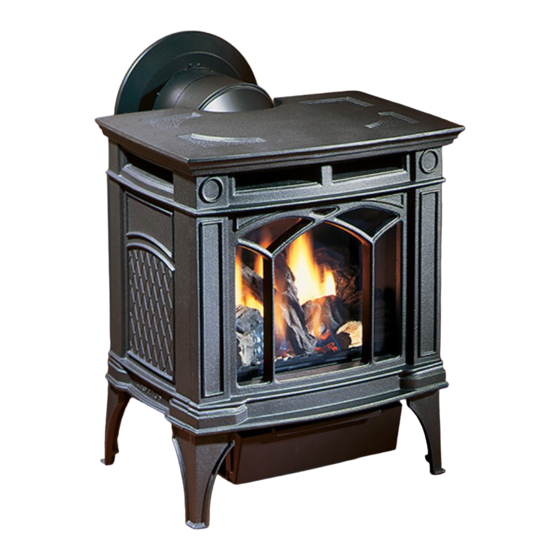
H15 Direct Vent Gas Fireplace
WARNING:
If the information in these instructions are not
followed exactly, a fi re or explosion may result
causing property damage, personal injury or loss
of life.
FOR YOUR SAFETY
Do not store or use gasoline or other fl ammable
vapours and liquids in the vicinity of this or any
other appliance.
Installation and service must be performed by
a qualifi ed installer, service agency or the gas
supplier.
Tested by:
918-516a
FPI FIREPLACE PRODUCTS INTERNATIONAL LTD. 6988 Venture St., Delta, BC Canada, V4G 1H4
www.hampton-fi re.com
MODELS:
H15-NG1 Natural Gas
FOR YOUR SAFETY
What to do if you smell gas:
Do not try to light any appliance
Do not touch any electrical switch:
do not use any phone in your
building.
Immediately call your gas supplier
from a neighbour's phone. Follow
the gas supplier's instructions.
If you cannot reach your gas sup-
plier, call the fi re department.
Installer: Please complete the details on the back cover
and leave this manual with the homeowner.
Homeowner: Please keep these instructions for future reference.
Installation Manual
H15-LP1 Propane
This appliance may only be
installed in an aftermarket
permanently located, manu-
factured (USA only) or mobile
home, where not prohibited by
local codes.
This appliance is only for use
with the type of gas indicated
on the rating plate. This ap-
pliance is not convertible for
use with other gases, unless
a certifi ed kit is used.
Owners &
12/17/07
Advertisement
Table of Contents

Subscribe to Our Youtube Channel
Related Manuals for HAMPTON BAY H15-LP1


Summary of Contents for HAMPTON BAY H15-LP1
- Page 1 Installer: Please complete the details on the back cover and leave this manual with the homeowner. Homeowner: Please keep these instructions for future reference. Owners & Installation Manual H15-LP1 Propane This appliance may only be installed in an aftermarket permanently located, manu- factured (USA only) or mobile home, where not prohibited by local codes.
-
Page 2: Unit Dimensions
HAMPTON ® Direct Vent Freestanding Gas Stove To the New Owner: Congratulations! You are the owner of a state-of-the-art Hampton ® Gas Stove by FPI FIREPLACE PRODUCTS INTERNATIONAL LTD. The H15-1 is a hand crafted appliance and has been designed to provide you with all the warmth and charm of a wood fi... -
Page 3: Table Of Contents
SAFETY LABEL Safety Label ...4 REQUIREMENTS MA Code - CO Detector ...5 INSTALLATION Important Message ...6 Specifi cations ...6 Mobile / Manufactured Homes After First Sale ...6 Before You Start ...6 General Safety Information ...7 Installation Checklist ...7 Clearances to Combustibles ...7 Locating Your Gas Stove ...8 Manufactured Mobile Home Additional Requirements ..8 Combustion and Ventilation Air ...8... -
Page 4: Safety Label
SAFETY LABEL This is a copy of the label that accompanies each Direct Vent Freestanding Gas Stove. We have printed a copy of the contents here for your review. For the State of Massachusetts, installation and repair must be done by a plumber or gasfi tter licensed in the Commonwealth of Massachusetts. For the State of Massachusetts, fl... -
Page 5: Requirements
REQUIREMENTS MA Code - CO Detector (for the State of Massachusetts only) 5.08: Modifications to NFPA-54, Chapter 10 (2) Revise 10.8.3 by adding the following additional requirements: (a) For all side wall horizontally vented gas fueled equipment installed in every dwelling, building or structure used in whole or in part for residential purposes, including those owned or operated by the Commonwealth and where the side wall exhaust vent termination is less than seven (7) feet above finished grade in the area of the venting, including but not limited to decks and porches, the following requirements shall be satisfied:... -
Page 6: Installation
SPECIFICATIONS Fuels: H15-NG1 is approved for use with natural gas. H15-LP1 is approved for use with liq- uefi ed petroleum gases (propane). Electrical: 120V A.C. system. Optional Circulation Fan: Variable speed, 125/75. Log Sets: Ceramic fi bre, 4 per set. -
Page 7: General Safety Information
fl oor. This unit can also be installed directly on carpeting or vinyl. Use the minimum clearances shown in the diagrams below: H15-NG1 & H15-LP1 Clearances A Left Side Wall to Unit* 6" / 150 mm *B Back Wall to Unit 0"... -
Page 8: Locating Your Gas Stove
INSTALLATION LOCATING YOUR GAS STOVE When selecting a location for your stove, ensure that the clearances listed above are met as well as ensuring that there is adequate accessibility for servicing and proper operation. * 12' max. only if vertical height is achieved. Cross Corner Room Divider Island... - Page 9 9) Remove 2 screws from unit. 10) Place grommet in rear plate through the bottom of the opening as shown below. Rear Plate Grommet 11) Place the blower close to the base of the unit and feed the wires through the grommet in the rear plate.
-
Page 10: Venting Introduction
Dura-Vent Direct Vent System Model DV-GS venting systems, in combination with the Direct Vent Freestanding Gas Stoves, H15-NG1, and H15-LP1, have been tested and listed as direct vent heater systems by Warnock Hersey. These units use the "balanced fl ue" technology Co-Axial system. -
Page 11: Exterior Vent Terminal Locations
INSTALLATION EXTERIOR VENT TERMINAL LOCATIONS ® Hampton H15-1 Direct Vent Freestanding Gas Stove... -
Page 12: 4" X 6-5/8" Rigid Pipe Cross Reference Chart
INSTALLATION 4” X 6-5/8” RIGID PIPE CROSS REFERENCE CHART Components from different Manufacturers may not be mixed. Not All Rigid Pipe components are available directly from FPI. Description 6” Pipe Length, Galvanized 6” Pipe Length, Black 7” Pipe Length, Galvanized 7”... - Page 13 4” x 6-5/8” Rigid Pipe Cross Reference Chart (Cont.) Components from different Manufacturers may not be mixed. Not All Rigid Pipe components are available directly from FPI. Description Attic Insulation Shield 12” Attic Insulation Shield - 36” Cold Climates Basic Horizontal Termination Kit (A) Horizontal Termination Kit (B) Vertical Termination Kit High Wind Vertical Cap...
-
Page 14: Rigid Pipe Venting Systems
INSTALLATION Alternate Horizontal Termination Caps WARNING: Do not combine venting components from different venting systems. However use of the the AstroCap and FPI Riser is acceptable with all systems. This product has been evaluated by Intertek for using a Rigid Pipe Adaptor in conjunction with Duravent Direct-Vent GS, Selkirk Direct-Temp, Ameri Vent Direct venting and Security Secure Vent systems. - Page 15 One 90 elbow = Two 45 Option H + H1 With these options, maxi- 1' Min. 3' Max. mum total pipe length is 30 2' Min. 4' Max. feet with minimum of 6 feet total vertical and maximum 3' Min. 5' Max.
- Page 16 INSTALLATION One 90 elbow = Two 45 Option V V + V1 With these options, max. total pipe length is 30 feet with min. 1' Min. 4' Max. 2' Min. of 6 feet total vertical and max. 2' Min. 5' Max. 3' Min. 8 feet total horizontal.
-
Page 17: Venting Arrangements
Horizontal Terminations for All Venting Systems The shaded areas in the diagram below show all allowable combinations of vertical runs with hori- zontal terminations. Maximum one 90 elbows equal one 90 elbow). Propane and Natural Gas: Residential, Manufactured and Mobile Homes Installations May be installed in Manufactured (Mobile) Homes after fi... -
Page 18: Vertical Termination With Co-Linear Flex System
INSTALLATION VERTICAL TERMINATION WITH CO-LINEAR FLEX SYSTEM THE APPLIANCE MUST NOT BE CONNECTED TO A CHIMNEY FLUE SERVING A SEPARATE SOLID FUEL BURNING APPLIANCE. This appliance is designed to be attached to two 3" (76mm) co-linear aluminium fl ex running the full length of the chimney. -
Page 19: Dv Stove Horizontal Vent Kit
DV STOVE HORIZONTAL VENT KIT DV 2 ft. Stove Vent Kit (Part # 946-116) and DV 4 ft. Stove Vent Kit (946-216) includes all the parts needed to install the H15-1 Direct Vent unit with up & out horizontal and vertical vent dimensions. For installations that require longer vertical and/or horizontal vents use the Dura-Vent system as shown in the "Dura-Vent Termina- tion Kit"... - Page 20 INSTALLATION 3) Attach the 4" dia. fl ex liner to the vent ter- minal ensuring that the fl ex overlaps the collar of the vent terminal by a minimum of 1-3/8"(35mm). Use Mill-Pac to seal and secure with 3 of the #8 x 1/2" screws (stainless steel).
-
Page 21: Residential And Manufactured Homes / Mobile Homes
RESIDENTIAL AND MANUFACTURED HOMES / MOBILE HOMES MINIMUM HORIZONTAL TERMINATION INSTALLATIONS Planning Your Venting Installation See the "Exterior Vent Terminal Locations" section for requirements. When planning your installation, it will be nec- essary to select the proper length of vent pipe for your particular requirements. -
Page 22: Dura-Vent Termination Kit
INSTALLATION Planning Your Dura-Vent Installation There are two basic types of Dura-Vent Direct Vent System installations: horizontal termination and vertical termination. Confi rm the maximum horizontal run and maximum vertical rise from the diagrams in the "Rigid Pipe Venting Sys- tems"... -
Page 23: Horizontal Terminations
You will require the following components with your new Direct Vent Freestanding Gas Stove. Please review your product to make sure you have everything you need. In the event that you are missing any part, contact your dealer. Note: These are the minimum pieces re- quired. -
Page 24: Vertical Terminations
INSTALLATION Diagram 4 7) Install the Backing Plate into the wall penetra- tion heat shield and attach using 4 screws. Dia. 4. 8) Connect all pipe sections to unit and install into wall: a) Measure pipe length required and cut to length. - Page 25 Diagram 8 3) To install the Round Support Box/Wall Thim- ble in a fl at ceiling, cut a 10 inch square hole in the ceiling centred on the hole drilled in Step 2. Frame the hole as shown in diagram Diagram 9 4) Assemble the desired lengths of black pipe and elbows necessary to reach from the...
-
Page 26: Converting Class-A Metal Chimney Or Masonry Chimney To Direct Vent System
INSTALLATION CONVERTING CLASS-A METAL CHIMNEY OR MASONRY CHIMNEY TO DIRECT VENT SYSTEM There are two different types of direct vent conversion systems listed below. Follow the appropriate directions for your installation. A) Through an existing factory built metal chimney going through the ceiling: A typical conversion of this type is shown in diagram 1. -
Page 27: Cathedral Ceilings
Min. Input Rating 10,500 Btu/h Supply Pressure min.5.0" w.c. Manifold Pressure (High) 3.8"+/- 0.2"w.c. H15-LP1 System Data Conversion Kit# 380-969 For 0 to 2000 feet altitude Burner Inlet Orifi ce Sizes: Max. Input Rating 18,000 Btu/h Min. Input Rating 10,600 Btu/h For 2000 to 4500 feet altitude Burner Inlet Orifi... -
Page 28: Aeration Adjustment
INSTALLATION AERATION ADJUSTMENT The air shutter can be adjusted by moving the adjusting wire up or down. The wire is accessed through the bottom. Open the air shutter for a blue fl ame or close for a yellower fl ame. The burner aeration is factory set but may need adjusting due to either the local gas supply or altitude. -
Page 29: Conversion Kit# 381-969 From Ng To Lp
CONVERSION KIT# 381-969 FROM NG TO LP THIS CONVERSION MUST BE DONE BY A QUALIFIED GAS FITTER IF IN DOUBT DO NOT DO THIS CONVERSION !! Each Kit contains one LPG Conversion Kit and one DC Sparker Kit. LPG Conversion Kit Contains: Qty. -
Page 30: Installation Of The Dc Sparker
INSTALLATION 11) Reassemble the black protection cap (Fig. 6). Fig. 6 WARNING! Also check that the pilot and main burner injectors are appropriate for the gas type. 12) Pull off the pilot cap to expose the pilot orifi ce. 13) Unscrew the pilot orifi ce with the allen key and replace with the LP pilot orifi... - Page 31 25) Attach the Piezo ignition wire to the DC Sparker. Piezo Ignitor 26) Insert both the ground wire and the DC sparker generator wire through the hole of the DC spark heat shield. 27) Install the plastic bushing over the outside of the hole.
-
Page 32: Log Set Installation
INSTALLATION Read the instructions below carefully and refer to the diagrams. If the logs are broken do not use the unit until they are replaced. Broken logs can interfere with the pilot operation. The gas log kit contains the following: a) Rear Log b) Left Side Front Log c) Right Side Front Log... - Page 33 8) Take the embers and place on the burner in the space between the 2 front logs, ensure not to cover any burner ports. Do not put embers on the burner in the area between the front logs and the rear log. See photo below.
-
Page 34: Optional Wall Thermostat
INSTALLATION OPTIONAL WALL THERMOSTAT A wall thermostat may be installed if desired. Connect the wires as per the wiring diagrams. Note that the wires are connected to the "TH" on the gas valve. Use table below to determine the maximum wire length: Note: Preferable if the thermostat is installed on an interior wall. -
Page 35: Wiring Diagrams
If any of the original wires as supplied with the appliance must be replaced, it must be replaced with CSA type SEW (200 C) or its equivalent. This heater does not require a 120V A.C. sup- ply for operation. In case of a power failure, the burner switch and the optional remote control/ thermostat will continue to operate. - Page 36 INSTALLATION PROPANE Units and Units Equipped with DC Spark Boxes* *For installation of the DC Spark Box refer to the LP Conversion instructions in this manual. ® Hampton H15-1 Direct Vent Freestanding Gas Stove...
-
Page 37: Operating Instructions
OPERATING INSTRUCTIONS 1) Read and understand these instructions before operating this appliance. 2) Check to see that all wiring is correct and enclosed to prevent possible shock. 3) Check to ensure there are no gas leaks. 4) Make sure the glass in the door frame is properly positioned. -
Page 38: Copy Of The Lighting Plate Instructions
OPERATING INSTRUCTIONS COPY OF THE LIGHTING PLATE INSTRUCTIONS FOR YOUR SAFETY READ BEFORE LIGHTING This appliance must be installed in accordance with local codes, if any; if none, follow the National Fuel Gas Code, ANSI Z223.1/ NFPA 54, or Natural Gas and Propane Installation Codes, CSA B149.1. (Australia: AS5601-2004, New Zealand: NZS 5261) WARNING: If you do not follow these instructions exactly, a fi... -
Page 39: Maintenance
NORMAL OPERATING SOUNDS OF GAS APPLIANCES It is possible that you will hear some sounds from your gas appliance. This is perfectly normal due to the fact that there are various gauges and types of steel used within your appliance. Listed below are some examples. -
Page 40: Fan Maintenance
MAINTENANCE GENERAL VENT MAINTENANCE Conduct an inspection of the venting system semi-annually. Recommended areas to inspect as follows: 1) Check the Venting System for corrosion in areas that are exposed to the elements. These will appear as rust spots or streaks, and in extreme cases, holes. -
Page 41: Removing Valve
REMOVING VALVE If your valve requires maintenance or replace- ment, use the following instructions: Note: Always close off the gas supply before removing the valve. 1) If optional fan is installed, disconnect power source to stove. 2) Remove access panel. 3) Disconnect gas line to stove. -
Page 42: Parts List
PARTS LIST Part # Description 942-601** Casting - Top 942-621** Casting - Side & Leg 942-611** Casting - Front 770-066F Top Relief Plate W260280 Top Relief Plate Gasket 770-067F Plate Insulation Holder 942-117 Top Relief Frame W260260 Top Relief Frame Gasket 945F Dura-Vent Collar W842051... -
Page 43: Burner & Log Assembly
Part # Description 380-574/P Valve/Pilot Assembly - S.I.T. - NG 910-478 Valve S.I.T. - NG/LPG 904-434 #47 Orifi ce - NG 910-190 Piezo Ignitor & Nut 908-672 Control Panel Decal 490-061 Switch Plate 936-170 Orifi ce Gasket 910-038 Pilot Assy-S.I.T. - 3 fl ame - NG 910-039 Pilot Assy-S.I.T. - Page 44 NOTES ___________________________________________________ ___________________________________________________ ___________________________________________________ ___________________________________________________ ___________________________________________________ ___________________________________________________ ___________________________________________________ ___________________________________________________ ___________________________________________________ ___________________________________________________ ___________________________________________________ ___________________________________________________ Hampton ® H15-1 Direct Vent Freestanding Gas Stove...
- Page 45 NOTES ___________________________________________________ ___________________________________________________ ___________________________________________________ ___________________________________________________ ___________________________________________________ ___________________________________________________ ___________________________________________________ ___________________________________________________ ___________________________________________________ ___________________________________________________ ___________________________________________________ ___________________________________________________ ® Hampton H15-1 Direct Vent Freestanding Gas Stove...
- Page 46 NOTES ___________________________________________________ ___________________________________________________ ___________________________________________________ ___________________________________________________ ___________________________________________________ ___________________________________________________ ___________________________________________________ ___________________________________________________ ___________________________________________________ ___________________________________________________ ___________________________________________________ ___________________________________________________ ® Hampton H15-1 Direct Vent Freestanding Gas Stove...
-
Page 47: Warranty
WARRANTY Hampton Fireplace Products are designed with reliability and simplicity in mind. In addition, our internal Quality Assurance Team carefully inspects each unit thoroughly before it leaves our facility. FPI Fireplace Products International Ltd. is pleased to extend this limited lifetime warranty to the original purchaser of a Hampton Product. - Page 48 Hampton reliability and simplicity in mind. In addition, our internal Quality Assurance Team carefully inspects each unit thoroughly before it leaves our door. FPI Fireplace Products International Ltd. is pleased to extend this Limited Lifetime Warranty to the original purchaser of a Hampton See the inside back cover for details.
Need help?
Do you have a question about the H15-LP1 and is the answer not in the manual?
Questions and answers