Table of Contents
Advertisement
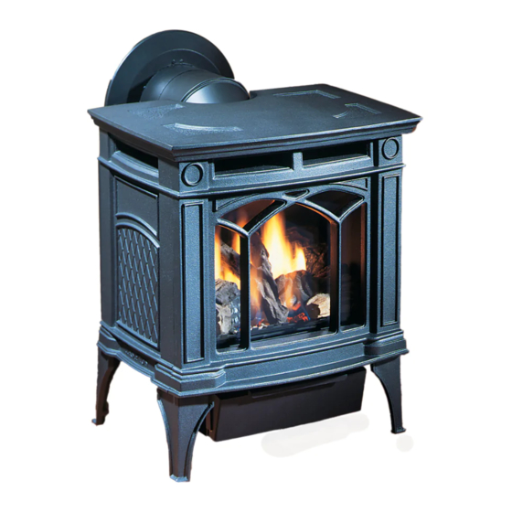
H15 Direct Vent Gas Fireplace
MODELS:
H15-NG10 Natural Gas
WARNING
FIRE OR EXPLOSION HAZARD
Failure to follow safety warnings exactly could result in serious
injury, death, or property damage.
- Do not store or use gasoline or other flammable vapors and liquids in the vicinity of this or any other
appliance.
- WHAT TO DO IF YOU SMELL GAS
• Do not try to light any appliance.
• Do not touch any electrical switch: do not use any phone in your building.
Leave the building immediately.
• Immediately call your gas supplier from a neighbour's phone. Follow the gas supplier's
instructions.
• If you cannot reach you gas supplier, call the fire department.
Installation and service must be performed by a qualified installer, service agency or the gas supplier.
Tested by:
FPI FIREPLACE PRODUCTS INTERNATIONAL LTD. 6988 Venture St., Delta, BC Canada, V4G 1H4
919-446d
H15-LP10 Propane
Installer: Please complete the details on the back cover
and leave this manual with the homeowner.
Homeowner: Please keep these instructions for future reference.
Owners &
Installation Manual
www.hampton-fire.com
04.26.17
Advertisement
Table of Contents

Related Manuals for HAMPTON BAY H15-NG10


Summary of Contents for HAMPTON BAY H15-NG10
- Page 1 Owners & H15 Direct Vent Gas Fireplace Installation Manual www.hampton-fire.com MODELS: H15-NG10 Natural Gas H15-LP10 Propane WARNING FIRE OR EXPLOSION HAZARD Failure to follow safety warnings exactly could result in serious injury, death, or property damage. - Do not store or use gasoline or other flammable vapors and liquids in the vicinity of this or any other appliance.
- Page 2 HAMPTON ® Direct Vent Freestanding Gas Stove To the New Owner: Congratulations! You are the owner of a state-of-the-art Hampton Gas Stove by FPI FIREPLACE PRODUCTS INTERNATIONAL LTD. ® The H15-10 is a hand crafted appliance and has been designed to provide you with all the warmth and charm of a wood fireplace at the flick of a switch.
-
Page 3: Table Of Contents
dimensions Dimensions Gas Pipe Pressure Testing ..........31 885 S.I.T. Valve Description .........31 Unit Dimensions with horizontal vent......4 Conversion from Ng to LP ...........32 Unit Dimensions with vertical vent .........5 Log Set Installation ............33 Optional Wall Thermostat ...........35 Installation Back up battery............35 Remote/Receiver coding ..........35 Important Message ............8 Manual operation(no remote) ........35... -
Page 4: Dimensions
dimensions UNIT DIMENSIONS WITH HORIZONTAL VENT 20-11/16" (525mm) 19-1/8" (485mm) 14-1/4 (361mm) 19-3/8" 13-5/8" (492mm) (345mm) ALL PICTURES / DIAGRAMS SHOWN THROUGHOUT THIS MANUAL ARE FOR ILLUSTRATION PURPOSES ONLY. ACTUAL PRODUCT MAY VARY DUE TO PRODUCT ENHANCEMENTS. Hampton® H15-10 Direct Vent Freestanding Gas Stove... -
Page 5: Unit Dimensions With Vertical Vent
dimensions UNIT DIMENSIONS WITH VERTICAL VENT Hampton® H15-10 Direct Vent Freestanding Gas Stove... - Page 6 Certified to: CSA 2.33-2014 4001172 MAY BE INSTALLED IN MANUFACTURED (MOBILE) HOMES AFTER FIRST SALE. APPAREIL FONCTIONNANT AU GAZ NATUREL NATURAL GAS STOVE: Model H15-NG10 Minimum Clearances to Combustibles / Modèle H15-NG10 Dégagements minimaux 5" WC/C.E. (1.25 kPa) Minimum supply pressure Pression d’alimentation minimum...
- Page 7 requirements MA Code - CO Detector (for the State of Massachusetts only) 5.08: Modifications to NFPA-54, Chapter 10 (2) Revise 10.8.3 by adding the following additional requirements: (a) For all side wall horizontally vented gas fueled equipment installed in every dwelling, building or structure used in whole or in part for residential purposes, including those owned or operated by the Commonwealth and where the side wall exhaust vent termination is less than seven (7) feet above finished grade in the area of the venting, including but not limited to decks and porches, the following requirements shall be satisfied:...
-
Page 8: Installation
PHYSICAL BARRIERS IS RECOMMEND- with other gases, unless a certified kit ED IF THERE ARE AT RISK INDIVIDUAL Fuels: H15-NG10 is approved for use with is used. IN THE HOUSE. TO RESTRICT ACCESS natural gas. TO A FIREPLACE OR STOVE, INSTALL... -
Page 9: General Safety Information
installation 1) Provide adequate clearances for servicing, cleaning may be required due to excessive a. Log Set Installation lint from carpeting, bedding material, etc. It b. Wall Thermostat proper operation and around the air openings is imperative that control compartments, and c. -
Page 10: Clearances To Combustibles
Use the minimum clearances shown in the dia- Flat on Wall grams below: Flat on Wall Corner Flush with Wall/Alcove H15-NG10 & H15-LP10 Clearances A Left Side Wall to Unit* 6" / 150 mm For Vent Termination requirements, see the "Exterior Vent Terminal Locations" section. -
Page 11: Optional Fan Installation
installation OPTIONAL FAN OPTIONAL FAN INSTALLATION INSTALLATION Tuck the fan assembly in behind the legs Remove left side access panel (when as shown. On either side of the unit there facing front) by removing one screw. will be slits located on the body of the Remove the rear access panel on the back of stove. -
Page 12: Glass Door
installation GLASS FRONT WALL THERMOSTAT REMOVAL / INSTALLATION INSTALLATION 1. Turn off stove and allow to return to room tem- 5. Lift both latches securing glass door and 1. Open the front panel and remove the cover perature. remove door. plate by removing two screws. -
Page 13: Venting Introduction
Stoves, H15-NG10, and H15-LP10, have been the H15-NG10, and H15-LP10. The warranty will tested and listed as direct vent heater systems by be voided and serious fire, health or other safety 2) Exercise extreme caution when using lad- Warnock Hersey. -
Page 14: Exterior Vent Terminal Locations
installation EXTERIOR VENT TERMINAL LOCATIONS Minimum Clearance Requirements Canada Clearance above grade, veranda, porch, deck, or balcony 12"(30cm) 12"(30cm) Clearance to window or door that may be opened 12"(30cm) 9" (23cm) Clearance to permanently closed window Vertical clearance to ventilated soffit located above the terminal within a horizontal distance of 2 feet (61cm) 22"(56cm) 22"(56cm) from the center line of the terminal (check with the local code) -
Page 15: 4" X 6-5/8" Rigid Pipe
installation 4” X 6-5/8” RIGID PIPE CROSS REFERENCE CHART Components from different Manufacturers may not be mixed. Not All Rigid Pipe components are available directly from FPI. 4” X 6- ” RIGID PIPE CROSS REFERENCE CHART Components from different Manufacturers may not be mixed. Not all rigid pipe components are available directly from Regency. Note: The listed manufacturers may have other lengths not shown on this chart, which would also be approved. - Page 16 installation Description Selkirk American Metal Security ICC Excel Olympia Simpson Metal-Fab™ Ventis DV* Direct Temp™ Products® Secure- Vent® Direct Direct Vent Pro ® Sure Seal Amerivent Direct Attic Insulation Shield 12” 46DVA-IS 4DAIS12 SV4RSA VDV-AIS04 N/A@ FPI Attic Insulation Shield 4DAIS12 TM-4AS - Cold Climates 36”...
-
Page 17: Rigid Pipe Venting Systems
installation RIGID PIPE VENTING SYSTEMS Horizontal or Vertical Terminations Alternate Vertical Horizontal Termination Termination Max. Caps Storm Collar Vinyl Siding Standoff (Optional) Flashing Horizontal Termination Ceiling Firestop Wall Thimble Pipe Length Adj.Pipe Length 11" - 14-5/8" 90 Elbow WARNING: Do not combine venting components from 24"... - Page 18 installation Horizontal Venting with Two (2) 90 Elbows One 90 elbow = Two 45 elbows. Option H + H1 With these options, maxi- 1' Min. 3' Max. mum total pipe length is 30 2' Min. 4' Max. feet with minimum of 6 feet total vertical and maximum 3' Min.
- Page 19 installation Vertical Venting with Two (2) 90 Elbows One 90 elbow = Two 45 elbows. Option V V + V1 With these options, max. total pipe length is 30 feet with min. 1' Min. 4' Max. 2' Min. of 6 feet total vertical and max. 2' Min.
-
Page 20: Venting Arrangements
installation VENTING ARRANGEMENTS Horizontal Terminations for Vertical Terminations Systems for All Venting Systems Residential Manufactured and Mobile Homes The shaded areas in the diagram below show all The shaded area in the diagram below shows all allowable combinations of straight allowable combinations of vertical runs with hori- vertical and offset to vertical runs with vertical terminations. -
Page 21: Vertical Termination With Co-Linear Flex System
installation VERTICAL TERMINATION WITH CO-LINEAR FLEX SYSTEM Masonry chimneys may take various contours which the flexible liner will accommodate. However, keep THE APPLIANCE MUST NOT BE CONNECTED TO A CHIMNEY FLUE the flexible liner as straight as possible, avoid unnecessary bending. SERVING A SEPARATE SOLID FUEL The Air Intake pipe must be attached to the inlet air collar of the termination cap. -
Page 22: Dv Stove Horizontal Vent Kit
installation DV STOVE HORIZONTAL VENT KIT DV 2 ft. Stove Vent Kit (Part # 946-116) and DV 4 ft. Stove Vent Kit (946-216) includes all the parts needed to install the H15-10 Direct Vent unit with up & out horizontal and vertical vent dimensions. For installations that require longer vertical and/or horizontal vents use the Dura-Vent system as shown in the "Dura-Vent Termina- tion Kit"... - Page 23 installation 10) Slide the decorative Thimble Cover over the pipe sections and secure with 4 screws (#8 x 1-1/2" drill point, black) to the wall. 11) Slide the 90 elbow (crimp end up), the 45 elbow and the 4 ft. pipe section (crimp end up) over the 4"...
-
Page 24: Residential And Manufactured Homes / Mobile Homes
installation RESIDENTIAL AND MANUFACTURED HOMES / MOBILE HOMES MINIMUM HORIZONTAL TERMINATION INSTALLATIONS Planning Your Venting Installation new Hampton ® Direct Vent Freestanding Gas Stove. Please review your product to make sure you have See the "Exterior Vent Terminal Locations" everything you need. In the event that you are missing any part, contact your dealer. Decorative brass section for requirements. -
Page 25: Dura-Vent Termination Kit
installation DURA-VENT TERMINATION KIT Planning Your Dura-Vent Installation tion.) Select the amount of vertical rise desired in the "Exterior Vent Terminal Locations" section for "vertical-to-horizontal" type installations. and in your local building codes. There are two basic types of Dura-Vent Direct Warning: Always maintain required Vent System installations: horizontal termination To determine the length of vent pipe required... -
Page 26: Horizontal Terminations
installation Please review your product to make sure you have everything you need. In the event that you are missing any part, contact your dealer. Note: These are the minimum pieces required. Other parts may be required for your particular installation. See above for a list of vent parts. -
Page 27: Vertical Terminations
installation c) Before connecting the vent pipe to the vent termination, slide the black decorative wall thimble cover over the vent pipe, then slide the Wall Penetration Heat Shield over the vent pipe. Dia. 3. d) Slide the appliance and vent assembly towards the wall carefully inserting the vent pipe into the riser vent terminal assembly. -
Page 28: Offset Chart
installation 7) Ensure vent is vertical and secure the base of the flashing to the roof with roofing rails, slide storm collar over the pipe section and seal with a mastic. 8) Install the vertical termination cap by twist locking it. Notes: a) For multistorey vertical installations, a Ceiling Fire stop is required at the... -
Page 29: Converting Class-A Metal Chimney To Direct Vent System
installation CONVERTING CLASS-A METAL CHIMNEY TO DIRECT VENT SYSTEM Prior to installation and connection of the vent system to a factory-built or masonry chimney, the chimney must be inspected and thoroughly cleaned by a qualified service person, such as a certified chimney sweep or home inspection service. -
Page 30: Cathedral Ceilings
2) Place the support in the opening. Lower it to Steep pitched cathedral ceilings may require the the correct height as determined by the table H15-NG10 System Data use of a support extension. This piece fits down and diagram below. -
Page 31: Aeration Adjustment
installation AERATION GAS PIPE 885 S.I.T. VALVE ADJUSTMENT PRESSURE TESTING DESCRIPTION The appliance must be isolated from the gas sup- 1) 6 Stage flame adjustment The air shutter can be adjusted by moving the adjust- 2) Pilot adjustment ply piping system by closing its individual manual ing wire up or down. -
Page 32: Conversion From Ng To Lp
installation CONVERSION FROM NG TO LP CONVERSION FROM NG TO LP THIS CONVERSION MUST BE DONE BY A QUALIFIED GAS FITTER IF IN DOUBT DO NOT DO THIS CONVERSION !! Unscrew the pilot orifice with the allen key 11. Remove NG stepper motor by remov- Each Kit contains one LPG and replace with the LP pilot orifice in the ing 2 screws in locations shown below. -
Page 33: Log Set Installation
installation LOG SET INSTALLATION LOG SET INSTALLATION Read the instructions below carefully and refer to the 5) Carefully remove the logs from the unit and diagrams. If the logs are broken do not use the unit unwrap them. The logs are fragile, handle with until they are replaced. - Page 34 LOG SET INSTALLATION installation 8) Take the embers and place on the burner in the 9) Place the center cross log on the top of the rear log space between the 2 front logs, ensure not to cover and position as shown below. any burner ports.
-
Page 35: Optional Wall Thermostat
installation OPTIONAL BACK UP BATTERY 5. Hold down the ON/OFF button on the hand held remote to code the remote to the re- WALL THERMOSTAT ceiver–after 4 beeps are heard–handheld is In the event of a power outage the unit may be paired with receiver. -
Page 36: Wiring Diagram Without Thermostat
installation WIRING DIAGRAM WITHOUT THERMOSTAT This heater does not require a 120V A.C. supply WARNING: CAUTION: Ensure that the wires for operation. In case of a power failure, the re- Electrical Grounding do not touch a hot surface and are mote control/thermostat will continue to operate. -
Page 37: Wiring Diagram With Thermostat
operating instructions WIRING DIAGRAM WITH THERMOSTAT Thermostat (Optional) (Millivolt) Hampton® H15-10 Direct Vent Freestanding Gas Stove... -
Page 38: Lighting Procedure
operating instructions FIRST FIRE - The stove can now be operated with the ON/OFF This remote control requires coding. See remote switch located on the front of the valve tray cover. coding instructions for details. The burner will remain lit until the switch is moved The first fire in your stove is part of the paint curing to the OFF position. -
Page 39: Lighting Procedure
operating instructions LIGHTING PROCEDURE IMPORTANT: The remote control system supplied with this appliance has Note: The first try for ignition will last approximately 60 seconds. If there is no several options for starting/operating the appliance using the power button flame ignition (rectification) the board will stop sparking for approximately and ON/OFF key on the hand held transmitter. -
Page 40: Copy Of The Lighting Plate Instructions
operating instructions COPY OF THE LIGHTING PLATE INSTRUCTIONS FOR YOUR SAFETY READ BEFORE LIGHTING This appliance must be installed in accordance with local codes, if any; if none, follow the National Fuel Gas Code, ANSI Z223.1/NFPA 54, or Natural Gas and Propane Installation Codes, CSA B149.1. WARNING: If you do not follow these instructions exactly, a fire or explosion may result causing property damage, personal injury or loss of life. -
Page 41: Normal Operating Sounds Of Gas Appliances
maintenance NORMAL OPERATING CLOTHING OR OTHER FLAM- Never use an abrasive cleaner on the porcelain SOUNDS OF GAS MABLE MATERIAL SHOULD NOT finish as it may scratch the surface. APPLIANCES BE PLACED ON OR NEAR THE 4) Make a periodic check of burner for proper posi- APPLIANCE. -
Page 42: General Vent
maintenance GENERAL VENT GLASS REPLACEMENT FAN MAINTENANCE MAINTENANCE Your stove is supplied with high temperature, 5 If your fan requires maintenance or replacement, mm Neoceram ceramic glass that will withstand the access to the fan is through the rear access panel Conduct an inspection of the venting system semi- highest heat that your unit will produce. -
Page 43: Safety Screen Replacement
maintenance SAFETY SCREEN REPLACEMENT 1. Turn off stove and allow to return to room temperature. 4. Slide the light assembly bracket out of the way. 2. Lift off cast top and place on a soft surface. 5. Loosen 4 screws in locations shown below to release safety screen frame. 6. -
Page 44: Valve Assembly Replacement
maintenance VALVE ASSEMBLY 9. Remove back bracket by removing 1 screw. REPLACEMENT If your valve requires maintenance or replacement, use the following instructions: Note: Always shut off gas and disconnect electrical supply before removing the valve. 1. Open the front panel and remove the cover plate by removing two screws. -
Page 45: Main Assembly
parts list MAIN ASSEMBLY Part # Description Part # Description Part # Description 945F Flue Collar/Starter Collar 382-105 Safety Screen Mounting 380-007 Door frame Bracket (Each) * 938-317 Touch Up Paint - Seaside Sand 382-917 Fan Assembly 380-024 Fan Deflector - Right 382-515 Rear Panel Assembly 382-201... -
Page 46: Burner & Log Assembly
parts list BURNER & LOG ASSEMBLY Part # Description 911-084 Valve - NG 885 SIT IPI 911-085 Valve - LP 885 SIT IPI 911-010 Stepper Motor - NG 911-011 Stepper Motor - LP 911-006 Pilot assembly IPI NG 2 Flame 911-007 Pilot assembly IPI LP 2 flame 910-100... - Page 47 notes Hampton® H15-10 Direct Vent Freestanding Gas Stove...
-
Page 48: Warranty
warranty Limited Lifetime Warranty FPI Fireplace Products International Ltd. (for Canadian customers) and Fireplace Products U.S., Inc. (for U.S. customers) (collectively referred to herein as “FPI”) extends this Limited Lifetime Warranty to the original purchaser of this appliance provided the product remains in the original place of installation. The items covered by this limited warranty and the period of such coverage is set forth in the table below. - Page 49 warranty At all times FPI reserves the right to inspect reported complaints on location in the field claimed to be defective prior to processing or authorizing of any claim. Failure to allow this upon request will void the warranty. All warranty claims must be submitted by the dealer servicing the claim, including a copy of the Bill of Sale (proof of purchase by you).
- Page 50 warranty Limitations of Liability: The original purchaser’s exclusive remedy under this warranty, and FPI’s sole obligation under this warranty, express or implied, in contract or in tort, shall be limited to replacement, repair, or refund, as outlined above. IN NO EVENT WILL FPI BE LIABLE UNDER THIS WARRANTY FOR ANY INCIDENTAL OR CONSEQUENTIAL COMMERCIAL DAMAGES OR DAMAGES TO PROPERTY.
- Page 51 warranty Product Registration and Customer Support: Thank you for choosing a Regency Fireplace. Regency strives to be a world leader in the design, manufacture, and marketing of hearth products. To provide the best support for your product, we request that you complete a product registration form found on our Web Site under Customer Care within ninety (90) days of purchase.
- Page 53 notes Hampton® H15-10 Direct Vent Freestanding Gas Stove...
- Page 54 notes 54 | Hampton® H15-10 Direct Vent Freestanding Gas Stove...
- Page 56 Installer: Please complete the following information Dealer Name & Address: ______________________________________________ ___________________________________________________________________ Installer: ___________________________________________________________ Phone #: ___________________________________________________________ Date Installed: ______________________________________________________ Serial No.: __________________________________________________________ H15 Product Video Hampton is a trademark of FPI Fireplace Products International Ltd. Printed in Canada © Copyright 2017, FPI Fireplace Products International Ltd. All rights reserved.
Need help?
Do you have a question about the H15-NG10 and is the answer not in the manual?
Questions and answers
How do I restart the Hampton Freestanding Stove H155-917