Advertisement
Quick Links
Advertisement

Related Manuals for Cypress DataBender CVX-1300


Summary of Contents for Cypress DataBender CVX-1300
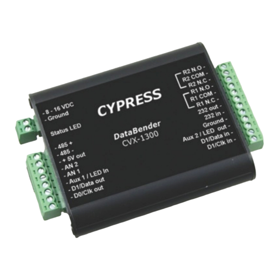
- Page 1 CVX-1300 Operations Manual DataBender™ Universal Format Converter CVX-1300_MAN_112011...
-
Page 2: Electrical And Mechanical Specifications
(1) This device may not cause harmful interference, and (2) this device must accept any interference received, including interference that may cause undesired operation. Cypress Computer Systems, Inc. ⌖ Lapeer, MI 48446 ⌖ www.cypresscomputer.com © 2011 Cypress Computer Systems Inc. - Page 3 1. First determine which converter (conversion process) is required for the application. This may be one of the standard Cypress converters or one of the new converters that are now part of the CVX-1300 library. All of the different conversion processes are described in detail in this manual.
-
Page 4: Electrical And Environmental Specifications
Supply Voltage Temperature/Voltage de-rating curve The CVX-1300 units should be operated with a filtered 12 Volt nominal DC supply. Any voltage between 8 and 16 volts can be utilized by following the temperature /voltage derating curve. Voltage should not exceed 16 VDC under normal operating conditions. - Page 5 Connections may or may not be utilized based on converter function. The Cypress CVX-1300 is based on the CVX-1200 series converter. For most legacy converter functions, the DIP switch settings will be set the same as with the Cypress CVX-1200.
- Page 6 CVX-1300 Serial data and RS485 The CVX-1300 can support both RS-232 and RS-485 signals for transmitting and receiving serial data. For most converters utilizing serial data, both interfaces are always active and may be used by making the appropriate connections to the converter. Either the RS-232 or RS-485 interface may be used, but a loss of data will occur if both interfaces have active data at the same time.
- Page 7 This Page left intentionally blank...
- Page 8 CVX-1300 Legacy Compatable formats Converter Input Output Settings(#) CVT2232 Wiegand 24 to 40 Serial 13 Digits with <CR> 1 , 2 , 3 CVT-2111 Wiegand 1 to 40 Serial Dec/Hex Digits 7, 8, 9 CVT-2110 Wiegand 1 to 48 SerialHex Digits...
- Page 9 CVX-1300 Legacy Compatable formats Converter Input Output Settings(#) CVT-5201 Wiegand 26 bit 10 digit Strobed/ABA CVT-2211 Wiegand ABA Serial ASCII 35,36 CVT-0126 Wiegand 26 bit Wiegand 26 bit fixed FC=215 104 CVT-9117A Serial Transcore Wiegand 26 CVT-3226 Wiegand 32 Bit Kastle...
- Page 10 DIP Switch Application Table DIP SWITCH SETTING DIP SWITCH SETTING DIP SWITCH SETTING DIP SWITCH SETTING DIP SWITCH SETTING DIP SWITCH SETTING DIP SWITCH SETTING DIP SWITCH SETTING INPUT INPUT OUTPUT OUTPUT 1 2 3 4 5 6 7 8 Interface Format Interface Format...
- Page 11 DIP Switch Application Table DIP SWITCH SETTING DIP SWITCH SETTING DIP SWITCH SETTING DIP SWITCH SETTING DIP SWITCH SETTING DIP SWITCH SETTING DIP SWITCH SETTING DIP SWITCH SETTING INPUT INPUT OUTPUT OUTPUT 1 2 3 4 5 6 7 8 Interface Format Interface Format...
- Page 12 DIP Switch Application Table DIP SWITCH SETTING DIP SWITCH SETTING DIP SWITCH SETTING DIP SWITCH SETTING DIP SWITCH SETTING DIP SWITCH SETTING DIP SWITCH SETTING DIP SWITCH SETTING INPUT INPUT OUTPUT OUTPUT 1 2 3 4 5 6 7 8 Interface Format Interface Format...
- Page 13 DIP Switch Application Table DIP SWITCH SETTING DIP SWITCH SETTING DIP SWITCH SETTING DIP SWITCH SETTING DIP SWITCH SETTING DIP SWITCH SETTING DIP SWITCH SETTING DIP SWITCH SETTING INPUT INPUT OUTPUT OUTPUT 1 2 3 4 5 6 7 8 Interface Format Interface Format...
- Page 14 Standard Wiring Diagrams - CVX-1300 Converter Wiring diagrams are referenced by function and number. The specific converter descriptions will refer to these diagrams. CVX-1300 Electrical Connections 1. Serial data and RS485 2. Standard power supply connections LISTING OF STANDARD WIRING DIAGRAMS 1.
- Page 15 Wiring Diagram #1 Wiegand to Serial Reader powered by external supply (8 to 16 VDC) Data0 D0/Clock In Card Data1 D1/Data In Reader LED Out Ground Ground RS232 Input RS232 Output Data Bender® Ground Power Connections +8 to +16 VDC In Supply to Serial Device...
- Page 16 Wiring Diagram #1 Wiegand to Serial Reader powered by converter +5 VDC Data0 D0/Clock In Card Data1 D1/Data In Reader LED Out Ground Ground RS232 Input +5VDC Out RS232 Output Data Bender® Ground Power Connections +8 to +16 VDC In Supply to Serial Device...
- Page 17 Wiring Diagram #2 Serial to Wiegand Data0 Data0 Out Data1 Data1 Out Access Ground Control Panel DB9-5 Ground RS232 Input +5VDC Out DB9-2 RS232 Output DB9-3 DB9-6 Data Bender® Connections to Serial Ground Power +8 to +16 VDC In Device Supply...
- Page 18 Wiring Diagram #3 Wiegand to Wiegand Reader powered by external supply (8 to 16 VDC) Data 0 D0 Output Data0 Data 1 D0 Input D1 Output Card Data1 Access D1 Input Reader Ground Control Panel Ground Ground Data Bender® Ground Power +8 to +16 VDC In Supply...
- Page 19 Wiring Diagram #4 Strobed to Serial Reader powered by external supply (8 to 16 VDC) Clock D0/Clock In Strobe D1/Data In LED Out Ground Ground RS232 Input Card RS232 Output Reader Data Bender® Ground Power Connections +8 to +16 VDC In Supply to Serial Device...
- Page 20 Wiring Diagram #4 Strobed to Serial Reader powered by converter +5 VDC Clock D0/Clock In Strobe D1/Data In LED Out Ground Ground RS232 Input +5VDC Out Card RS232 Output Reader Data Bender® Ground Power Connections +8 to +16 VDC In Supply to Serial Device...
- Page 21 Wiring Diagram #5 Serial to Strobed Clock Clock Out Data Data Out Access Ground Control Panel DB9-5 Ground RS232 Input DB9-2 +5VDC Out RS232 Output DB9-3 DB9-6 Data Bender® 5 Volts (If Used) Ground Power Connections +8 to +16 VDC In Supply to Serial Device...
- Page 22 Wiring Diagram #6 Strobed to Wiegand Reader powered by external supply (8 to 16 VDC) Data 0 Clock Data 1 D0/Clock In Strobe Access D1/Data In Ground Control LED Out Ground Panel Ground RS232 Input Card RS232 Output Reader Data Bender® Ground Power Connections...
- Page 23 Wiring Diagram #7 Wiegand to Strobed Reader powered by external supply (8 to 16 VDC) Clock Clock Out Data0 Data D0/Clock In Data Out Card Data1 Access D1/Data In Reader Ground Control Panel Ground Ground Data Bender® Ground Power +8 to +16 VDC In Supply Reader powered by 5 Volt Supply Clock...
- Page 24 Wiring Diagram #8 F2F to Wiegand Reader powered by external supply (8 to 16 VDC) Data 0 D0 Output Data 1 D1 Output Card Access F2F Input Reader Ground Control Panel Ground Ground Data Bender® Ground Power Supply +8 to +16 VDC In Reader powered by 5 Volt Supply Data 0 D0 Output...
- Page 25 Wiring Diagram #9 Serial to F2F F2F Output Access Ground Control Panel DB9-5 Ground RS232 Input DB9-2 +5VDC Out RS232 Output DB9-3 DB9-6 Data Bender® Connections Ground to Serial Power +8 to +16 VDC In Device Supply...
- Page 26 Wiring Diagram #10 IButton® to Wiegand 4.7 k Pullup Resistor Data 0 Data 1 IButton Center Contact Access Data In Ground Control Data In Ground Panel Ground +5VDC Out IButton® Reader Data Bender® Ground Power +8 to +16 VDC In Supply...
- Page 27 Wiring Diagram #11 Serial to Wiegand Special Application Data0 Data0 Out Data1 Data1 Out Access Ground Control Panel DB9-5 Ground RS232 Input DB9-2 +5VDC Out RS232 Output DB9-3 DB9-4 Data Bender® Connections Ground to Serial Power +8 to +16 VDC In Device Supply...
- Page 28 Wiring Diagram #12 Radionics to Wiegand Reader powered by external supply (8 to 16 VDC) Access Data 0 Control D0 Output Data 1 Panel D1 Output Ground Data Bender® +5VDC 485(-) 485(+) Data Out (SIG) Card Reader Ground Power +8 to +16 VDC In Supply Ground (-V) +VDC (+V)
Need help?
Do you have a question about the DataBender CVX-1300 and is the answer not in the manual?
Questions and answers