Table of Contents
Advertisement
Quick Links
Advertisement
Table of Contents

Related Manuals for Cypress CSC-5500


Summary of Contents for Cypress CSC-5500
- Page 1 CSC-5500 Multi Input Scaler Operation Manual Operation Manual...
- Page 2 SAFETY PRECAUTIONS Please read all instructions before attempting to unpack, install or operate this equipment and before connecting the power supply. Please keep the following in mind as you unpack and install this equipment: • Always follow basic safety precautions to reduce the risk of fi re, electrical shock and injury to persons.
-
Page 3: Table Of Contents
CONTENTS 1. Introduction ..........1 2. Applications ........... 1 3. Package Contents ........ 1 4. System Requirements ......1 5. Features ..........2 6. Operation Controls and Functions ..3 6.1 Front Panel .........3 6.2 Rear Panel .........4 6.3 Remote Control .........5 6.4 RS-232 Protocols ........6 6.5 RS-232 and Telnet Commands ..7 6.6 OSD Menu ........11... -
Page 4: Introduction
1. INTRODUCTION This Multi Input Scaler has Composite Video, Component Video, PC (VGA), and HDMI inputs and can switch and scale the signal to HDMI or VGA with audio outputs. It supports HDMI output resolutions up to 1080p/WUXGA and Analog Digital Conversion (ADC) and Digital Analog Conversion (DAC) allowing a wide range of AV signals to be displayed on a HDMI or VGA display. -
Page 5: Features
5. FEATURES • Supports switching and scaling of multiple AV inputs to HDMI or PC/ HD outputs • Supports EDID and HDCP • Supports 3D de-interlace, noise reduction and 3D comb fi lter • Supports frame rate conversion • Supports RS-232, IP(Telnet/Web GUI) and IR controls •... -
Page 6: Operation Controls And Functions
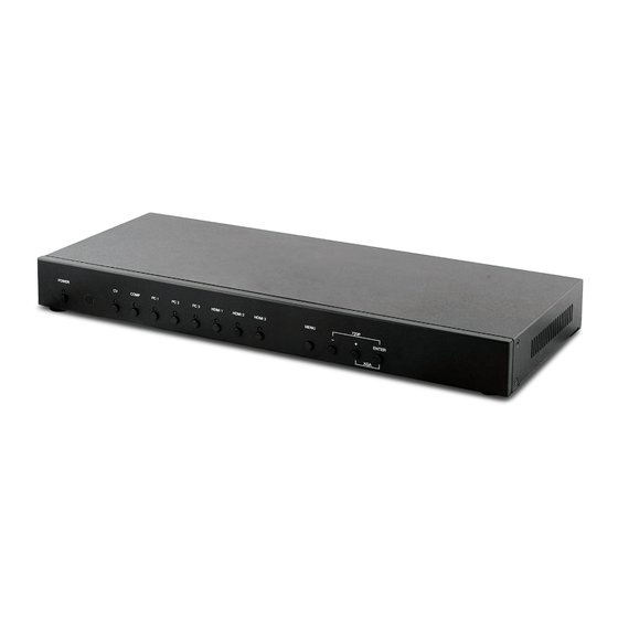
6. OPERATION CONTROLS AND FUNCTIONS 6.1 Front Panel 720P ENTER • POWER Button and LED: Press this button to switch the device on or to set it to standby mode. Once the device is connected to an active power supply and the Power Switch on the back panel is turned on, the LED will illuminate and the device will switch on automatically. -
Page 7: Rear Panel
6.2 Rear Panel IR IN SERVICE INPUT AUDIO RS232 COAX AUDIO CONTROL OUTPUT POWER DC 5V HDMI 1 HDMI 2 PC/HD Cr/Pr Cb/Pb IR IN: Connect the supplied IR extender to receive the IR signal from the included IR remote. Ensure that the remote is within the direct line-of-sight of the IR extender. -
Page 8: Remote Control
3) 3.5mm Mini-jacks: Connect to source's L/R output with 3.5mm mini-jack for audio signal conversion. Note: For HDMI signals you can select in the OSD Menu whether you require audio from the HDMI (AUTO) or from the analog audio inputs (EXT) 4) YCbCr/YPbPr + L/R: Connect to source equipment such as a DVD player for both video and audio signal conversion. -
Page 9: Rs-232 Protocols
6.4 RS-232 Protocols Multi-Input Scaler Remote Control Assignment Assignment ► ◄ Baud Rate: 19200bps Data bit: 8 bits Parity: None Flow Control: None Stop Bit: 1... -
Page 10: Rs-232 And Telnet Commands
6.5 RS-232 and Telnet Commands COMMAND DESCRIPTION S POWER 0/1 0=OFF 1=ON R POWER Reports the numeric equivalent for POWER setting (as above) S SOURCE 1~8 1=HDMI 1 5=VIDEO 2=HDMI 2 6=PC 1 3=HDMI 3 7=PC 2 4=YPbPr 8=PC 3 R SOURCE Reports the numerical equivalent for SOURCE setting (as above) - Page 11 COMMAND DESCRIPTION S INPUT HDCP 0/1 0=ON 1=OFF R INPUT HDCP Apple Computers Only. Reports the numerical equivalent for INPUT HDCP setting (as above) S SYNCSHIFT 0/1 0=ON 1=OFF R SYNCSHIFT Reports the numerical equivalent for SYNCSHIFT setting (as above) S CONTRAST 0~60 Sets the numerical equivalent for CONTRAST setting (0~60)
- Page 12 COMMAND DESCRIPTION S VOLUME 0~100 Sets the numerical equivalent for VOLUME setting (0~100) R VOLUME Reports the numerical equivalent for VOLUME setting S AUDIO DELAY 0~3 0=OFF 2=110ms 1=40ms 3=150ms R AUDIO DELAY Reports the numeric equivalent for the AUDIO DELAY setting (as above) S AUDIO MUTE 0/1 0=ON 1=MUTE...
- Page 13 COMMAND DESCRIPTION VOL - Lowers the volume level (VOLUME * IS SET) QUIT Exit. (Telnet Only) Note: Resolution settings 0~13 are RGB encoded. Resolution settings 14~21 are YUV encoded. RS-232 commands will be not executed unless followed with a carriage return (CR) command and for some systems a Line feed (LF) command.
-
Page 14: Osd Menu
6.6 OSD Menu MAIN MENU SUB MENU 3RD MENU 4TH MENU DISPLAY OUTPUT 640×480 60 800×600 60 1024×768 60 1280×768 60 1360×768 60 1280×720 60 1280×800 60 1280×1024 60 1440×900 60 1400×1050 60 1680×1050 60 1600×1200 60 1920×1080 60 1920×1200 60 1280×720P 60* 1920×1080I 60 1920×1080P 60... - Page 15 MAIN MENU SUB MENU 3RD MENU 4TH MENU DISPLAY SIZE OVER SCAN FULL* FOLLOW INPUT PAN SCAN LETTER BOX UNDER 2 UNDER 1 MODE INFO INFO* INPUT HDCP (HDMI mode only) AUTO SETUP (PC mode only) H_POSITION V_POSITION PHASE CLOCK XGA* WXGA/XGA WXGA...
- Page 16 MAIN MENU SUB MENU 3RD MENU 4TH MENU COLOR CONTRAST 0~60 (30) BRIGHTNESS 0~60 (30) COLOR R 0~1023 (512) G 0~1023 (512) B 0~1023 (512) R OFFSET 0~1023 (512) G OFFSET 0~1023 (512) B OFFSET 0~1023 (512) 0~60 (30) SATURATION 0~60 (30) SHARPNESS 0~30 (0)
- Page 17 MAIN MENU SUB MENU 3RD MENU 4TH MENU SETUP FACTORY RESET* OFF* KEY LOCK OFF* POWER SAVE DHCP* IP MODE STATIC SET STATIC IP IP ADDRESS 0.0.0.0.~ 255.255.255.255* SUBNET MASK 0.0.0.0.~ 255.255.255.255* DEF.GETWAY 0.0.0.0.~ 255.255.255.255* FREERUN BLACK BLUE* COLOR INFORMATION INPUT OUTPUT REVISION IP ADDRESS...
-
Page 18: Telnet Control
The FACTORY RESET option in the OSD menu will only reset part of settings. For a complete reset of the system, please use the reset button on the remote control. 192.168.0.1 (Default setting). 255.255.255.0 (Default setting). 192.168.0.254 (Default setting). Items in BOLD with an asterisk (*) are the Factory default settings. Items in brackets are the default values for those settings. - Page 19 Once in the command line interface (CLI) type 'telnet' along with the IP address of the unit you wish to control (see below for reference). This will bring us into the device which we wish to control. Note: The IP address can be obtained from the OSD menu under Information.
-
Page 20: Web Gui Control
6.8 Web GUI Control On a PC/Laptop that is connected to same active network as the Scaler, open a web browser and type device's IP address on the web address entry bar. The browser will bring up the control page of the Scaler (see below for reference). -
Page 21: Input Resolution Support
6.9 Input Resolution Support Input Component HDMI Resolution NTSC/PAL 480i/576i 480p/576p 720p@50/60 Hz 1080i@50/60 Hz 1080p@50/60 Hz VGA@60/72/75 Hz SVGA@56/60/72/75 Hz XGA@60/70/75 Hz SXGA@60/75 Hz ... -
Page 22: Output Resolution Support
6.10 Output Resolution Support Output PC/HD HDMI Resolution 480p/576p 720p@50/60 Hz 1080i@50/60 Hz 1080p@50/60 Hz VGA@60 Hz SVGA@60 Hz XGA@60 Hz SXGA@60 Hz UXGA@60 Hz 1280×768@60 Hz ... -
Page 23: Connection Diagram
7. CONNECTION DIAGRAM PCs/Laptops VGA and Analog Stereo Inputs AV Receiver Smartphone/ Tablet device DVD Player Coaxial Analog Digital Stereo Audio Audio Component Output Output and Analog Modem/ Stereo Inputs Router CAT Cable RS-232 Equipped PC or Control System IR IN SERVICE INPUT Power... -
Page 24: Specifi Cations
8. SPECIFICATIONS Input Ports 3×HDMI, 3×VGA, 1×Component Video, 1×Composite Video, 2×RCA (Analog Stereo L/R), 6×3.5mm Mini-jack, 1×Extender, 1×USB (Service), 1×RJ45 (Control), 1×RS-232 (Control) Output Ports 2×HDMI, 1×VGA/Component Video, 1×Coaxial, 1×3.5mm Mini-jack Input Resolution Support Up to UXGA & 1080p Output Resolution Support Up to WUXGA (RB) &... -
Page 25: Acronyms
9. ACRONYMS ACRONYM COMPLETE TERM COMP Component Video Composite Video Red Green Blue Video Graphics Array UXGA Ultra Extended Graphics Array WUXGA Widescreen Ultra Extended Graphics Array...
Need help?
Do you have a question about the CSC-5500 and is the answer not in the manual?
Questions and answers