IBM 4820 Planning, Installation And Service Manual
4820 surepoint solution
Hide thumbs
Also See for 4820:
- System reference manual (124 pages) ,
- Planning, installation and service manual (112 pages)

Related Manuals for IBM 4820


Summary of Contents for IBM 4820
- Page 1 4820 SurePoint Solution Planning, Installation and Service Guide Update November 2005 GA27-4231-07...
- Page 3 4820 SurePoint Solution Planning, Installation and Service Guide Update November 2005 GA27-4231-07...
- Page 4 Research Triangle Park, NC 27709-9990 USA When you send information to IBM, you grant IBM a nonexclusive right to use or distribute whatever information you supply in any way it believes appropriate without incurring any obligation to you. © Copyright International Business Machines Corporation 1999, 2005. All rights reserved.
-
Page 5: Table Of Contents
Appendix A. Field-replaceable units ....81 Assembly 1: 4820 ......82 Assembly 2: 4820 mounting hardware . - Page 6 Appendix D. Safety information ....97 Index ......103 4820 Planning, Installation and Service Guide...
-
Page 7: Figures
2. Pedestal types ....... . 4 3. Front view of 4820 ....... 6 4. - Page 8 ..... . 89 62. Free-standing pedestal mounting template ..... 90 4820 Planning, Installation and Service Guide...
- Page 9 4. Environmental requirements ......8 5. Power usage for 4820 SurePoint Solution ..... . 9 6.
- Page 10 Update November 2005 viii 4820 Planning, Installation and Service Guide...
-
Page 11: About This Guide
4820 SurePoint Solution. v Chapter 2, “Installing the IBM 4820,” on page 11 provides the installation steps for the display and the features. v Chapter 3, “Maintaining the IBM 4820,” on page 67 describes common maintenance procedures for all models of the 4820. -
Page 12: Tell Us What You Think
Update November 2005 Driver and service diskette information Under SurePOS Peripherals, click IBM SurePoint Solution to go to the IBM 4820 SurePoint System Support page, where you can download the following software: v 4694/4695/ISA Service/Diagnostic Diskette, Version 5.33 or later v 4820 Touch Drivers, including: –... -
Page 13: Accessibility
To assist users with color-vision deficiencies, the power LED blinks as well as changes color when in low-power mode. v Displays are driven at 60 Hz to eliminate problems caused by screen flicker. © Copyright IBM Corp. 1999, 2005... - Page 14 Update November 2005 4820 Planning, Installation and Service Guide...
-
Page 15: Summary Of Changes
This edition adds information about the features of Models 4WT and 4GT of the 4820 SurePoint Solution. July 2002 This edition adds information about Models 10D and 1FR of the 4820 SurePoint Solution. January 2002 This edition adds information about the integrated touch pedestal available for the 4694 Point of Sale terminal. - Page 16 Update November 2005 v Digital Visual Interface (DVI) 4820 Planning, Installation and Service Guide...
-
Page 17: Chapter 1. Introducing The Ibm 4820 Surepoint Solution
10 in. Iron gray None Supports all Notes: 1. Options are selected by feature code. 2. Touch drivers must be obtained from the IBM Web site (www.ibm.com/solutions/retail/store/). Drivers from other sources are not supported. © Copyright IBM Corp. 1999, 2005... -
Page 18: Surepoint Solution With Features And Available Pedestals
Update November 2005 Figure 1. 4820 SurePoint Solution with features and available pedestals 4820 Planning, Installation and Service Guide... -
Page 19: Hardware Options
– Short: 255 mm (10 in.) – Tall: 380 mm (15 in.) v Distributed pedestal – Short: 240 mm(9.38 in.) – Tall: 352 mm (13.80 in.) v Free-standing pedestal v VESA bracket Chapter 1. Introducing the IBM 4820 SurePoint Solution... -
Page 20: Pedestal Options
Update November 2005 Pedestal options The pedestal options for the 4820 SurePoint Solution are integrated, free-standing, or distributed pedestal. See Figure 2. Figure 2. Pedestal types 4820 Planning, Installation and Service Guide... -
Page 21: Supported Operating Systems
| | | | | | 4820-46D | | | | | | 4820-48D Version 2, Release 3 | | | | | | 4820-10D | | | | | | 4820-1FR Chapter 1. Introducing the IBM 4820 SurePoint Solution... -
Page 22: Views Of The 4820 Surepoint Solution
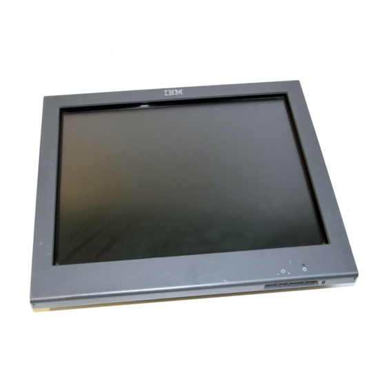
This section shows examples of the various models of the 4820 SurePoint Solution. 12.1-inch and 15.0-inch models Figure 3 is a front view of the 12.1-inch and 15.0 inch models of the 4820 SurePoint Solution. Note the location of the control buttons. -
Page 23: Rear View Of 4820
Update November 2005 Figure 4 is a rear view of the 12.1-inch and 15.0-inch models of the 4820 SurePoint Solution. This view shows the keypad, the locating tabs for the MSR, and the audio kit, connector, and connector cover. Note the location of the manager’s keylock. -
Page 24: System Software, Touch Drivers, And Diagnostics
Figure 5 shows the front and rear views of the 10-inch models. Figure 5. Views of 10-inch models System software, touch drivers, and diagnostics You can obtain the appropriate software for your 4820 SurePoint Solution from the IBM Retail Store Solutions Web site:www.ibm.com/solutions/retail/store/ (from the store page, click Support). -
Page 25: Power Usage
Standards Publication number 250-1991 Enclosures for Electrical Equipment v IP 52 rating per IEC 529 Calling for service When you call IBM for warranty information or service, be sure to have the following information available: v Machine type/model v Serial number Locate this information either on the lower-right edge at the rear, or on the side of the machine. - Page 26 Update November 2005 4820 Planning, Installation and Service Guide...
-
Page 27: Chapter 2. Installing The Ibm 4820
6. Connect the cables to your system unit. 7. Power on the system and the 4820 display. See to “Powering on” on page 52 8. Perform an auto adjust to obtain the optimal image. See “Adjusting the image”... -
Page 28: Identifying The Pedestal Type
4820 SurePoint Solution. Figure 6. Pedestal types Identifying the 4820 cables This section identifies the EIA-232 cables for the various models of the 4820 SurePoint Solution. Models with IR touch: 2xx and 5xx Touch with MSR/keypad Figure 7. -
Page 29: Infrared Touch With Msr
Touch with MSR Figure 8. Infrared touch with MSR | | | EIA-232 touch (host) EIA-232 MSR (host) EIA-232 touch/MSR (4820) Touch only Figure 9. Touch only | | | EIA-232 touch (host) EIA-232 touch (4820) Chapter 2. Installing the IBM 4820... -
Page 30: Infrared Touch (Powered)
Installing the IBM 4820 Update November 2005 Touch (powered) Figure 10. Infrared touch (powered) | | | EIA-232 touch (host) 12vdc power(host) EIA-232 touch/power (4820) 4820 Planning, Installation and Service Guide... -
Page 31: Connector Cable For Capacitive And Resistive Touch Eia-232 Models
EIA-232 MSR (host) Keypad/keyboard (host) PS/2 keyboard (for diagnostics) EIA-232 touch/MSR/keypad (4820) Touch with MSR Figure 12. 4820-4FT model with MSR attached | | | EIA-232 touch (host) EIA-232 MSR (host) EIA-232 touch/MSR (4820) Chapter 2. Installing the IBM 4820... -
Page 32: Microphone Cable For Amplified Speaker Kit
Installing the IBM 4820 Update November 2005 Microphone Figure 13. Microphone cable for amplified speaker kit | | | Microphone cable (4820 amplified speaker kit) USB (host) Microphone (host) 4820 Planning, Installation and Service Guide... -
Page 33: Identifying The 4820 I/O Ports
Installing the IBM 4820 Update November 2005 Identifying the 4820 I/O ports This section identifies the input/output ports of the various 4820 models. See Figure 12 on page 15. Note: This section does not show all possible configurations. Models 2xx, 5xx Figure 14. -
Page 34: Models 46T, 46R I/O Ports
12 V dc power USB 1.1 (two units for external connections) Video connector USB 2.0 PS/2 keyboard Enable/disable audible port for beeper (Models 42T diagnostics and 4FT) EIA-232 connector RS-485 (EIA 485) port connector port 4820 Planning, Installation and Service Guide... -
Page 35: Connector Icons
Installing the IBM 4820 Update November 2005 Identifying the icons Icons located near the 4820 SurePoint Solution ports also identify the connection type. Table 7 lists these icons. Table 7. Connector icons Power Video USB/RS-485/EIA-232 Touch/MSR USB out Enable audible beeper (Models 4FT, 42T only) Disable audible beeper (Models 4FT, 42T only) ®... -
Page 36: Installing The Pedestal
This section describes how to install the distributed, integrated, integrated touch and free-standing pedestal. Cable routing steps are included. Distributed pedestal Follow these instructions for installing the 4820 SurePoint Solution to the distributed pedestal: Attaching the distributed pedestal to the counter The distributed pedestal is available in short (238.2 mm/9.38 inches) and tall (350.6... -
Page 37: Video Cable Routing Direction
Routing the cables for the distributed pedestal 1. Remove the trough cover from the distributed pedestal. 2. Route the video cable down through the distributed pedestal (as shown Figure 20) and leave it unconnected. Figure 20. Video cable routing direction Chapter 2. Installing the IBM 4820... -
Page 38: Using The Velcro Strip
Distributed pedestal instructions Update November 2005 3. Using the velcro strip that is connected to the power cable, fasten the power and video cables together (see Figure 21). Figure 21. Using the velcro strip 4820 Planning, Installation and Service Guide... -
Page 39: Routing The Video And Power Cables
6. Route the video cable back down through the distributed pedestal. 7. Attach the video cable to the appropriate port in the system unit. Note: Do not attach the video and power cables to the 4820 display. 8. Install your optional hardware. (See “Installing options” on page 43.) -
Page 40: Distributed Pedestal Parts (Shown With Short Pedestal)
1. Ensure that the pedestal is secure. 2. Mount the 4820 onto the pedestal: a. Place the 4820 display on the distributed pedestal. Make sure that the metal tabs on the mounting bracket slide into the appropriate slots on the back of the 4820 display. -
Page 41: Distributed Pedestal Covers
5. Plug the power brick into an outlet. 6. Power on the system unit. See “Power usage” on page 9. 7. Auto adjust your screen for maximum viewing. (See “Adjusting the image” on page 53.) Chapter 2. Installing the IBM 4820... -
Page 42: Pedestal (Free-Standing) Parts
4. See “Tailoring your installation” on page 11 and continue with your installation. Mounting the 4820 to the free-standing pedestal Review the parts diagram in Figure 25, and then follow the steps to attach the 4820 SurePoint Solution to the free-standing pedestal:... -
Page 43: Placement Of Cable Covers
Free-standing pedestal instructions Update November 2005 2. Place the 4820 display on the free-standing pedestal. Make sure that the metal tabs on the mounting bracket slide into the appropriate slots on the back of the 4820 display. 3. Secure the 4820 to the mounting bracket by using four screws. -
Page 44: Routing The Cables
Routing the cables for the integrated pedestal 1. Attach the video cable to the appropriate port on the system unit. 2. Route the video cable and the power cable for the 4820 display through the opening of the system unit. -
Page 45: Integrated Pedestal Parts
Integrated base plate Thumb screws Figure 28. Integrated pedestal parts Follow these steps to attach the 4820 to the integrated pedestal: 1. Ensure that you have routed the cables. 2. Secure the pedestal to the system unit: a. Align the holes of the integrated base plate with the holes in the unit. -
Page 46: Routing The Power Cable
Integrated pedestal instructions Update November 2005 4. Route the power cable and secure it to the mounting bracket with a cable tie as shown in Figure 29. Figure 29. Routing the power cable 4820 Planning, Installation and Service Guide... -
Page 47: Integrated Pedestal Covers
6. Plug the power cord into an outlet and power on the system unit. See “Power usage” on page 9. 7. Auto-adjust your screen for optimum viewing (see “Adjusting the image” on page 53). Chapter 2. Installing the IBM 4820... -
Page 48: Routing The Cables
1. Attach the video cables and touch cable to the appropriate port on the system unit. 2. Route the video cables and touch cable for the 4820 display through the opening of the system unit. 3. Separately route these cables up through the base of the integrated pedestal as shown in Figure 31. -
Page 49: Integrated Pedestal Parts
Integrated pedestal instructions for 5xx models Update November 2005 Mounting the 4820 SurePoint Solution to the integrated pedestal Figure 32 shows the parts of the integrated pedestal. Figure 32. Integrated pedestal parts Chapter 2. Installing the IBM 4820... -
Page 50: Routing The Power Cable
Tighten the thumb screws securely. Note: See “Integrated touch pedestal” on page 36. 3. Mount the 4820 onto the pedestal. a. Route and attach the power and video cables to the 4820 display (as shown in Figure 33). Figure 33. Routing the power cable... -
Page 51: Integrated Pedestal Covers
Place the display on the pedestal mounting bracket (see Figure 34). Figure 34. Integrated pedestal covers c. Secure the 4820 to the pedestal by using four screws. Note: Ensure that you have attached the cables to the appropriate ports in the back of the system unit. -
Page 52: Inserting The Stiffening Plate
Note: Figure 35 illustrates the right-oriented placement of the arm. Rotate the plate over for a left-oriented placement. 3. Fasten the counter-sunk washers and screws to the stiffening plate. 4. Route the cables as described for your 4820 model. 4820 Planning, Installation and Service Guide... -
Page 53: Securing The Arm Assembly To The 4694
Figure 36. Securing the arm assembly to the 4694 Note: The left or right placement of the arm assembly depends upon your configuration. 6. Attach the 4820 to the pedestal. 7. Install the options. (See “Installing options” on page 43.) Chapter 2. Installing the IBM 4820... -
Page 54: Attaching The Filler Panel Covers
Integrated touch pedestal instructions Update November 2005 8. Place the filler panel covers on the arm assembly as shown in Figure 37. Figure 37. Attaching the filler panel covers 4820 Planning, Installation and Service Guide... -
Page 55: Securing The Arm Assembly To Surepos 720, 740, 780
From the inside of the top cover, push the rubber plugs out of the plastic. c. Reinstall the top cover and the integration tray. 2. Route the cables as described for your 4820 model. 3. Place the arm assembly on the slant tray as shown in Figure 38. Insert and tighten the four thumb screws as shown. -
Page 56: Attaching The Filler Panel Covers
5. Place the filler panel covers on the arm assembly as shown in Figure 39. Figure 39. Attaching the filler panel covers 6. See “Tailoring your installation” on page 11 and continue with your installation. 4820 Planning, Installation and Service Guide... -
Page 57: Securing The Arm Assembly To The Surepos 720, 740, 780
Reinstall the top cover. 2. Install the arm assembly in the box filler panel. 3. Route the cables as described for your 4820 model. 4. Place the arm assembly on the system unit as shown in Figure 40. Insert and tighten the four thumb screws as shown. -
Page 58: Installing The Vesa Bracket
1. Connect the cables (keypad/MSR/touch, video, power) to the appropriate ports on the back of the 4820. 2. Install the options on your 4820. See “Installing options” on page 43 3. Attach the VESA bracket to the 4820 by using four screws. -
Page 59: Installing Options
Note: Install the audio kit when you install the covers. Installing the manager’s keylock The empty lock cylinder (see Figure 4 on page 7) of the 4820 SurePoint Solution contains a slot that matches the lock’s insert. Your objective is to adjust this slot so that the lock will fit snugly into the cylinder. -
Page 60: Lock Insert And Brass Key
9. Hold the lock insert in place with your finger and remove the brass key. 10. Test the lock to ensure that it operates correctly with the keys. 11. Continue with the install as described in “Attaching the MSR/keypad” on page 4820 Planning, Installation and Service Guide... -
Page 61: Surepoint Solution With Attached Keypad/Msr
MSR/keypad downward ( 2 ) until it snaps into place. v All other models: Align the MSR/keypad with the edge ( 1 ) of the 4820 so that the top edge of the 4820 aligns with the top of the keypad. Slide the keypad unit downward ( 2 ) until it snaps into place. -
Page 62: Rear View Of Attached Keypad
Installing options Update November 2005 Figure 45. Rear view of attached keypad 4. Install the replacement connector cover that shipped with the keypad. 5. Continue with the installation of your next option. 4820 Planning, Installation and Service Guide... -
Page 63: Surepoint Solution With Msr
MSR downward ( 2 ) until it snaps into place. v All other models: Align the MSR with the edge ( 1 ) of the 4820 so that the top edge of the 4820 aligns with the top of the keypad. Slide the keypad unit downward ( 2 ) until it snaps into place. -
Page 64: Tabs For Attaching The Pointing Device
Figure 48 on page 49. Follow these steps to attach the pointing device to the 4820 SurePoint Solution: 1. Before you begin, locate the tabs for the pointing device on the rear of the 4820 (see Figure 47). -
Page 65: Surepoint Solution With Optional Pointing Device
Attaching the audio kit Notes: 1. The optional audio kit is a replacement for the mounting cover of the 4820 SurePoint Solution. If this is an initial installation of the 4820 SurePoint Solution, install the audio kit when you install the covers. -
Page 66: Optional Button Cover
1. Because the button cover is somewhat difficult to remove, auto-adjust the display (see “Adjusting the image” on page 53) before installing the cover. 2. Align the button cover with the buttons located on the bottom of the 4820 ( A in Figure 49). -
Page 67: Path Of Pointing Device Cable
Update November 2005 Routing the pointing device cable (integrated and distributed) 1. Before attaching the 4820 display to the mounting bracket, route the pointing device cable through the middle opening of the mounting bracket into the trough, and down through the pedestal (see Figure 50). -
Page 68: Powering On
Point of Sale terminal and do not require a power adapter (see “Power usage” on page 9). 1. If a power adapter is required, connect it to the 4820 and an electrical outlet. The 4820 power light-emitting diode (LED) glows green. -
Page 69: Adjusting The Image
Figure 51. On-screen display menu Auto Adjust Automatically adjusts the video settings. Use this option when you install the display and at any time the video mode is changed, or the 4820 is moved to another host system. Manual Adjust Allows you to modify the clock, phase, and image position. - Page 70 Adjust frequently because it automatically fine tunes your settings based on your PC’s video signal. DOS users: To run the 4820 Video Quality Test Pattern program for DOS users, follow these steps: 1. Download the 4820Patt.exe program from the support Web site: www.ibm.com/solutions/retail/store, then click Support, and create a diskette.
-
Page 71: Pattern Display Using The 4820 Video Quality Test Pattern Program
Adjusting the image Update November 2005 Windows users: To run the 4820 Video Quality Test Pattern program for Windows users, follow these steps: 1. Download the 4820Patt.exe program from the support Web site (www.ibm.com/solutions/retail/store, then click Support) and build a diskette. -
Page 72: On-Screen Display Menu (Models 2Xx And 5Xx)
Allows adjustment of the horizontal location of the image. V-Position Allows adjustment of the vertical location of the image. Clock Allows adjustment of display timings (rarely required and not recommended) Phase Allows adjustment of display timings (rarely required and not recommended) 4820 Planning, Installation and Service Guide... - Page 73 Saves the current settings and exits the OSD Note: The only functions usually needed are Autoadjust, Brightness, and Information. It is not necessary to modify the other settings in the course of normal operation. Chapter 2. Installing the IBM 4820...
-
Page 74: Configuring And Calibrating The Touch Screen
This section describes how to configure and calibrate the touch screen. For information on your model type, refer to Table 1 on page 1. Models 42T, 46T, 48T, 4WT, 4GT, 4FT, 46R This section applies only the 4820 models with the capacitive and resistive touch technology. When to adjust... -
Page 75: Calibrate Tab
Configuring and calibrating the touch screen Update November 2005 If you click Calibrate, you can select from three tabs: Calibration, Click Settings, and Hardware. The Calibrate tab (Figure 55) enables you to calibrate the display. Figure 55. Calibrate tab Chapter 2. Installing the IBM 4820... -
Page 76: Hardware Tab
The Click Settings tab specifies the touch click settings. The Hardware tab (Figure 56) is used to restore the hardware default settings. Figure 56. Hardware tab If you change the screen resolution, a Calibrate reminder dialog (Figure 57) is displayed. Figure 57. Calibrate reminder dialog 4820 Planning, Installation and Service Guide... - Page 77 Update November 2005 IBM POS Device Diagnostics tool The IBM POS Device Diagnostics is a diagnostics tool that allows you to test the 4820 when it is attached to the SurePOS 700 Series system unit. This tool installs ® ®...
-
Page 78: Customizing The Touch Response Mode
The system moves the cursor to the touch point, generates a button down, waits for a system-defined time delay, and generates a button up. The system does not generate a mouse event on finger lift-off. The system does not support drag in this mode. 4820 Planning, Installation and Service Guide... -
Page 79: Summary Of Touch Response Modes
The ranges of these settings are listed in Table 9. Table 9. Touch sound settings | | | | Setting Range Increment Default | | | | Frequency (Hz) 200 to 5000 1500 | | | Duration 50 to 600 (milliseconds) Chapter 2. Installing the IBM 4820... - Page 80 50/60 Hz touch systems. This option is intended only for use in ungrounded systems. The default setting of Filtering is disabled. If erratic touch problems occur, you should enable Filtering. 4820 Planning, Installation and Service Guide...
- Page 81 This section applies to the infrared-touch technology available in Models 2xx and 5xx. IBM Advanced Touch Screen Configurator The IBM Advanced Touch Screen Configurator program is available from the support web site and provides additional features for your touch software. The readme.htm file provides complete installation and user instructions. The program...
- Page 82 Configuring and calibrating the touch screen Update November 2005 4820 Planning, Installation and Service Guide...
-
Page 83: Chapter 3. Maintaining The Ibm 4820
Update November 2005 Chapter 3. Maintaining the IBM 4820 Note: Information in this chapter is for all models of the 4820 SurePoint Solution. Maximizing your comfort Before you begin using your display, follow these tips to ensure that you are comfortable: v Keep your head in a comfortable viewing position. - Page 84 Update November 2005 4820 Planning, Installation and Service Guide...
-
Page 85: Chapter 4. Troubleshooting Common Problems
Testing the power supply ....79 This section describes several common problems and explains what to do. Note: Some 4820 image problems can be caused by problems in the system unit to which the display is attached. -
Page 86: Correct Connections For Servicing Eia-232 Models
EIA-232 touch connects to COM 1 v EIA-232 MSR connects to COM 2 v PS/2 pigtail is attached to a keyboard The service software can correctly evaluate your 4820 display only with these connections. Touch screen controller information The touch screen controller information window provides information about the type, firmware version, and status of your touch screen. -
Page 87: Touch Screen Status Messages
Update November 2005 Controller type The Controller Type field displays the model name of your touch screen controller. Firmware version The Firmware Version field displays the revision number of the firmware in your TouchWare software controller. Touch screen status The Touch screen Status field provides valuable information about whether the touch screen hardware is operating properly. -
Page 88: Troubleshooting The 4820 Infrared Touch Screen Using The Elo Touch Properties Page
Troubleshooting the 4820 Infrared touch screen using the ELO Touch Properties Page The 4820 Infrared touch models use the ELO driver, which is Windows-based and is used for both USB and EIA-232 models. To access the ELO properties, use the ELO Touch properties page: 1. -
Page 89: Troubleshooting Display Beep
Use this tab to ensure that the latest driver that is available on the IBM web site is installed. (www.ibm.com/solutions/retail/store) Troubleshooting display beep If the IBM Advanced Touchscreen Configurator has been installed, but the display is not beeping as configured, reload the beep configuration. Go to: Start ==>... -
Page 90: All Models
Resolution The power indicator on the display is off Models 42x and 4Fx only Ensure that the 4820 is powered on by pressing the power button on the display. Models 42x, 4Fx, 46x, 10D, 1FR EIA-232 only: Models 2xx, 5xx 1. - Page 91 No Video/low power mode message Communication is not yet established between the host unit and the 4820. 1. Verify that the system unit is powered on. 2. Check the video cabling between the 4820 display and the system unit. Chapter 4. Troubleshooting common problems...
- Page 92 Press (+) and (-) at the same time to save the setting. 4. Run the 4820 Video Quality Test Pattern program (excluding models 48x, 10D, 1FR, 2xx, and 5xx). Models 46x, 42x, and 4Fx, use the service diskette and run the display test for your host system.
- Page 93 2. Run the pointing device test using the service diskette, if available for your model. 3. Replace the pointing device. 4. For models 48D, 48T, see the IBM POS Device Diagnostics, which came with the POSS for Windows installation. Capacitive and Resistive Touch Problems...
-
Page 94: Supported Video Modes
60, 70, 75 LED states The 4820 SurePoint Solution has a dual-color LED: green or amber. The monitor’s power management state determines the lighting of the LED. Green indicates full power usage, and amber indicates low power mode or no detected video signal. -
Page 95: Power Adapter Pinouts
Power adapter If your 4820 SurePoint Solution uses a power adapter (also known as a power brick), test the voltages of the adapter’s power cable. v Models 10D and 1FR use a +12V adapter (part number 66P0405). -
Page 96: Powered Usb Connector And Pin Numbers
POW terminal (see “Power usage” on page 9). The powered USB cable provides approximately 12V dc. If your 4820 SurePoint Solution is powered by a USB cable, test the pin voltages to verify that they are correct. Table 13 lists the pinouts for the USB connector and the acceptable voltages for the power provided by the cable. -
Page 97: Appendix A. Field-Replaceable Units
Appendix A. Field-replaceable units Assembly 1: 4820 ......82 Assembly 2: 4820 mounting hardware ....86... -
Page 98: Assembly 1: 4820
FRU parts list Update November 2005 Assembly 1: 4820 4820 Planning, Installation and Service Guide... - Page 99 1 4820, model 4GT (with I/O support), iron gray –1 14J0842 1 4820, model 2WN (USB), pearl white –1 14J0848 1 4820, model 2WN (USB with I/O support), pearl white | | | | –1 14J0854 1 4820, model 2WN (EIA-232), pearl white | | | | –1...
- Page 100 Power cords for models 4xx: –11 76H3516 1 v Power cord, US –11 76H3514 1 v Power cord, Argentina/Australia/New Zealand –11 76H3518 1 v Power cord, Austria/Belgium/France/Germany –11 76H3520 1 v Power cord, Denmark 4820 Planning, Installation and Service Guide...
- Page 101 Assembly 1: (continued) Update November 2005 Asm– Part Index Number Units Description –11 76H3522 1 v Power cord, South Africa –11 76H3526 1 v Power cord, Japan –11 76H3528 1 v Power cord, Switzerland –11 76H3530 1 v Power cord, Chile/Ethiopia –11 76H3535 1 v Power cord, Korea...
-
Page 102: Assembly 2: 4820 Mounting Hardware
FRU parts list Update November 2005 Assembly 2: 4820 mounting hardware 4820 Planning, Installation and Service Guide... - Page 103 Assembly 2: (continued) Update November 2005 Asm– Part Index Number Units Description 2–1 66P0402 1 Hinge cover, pearl white –1 66P0403 1 Hinge cover, iron gray | | | | –1 29R0945 1 Hinge cover, 15″ integrated stand pedestal, pearl white | | | | –1 29R0947...
- Page 104 Assembly 2: (continued) Update November 2005 4820 Planning, Installation and Service Guide...
-
Page 105: Appendix B. Mounting Surface Templates
Use the template in Figure 61 as a guide for mounting the distributed pedestal assembly. 8 mm (0.31 in.) diameter 62 mm 22 mm (0.87 in.) (2.44 in.) diameter 35 mm (1.37 in.) 20 mm (0.80 in.) Figure 61. Distributed pedestal mounting template © Copyright IBM Corp. 1999, 2005... -
Page 106: Free-Standing Pedestal Mounting Template
Use the template in Figure 62 as a guide for mounting the free-standing pedestal. Front Diameter=7.2 mm (0.28 in.) 19.6 mm (0.77 in.) Diameter=12 mm (0.47 in.) 75.3 mm (2.96 in.) Diameter=7.2 mm (0.28 in.) Back Figure 62. Free-standing pedestal mounting template 4820 Planning, Installation and Service Guide... -
Page 107: Appendix C. Notices
References in this publication to IBM products, programs, and services do not imply that IBM intends to make these available in all countries in which IBM operates. Any reference to an IBM product, program, or service is not that only IBM’s product, program, or service may be used. -
Page 108: Electronic Emission Notices
Properly shielded and grounded cables and connectors must be used in order to meet FCC emission limits. IBM is not responsible for any radio or television interference caused by using other than recommended cables and connectors or by unauthorized changes or modifications to this equipment. -
Page 109: Japanese Power Line Harmonics Compliance Statement
In solch einem Fall ist der Abstand bzw. die Abschirmung zu der industriellen Störquelle zu vergröβern.″ Anmerkung: Um die Einhaltung des EMVG sicherzustellen, sind die Geräte, wie in den IBM Handbüchern angegeben, zu installieren und zu betreiben. Australia / New Zealand Attention: This is a Class A product. -
Page 110: Korean Communications Statement
Logic cards removed from a product should be placed in ESD protective containers. No other object should be allowed inside the ESD container with the logic card. Attach tags or reports that must accompany the card to the outside of the container. 4820 Planning, Installation and Service Guide... -
Page 111: End Of Life Disposal
In the United States, IBM has established a return process for reuse, recycling, or proper disposal of used IBM sealed lead acid, nickel cadmium, nickel metal hydride, and other battery packs from IBM equipment. For information on proper disposal of these batteries, contact IBM at 1-800-426-4333. -
Page 112: Mercury-Added Statement
Trademarks IBM, the IBM logo, PS/2, SureMark and surePoint are trademarks of IBM Corporation in the United States or other countries or both. Microsoft, Windows, Windows NT, and the Windows 95 logo are trademarks or registered trademarks of Microsoft Corporation. -
Page 113: Appendix D. Safety Information
Update November 2005 Appendix D. Safety information Danger: Before you begin to install this product, read the safety information in IBM Safety Information — Read This First, GA27-4004. This booklet describes safe procedures for cabling and plugging in electrical equipment. - Page 114 Gevaar Voordat u begint met het installeren van dit produkt, dient u eerst de veiligheidsrichtlijnen te lezen die zijn vermeld in de publikatie IBM Safety Information — Read This First, GA27-4004. In dit boekje vindt u veilige procedures voor het aansluiten van elektrische appratuur.
- Page 115 Update November 2005 Vigyázat Mielôtt megkezdi a berendezés üzembe helyezését, olvassa el a IBM Safety Information — Read This First, GA27-4004 könyvecskében leírt biztonsági információkat. Ez a könyv leírja, milyen biztonsági intézkedéseket kell megtenni az elektromos berendezés huzalozásakor illetve csatlakoztatásakor.
- Page 116 Varning—livsfara Innan du börjar installera den här produkten bör du läsa säkerhetsinformationen i dikumentet Säkerhetsföreskrifter—Läs detta först, GA27-4004. Där beskrivs hur du på ett säkert sätt ansluter elektrisk utrustning. 4820 Planning, Installation and Service Guide...
- Page 117 Update November 2005 GA27-4004 GA27-4004 Appendix D. Safety information...
- Page 118 Update November 2005 GA27-4004 GA27-4004 GA27-4004 GA27-4004 GA27-4004 GA27-4004 4820 Planning, Installation and Service Guide...
-
Page 119: Index
5 steps to 61 trough 31, 35 testing 62 4820 to the free-standing pedestal, mounting the 26 your touch and when to 61 4820 Video Quality Test Pattern program calibrating and adjusting, 3M TouchWare 69 DOS 54... - Page 120 64 finding and correcting common problems 69 free-standing pedestal mounting 26 machine type/model 9 free-standing pedestal, mounting the 4820 to the 26 magnetic stripe reader, attaching the 47 frequencies, video 54 maintaining the 4820 SurePoint Solution LED states 78...
- Page 121 25 Touch Screen Configurator, IBM Advanced 65 pedestal type, identifying 12 touch screen controller information pedestal, mounting the 4820 to the free-standing 26 controller type 71 pedestal, routing the cables for the integrated 28, 32 firmware version 71...
- Page 122 Update November 2005 4820 Planning, Installation and Service Guide...
- Page 123 Thank you for your responses. May we contact you? h Yes h No When you send comments to IBM, you grant IBM a nonexclusive right to use or distribute your comments in any way it believes appropriate without incurring any obligation to you. Name...
- Page 124 IF MAILED IN THE UNITED STATES BUSINESS REPLY MAIL FIRST-CLASS MAIL PERMIT NO. 40 ARMONK, NEW YORK POSTAGE WILL BE PAID BY ADDRESSEE IBM Corporation Retail Store Solutions Information Development Department ZBDA IBM Corporation P.O. Box 12195 Research Triangle Park, NC...
- Page 126 Part Number: 66P0410 Update November 2005 Printed in USA GA27-4231-07...
Need help?
Do you have a question about the 4820 and is the answer not in the manual?
Questions and answers