
Related Manuals for IBM 4810-E3H


Summary of Contents for IBM 4810-E3H
- Page 1 SurePOS 300 Installation and Service Guide for 4810/4910 Model x4x March 2009 G362-0560-00...
- Page 3 SurePOS 300 Installation and Service Guide for 4810/4910 Model x4x March 2009 G362-0560-00...
- Page 4 51 and Appendix C, “Notices,” on page 57. March 2009 This edition applies to Model x4x of the IBM 4810/4910 Point of Sale terminal and to all subsequent releases and modifications until otherwise indicated in new editions.
-
Page 5: Table Of Contents
Product summary ......1 IBM SurePOS 300 models ....1 Standard features Model x4x . - Page 6 March 2009 Preliminary checklist ..... . . 30 Power LED operation ..... 31 Beep codes .
-
Page 7: Tables
20. Cash Drawer Connector ......48 21. Powered USB Connector ......49 © Copyright IBM Corp. 2005, 2009... - Page 8 March 2009 SurePOS Installation and Service...
-
Page 9: Figures
30. Cash Drawer Connector ......48 31. Powered USB Connector ......49 © Copyright IBM Corp. 2005, 2009... - Page 10 March 2009 viii SurePOS Installation and Service...
-
Page 11: About This Guide
(FRUs) for Model x4x of the IBM SurePOS 300 (also referred to as the 4810/4910). Within this guide, the terms 4810/4910 or Model x4x refer to the IBM SurePOS 300. -
Page 12: Publications Accessibility
A danger statement is placed just before the description of a potentially lethal or extremely hazardous procedure step or situation. Providing feedback Your feedback is important in helping IBM provide accurate and high-quality information. To provide feedback: v Go to http://www.ibm.com/solutions/retail/store. Click Support, then click Publications. - Page 13 March 2009 Between major revisions of this document, there might be minor technical updates. The latest version of this document is available on the Retail Store Solutions Web site at www.ibm.com/solutions/retail/store/support/publications/. About this guide...
- Page 14 March 2009 SurePOS Installation and Service...
-
Page 15: Chapter 1. Introduction
March 2009 Chapter 1. Introduction This chapter describes the characteristics of model x4x of the IBM 4810/4910 SurePOS 300 Point of Sale terminal. Product summary The 4810/4910 Point of Sale terminal consists of a PC-compatible core with ports enabling you to attach retail I/O devices. Designed specifically for distributed environments, the 4810/4910 can be mounted under a check stand or counter. -
Page 16: Optional Features Model X4X
Required classification of 24V I/O cables (DP-3 information) Attention: Powered USB 24V ports are intended for use with POS printers (IBM SureMark 4610). All IBM POS printer cables are classified as UL Data-Processing Cables DP-3. For safe use of these ports, any third-party cables must meet the same requirements. -
Page 17: Power Consumption
(1) Configured with 15" analog VGA monitor, PS/2 keyboard and PS/2 mouse at 115V AC input voltage with Wake-on-LAN enabled. (2) Configured with 15" IBM LCD 4820 Touch Display, IBM 2x20 Customer Display, IPM POS 4610 printer, PS/2 keyboard and PS/2 mouse at 115V AC input voltage with Wake-on-LAN enabled. -
Page 18: User Information
Product introduction March 2009 Port power ratings: Table 4. Port power ratings Port/name Port Voltage Ratings Maximum Current Powered Serial Ports 1.0A C/D/E/F 1.0A USB (2 back, 1 front) 0.5A 12V powered USB – A/B/C/D 1.5A 24V powered USB – E 3.0A Cash Drawer 1.0 A / 150 ms pulse... -
Page 19: Led Operation
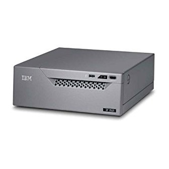
Product introduction March 2009 Figure 2. Front view of 4810/4910 system unit These are the descriptions of the indicators that are on the front cover: This indicates a standard USB port. This LED indicates HDD activity. This LED indicates the 4810 power state. Hold down the power button for 4 seconds to power off. -
Page 20: Rear Connectors
Product introduction March 2009 Rear connectors Figure 3 and Figure 4 show examples of the rear view of the 4810/4910 model x4x. Figure 3. Rear view of the 4810/4910 model x4x (RS232) Figure 4. Rear view of the 4810/4910 model x4x (USB) Table 6. - Page 21 This symbol indicates the location where a security screw can be optionally installed by a customer to protect access to the inside of the system unit. (IBM does not provide this screw.) The screw is an M3 and can protrude into the unit for 6 to 9 mm. The screw head needs to be a pan head or the equivalent.
- Page 22 Product introduction March 2009 SurePOS Installation and Service...
-
Page 23: Chapter 2. Getting Started
Preload features: ® v Windows XP ® v Windows Embedded for Point of Service (WEPOS) Refer to IBM 4810/4910 SurePOS 300 Operating System Installation Guide for information about installing other operating systems. © Copyright IBM Corp. 2005, 2009... - Page 24 March 2009 SurePOS Installation and Service...
-
Page 25: Chapter 3. Removal And Installation Procedures For The 4810/4910 Surepos 300
“Removing and installing the hard disk drive air duct” on page 22 v “Removing and installing the battery” on page 23 v “Removing and installing the system board” on page 25 v “Removing and installing the front cover” on page 27 © Copyright IBM Corp. 2005, 2009... -
Page 26: Removing And Installing The Top Cover
March 2009 Removing and installing the top cover Figure 5. Removing and installing the top cover To open the top cover: 1. Switch OFF the power to the unit. Unplug the power cord from the system unit. 2. Attention: Establish personal grounding before touching this unit. 3. -
Page 27: Service Label
March 2009 Figure 6. Service label To replace the top cover: 1. Place the top cover so that it is approximately 15 mm (5/8 in.) from the front of the unit. 2. Slide the top forward until the latches make a clicking noise and are engaged. Check both side latches to ensure that both latches are fully latched and appear to align up evenly with the sides of the top cover. -
Page 28: Removing And Installing The Hard Disk Drive
March 2009 Removing and installing the hard disk drive This section describes how to remove, install and replace the hard drive unit. To remove the hard drive and the hard drive tray as an assembly, see “Removing and installing the hard disk drive and hard disk tray as an assembly” on page 15. Note: The hard drive assembly might not be installed on a unit where the modular flash drive is installed instead. -
Page 29: Removing And Installing The Hard Disk Drive And Hard Disk Tray As An Assembly
March 2009 Removing and installing the hard disk drive and hard disk tray as an assembly Figure 8. Removing the hard drive and hard drive tray as an assembly To remove the hard drive and tray as an assembly: v Open the unit. See “Removing and installing the top cover” on page 12. v Grasp the tray assembly 1 where the arrows originate 2 . -
Page 30: Removing And Installing The Flash Drive
March 2009 Removing and installing the flash drive Figure 9. Removing the flash drive To remove the flash drive or to access the system board to install a flash drive: 1. Open the unit. See “Removing and installing the top cover” on page 12. 2. -
Page 31: Removing And Installing The Memory Module
March 2009 Removing and installing the memory module Figure 10. Opening the memory-module retainer clips Figure 11. Memory-module retainer clips in the open position. To remove the memory module: 1. Open the unit. See “Removing and installing the top cover” on page 12. 2. -
Page 32: Removing And Installing The Front-Panel Card
March 2009 Removing and installing the front-panel card Figure 14. Removing and replacing the front-panel card To remove the front-panel card: 1. Open the unit. See “Removing and installing the top cover” on page 12. 2. Remove the hard drive and tray assembly. See “Removing and installing the hard disk drive and hard disk tray as an assembly”... -
Page 33: Removing And Installing The I/O Connector Card
March 2009 Removing and installing the I/O connector card Figure 15. Removing the I/O connector card To remove the I/O connector card: 1. Open the unit. See “Removing and installing the top cover” on page 12. 2. Squeeze the blue plastic connector-card retainer at the top and bottom (where the two small arrows 3 are located in Figure 15) to unlatch. -
Page 34: Removing And Installing The Riser Card And The I/O Connector Card As An Assembly
March 2009 Removing and installing the riser card and the I/O connector card as an assembly Figure 16. Removing the riser card and the I/O connector card as an assembly To remove the riser card and the I/O connector card as an assembly: 1. -
Page 35: Removing And Installing The Power Supply
March 2009 Removing and installing the power supply Figure 17. Removing the power supply To remove the power supply: 1. Open the unit. See “Removing and installing the top cover” on page 12. Note: The HDD tray can remain in place. 2. -
Page 36: Removing And Installing The Hard Disk Drive Air Duct
March 2009 Removing and installing the hard disk drive air duct Figure 18. Removing the hard drive air duct Attention: The hard drive front air duct must be installed correctly to allow the flow of air for the hard drive; incorrect installation can result in hard drive failure. The hard disk drive air duct should not be removed unless it is broken or installed improperly. -
Page 37: Resetting The System Board Cmos Settings
March 2009 Resetting the system board CMOS settings Figure 19. Locating and resetting the CMOS jumper Follow these steps to reset the system board CMOS to the default settings: 1. Open the unit. See “Removing and installing the top cover” on page 12. 2. -
Page 38: Removing And Installing The Battery
March 2009 Figure 20. Removing and installing the battery 1. Open the unit. See “Removing and installing the top cover” on page 12. 2. Remove the battery 1 by sliding it up in the direction of the arrow as shown. 3. -
Page 39: Removing And Installing The System Board
March 2009 Removing and installing the system board Figure 21. Removing the system board To remove the system board: 1. Open the unit. See “Removing and installing the top cover” on page 12. 2. Remove the hard drive assembly. See “Removing and installing the hard disk drive and hard disk tray as an assembly”... - Page 40 March 2009 8. Remove the system board by tilting it 4 as shown in Figure 22; then lift up Figure 22. Tilting and removing the system board 9. To install the system board, reverse this procedure. Note: Be sure the system board is aligned with the 4 screw holes correctly before installing the 4 retaining screws.
-
Page 41: Removing And Installing The Front Cover
March 2009 Removing and installing the front cover Figure 23. Removing the front cover To remove the front cover: 1. Open the unit. See “Removing and installing the top cover” on page 12. 2. Remove the hard drive assembly. See “Removing and installing the hard disk drive and hard disk tray as an assembly”... - Page 42 March 2009 SurePOS Installation and Service...
-
Page 43: Chapter 4. Problem Determination
1. Obtain a memory key. See “Supported memory keys” described above. 2. Access the IBM Retail Store Solutions Web site at: www.ibm.com/solutions/ retail/store/support. 3. Select Support on the left side of the panel, then select IBM SurePOS 300 Series. 4. Next, select SurePOS 300-34x Downloads. -
Page 44: Troubleshooting
This program writes the updates and provides instructions on inserting the memory key. 6. In most cases, the Diagnostics key should boot on the IBM SurePOS 300 unit by inserting the USB memory key into the unit and then powering ON the system. -
Page 45: Power Led Operation
Problem determination March 2009 2. Verify that any externally-powered I/O devices connected to an AC power outlet are operating correctly and that the devices are powered ON. 3. Verify that the contrast and brightness controls on the video display (if attached) are set correctly. -
Page 46: Symptoms
Problem determination March 2009 Table 9. POST messages displayed to the system monitor Message Meaning/Action Hard Disk S.M.A.R.T. Failure The hard disk is reporting an internal error that may result in the loss of data. It is recommended that all relevant data on the drive be moved to a safe storage media. - Page 47 Problem determination March 2009 Table 10. 4810/4910 Problem symptoms table (continued) Symptom Actions System Getting Blue Screens Often, blue screens are caused by OS, driver, or application software issues. Diagnosing blue screens should be handled through a software diagnostic path. To determine if the hardware has contributed to a blue screen situation, run the system unit diagnostics, including running the extended diagnostics for the...
-
Page 48: Suspected Fault
Problem determination March 2009 Table 10. 4810/4910 Problem symptoms table (continued) Symptom Actions Cash Drawer not working Note: The cash drawer port is located on the riser card. 1. Boot the RSS diagnostics memory key. 2. Choose the POS I/O tests from the main screen. Check to see if the cash drawer test appears on the screen;... - Page 49 Problem determination March 2009 Table 11. Suspected Fault Table (continued) Evaluation Modular Flash Drive Run the system unit tests. Does the system unit test identify the modular flash drive as an option? No – Replace the flash drive. Yes – Run the test for the modular flash drive. Does the test pass? No –...
- Page 50 Problem determination March 2009 Table 11. Suspected Fault Table (continued) Evaluation IO Connector Card Latch Physical examination. Top Cover Physical examination. SurePOS Installation and Service...
-
Page 51: Chapter 5. Parts Catalog
Assembly 1: Field-replaceable units ....38 This chapter provides parts information available for the Model x4x system units. See the hardware service guide for each peripheral device for parts information about the device. © Copyright IBM Corp. 2005, 2009... -
Page 52: Assembly 1: Field-Replaceable Units
Parts catalog March 2009 Assembly 1: Field-replaceable units SurePOS Installation and Service... - Page 53 Assembly 1: (continued) March 2009 Asm– Part Index Number Units Description 1– 4810/4910 System Unit Assembly –1 44V2034 1 Top cover –2 44V2031 1 Power supply –3 44V2036 1 Riser card assembly –4 44V2039 1 I/O Connector card latch –5 44V2025 1 SurePort Serial Connector card (RS232) –5...
- Page 54 Assembly 1: (continued) March 2009 SurePOS Installation and Service...
-
Page 55: Chapter 6. Power Cords
Chile, 2.8 meter non-locking 39M5065 Argentina, 2.8 meter non-locking 39M5099 Australia, 2.8 meter non-locking 39M5078 Columbia, 2.8 meter non-locking 39M5230 Brazil, 2.8 meter non-locking Note: Unless otherwise indicated, all power cords are 4.3 meter (14.1 feet) non-locking. © Copyright IBM Corp. 2005, 2009... - Page 56 March 2009 SurePOS Installation and Service...
-
Page 57: Appendix A. Connector Pinouts
March 2009 Appendix A. Connector Pinouts Keyboard/Mouse Connector Figure 24. Keyboard/Mouse Connector Table 13. Keyboard/Mouse Connector Signal Keyboard Data Mouse Data Ground Keyboard Clock Mouse Clock © Copyright IBM Corp. 2005, 2009... -
Page 58: Rs232 Connector
March 2009 RS232 Connector Figure 25. RS232 Connector Table 14. RS232 Connector Signal Direction Carrier Detect (DCD) Input Received Data (RxD) Input Transmitted Data (TxD) Output Data Terminal Ready (DTR) Output Common Ground Data Set Ready (DSR) Input Request to Send (RTS) Output Clear to Send (CTS) Input... -
Page 59: Powered Rs232 Connector
March 2009 Powered RS232 Connector Figure 26. Powered RS232 Connector Table 15. Powered RS232 Connector Signal Direction Output Received Data (RxD Input Transmitted Data (TxD) Output Data Terminal Ready (DTR) Output Common Ground Data Set Ready (DSR) Input Request to Send (RTS) Output Clear to Send (CTS) Input... -
Page 60: External Vga Connector
March 2009 External VGA Connector Figure 27. External VGA Connector Table 16. External VGA Connector Signal GREEN BLUE Ground RED Ground GREEN Ground BLUE Ground Ground SDA (I HSync VSync SCL (I SurePOS Installation and Service... -
Page 61: Ethernet Connector
March 2009 Ethernet Connector Figure 28. Ethernet Connection Table 17. Ethernet Connector 10/100Base-T Signal 10/100Base-T Direction TxD+ Output TxD- Output RxD+ Input RxD- Input USB Connector Figure 29. USB Connector Table 18. USB Connector Connector 5V VBus -Data +Data Ground Appendix A. -
Page 62: Headphone/Line-In/Microphone Connector
March 2009 Headphone/Line-in/Microphone Connector Table 19. Headphone/Line-in/Microphone Connector Signal Left channel audio Ring Right channel Audio Base Ground Cash Drawer Connector Figure 30. Cash Drawer Connector Table 20. Cash Drawer Connector Connector Ground Sense Open SurePOS Installation and Service... -
Page 63: Powered Usb Connector
March 2009 Powered USB Connector Figure 31. Powered USB Connector Table 21. Powered USB Connector Connector 5V VBus -Data +Data Ground Ground 12V or 24V 12V or 24V Ground Appendix A. Connector Pinouts... - Page 64 March 2009 SurePOS Installation and Service...
-
Page 65: Appendix B. Safety Information
March 2009 Appendix B. Safety information Danger: Before you begin to install this product, read the safety information in IBM Safety Information — Read This First, GA27-4004. This booklet describes safe procedures for cabling and plugging in electrical equipment. Gevaar: Voordat u begint met de installatie van dit produkt, moet u eerst de veiligheidsinstructies lezen in de brochure Veiligheidsinstructies—Lees dit... - Page 66 Gevaar Voordat u begint met het installeren van dit produkt, dient u eerst de veiligheidsrichtlijnen te lezen die zijn vermeld in de publikatie IBM Safety Information — Read This First, GA27-4004. In dit boekje vindt u veilige procedures voor het aansluiten van elektrische appratuur.
- Page 67 March 2009 Vigyázat Mielôtt megkezdi a berendezés üzembe helyezését, olvassa el a IBM Safety Information — Read This First, GA27-4004 könyvecskében leírt biztonsági információkat. Ez a könyv leírja, milyen biztonsági intézkedéseket kell megtenni az elektromos berendezés huzalozásakor illetve csatlakoztatásakor. Pericolo prima di iniziare l’installazione di questo prodotto, leggere le informazioni...
- Page 68 March 2009 Peligro Antes de empezar a instalar este producto, lea la información de seguridad en Información de Seguridad—Lea Esto Primero, GA27-4004. Este documento describe los procedimientos de sequridad para cablear y enchufar equipos eléctricos. Varning—livsfara Innan du börjar installera den här produkten bör du läsa säkerhetsinformationen i dikumentet Säkerhetsföreskrifter—Läs detta först, GA27-4004.
- Page 69 March 2009 GA27-4004 GA27-4004 Appendix B. Safety information...
- Page 70 March 2009 GA27-4004 GA27-4004 GA27-4004 GA27-4004 GA27-4004 GA27-4004 SurePOS Installation and Service...
-
Page 71: Appendix C. Notices
IBM may use or distribute any of the information you supply in any way it believes appropriate without incurring any obligation to you. Any references in this information to non-IBM Web sites are provided for convenience only and do not in any manner serve as an endorsement of those Web sites. - Page 72 IBM has not tested those products and cannot confirm the accuracy of performance, compatibility or any other claims related to non-IBM products. Questions on the capabilities of non-IBM products should be addressed to the suppliers of those products.
-
Page 73: Electronic Emission Notices
Properly shielded and grounded cables and connectors must be used in order to meet FCC emission limits. IBM is not responsible for any radio or television interference caused by using other than recommended cables and connectors or by unauthorized changes or modifications to this equipment. -
Page 74: Industry Canada Class A Emission Compliance Statement
In solch einem Fall ist der Abstand bzw. die Abschirmung zu der industriellen Störquelle zu vergröβern.″ Anmerkung: Um die Einhaltung des EMVG sicherzustellen sind die Geräte, wie in den IBM Handbüchern angegeben, zu installieren und zu betreiben. Australia and New Zealand Attention: This is a Class A product. -
Page 75: Chinese Class A Warning Statement
March 2009 Chinese Class A warning statement Attention: This is a Class A product. In a domestic environment this product may cause radio interference in which case the user may be required to take adequate measures. Japanese power line harmonics compliance statement Japanese Voluntary Control Council for Interference (VCCI) statement Attention: This product is a Class A Information Technology Equipment and... -
Page 76: Taiwanese Class A Warning Statement
March 2009 Taiwanese Class A warning statement Taiwan contact information IBM Taiwan Product Service Contact Info: IBM Taiwan Corporation 3F, No 7, Song Ren Road, Taipei Taiwan Telephone: 0800-016-888 Cable ferrite requirement All cable ferrites are required to suppress radiated EMI emissions and must not be removed. -
Page 77: Product Recycling And Disposal
(TI) que reciclen responsablemente sus equipos cuando éstos ya no les sean útiles. IBM dispone de una serie de programas y servicios de devolución de productos en varios países, a fín de ayudar a los propietarios de equipos a reciclar sus productos de TI. -
Page 78: Battery Return Program
United States, go to http://www.ibm.com/ibm/environment/ products/batteryrecycle.shtml or contact your local waste disposal facility. In the United States, IBM has established a return process for reuse, recycling, or proper disposal of used IBM sealed lead acid, nickel cadmium, nickel metal hydride, and other battery packs from IBM equipment. -
Page 79: For The European Union
For proper collection and treatment, contact your local IBM representative. This notice is provided in accordance with Royal Decree 106/2008 of Spain: The retail price of batteries, accumulators and power cells includes the cost of the environmental management of their waste. -
Page 80: Flat Panel Displays
Trademarks The following are trademarks of International Business Machines Corporation in the United States or other countries, or both: AnyPlace Kiosk(tm) AnyPlace POS Hub(tm) DB2 Universal Database IBM and the IBM logo PS/2 SureMark SurePoint SurePOS Wake on LAN WebSphere Microsoft, Windows, Windows NT, and the Windows logo are trademarks of Microsoft Corporation in the United States, other countries, or both. -
Page 81: Index
Taiwan 62 battery recycling 64 electrostatic discharge (ESD) 62 cable ferrites 62 end of life disposal 63 electronic emissions 59 equipment disposal 63 electrostatic discharge (ESD) 62 end of life disposal 63 IBM 57 © Copyright IBM Corp. 2005, 2009... - Page 82 March 2009 opening the unit 12 parts catalog, FRUs 37 perchlorate 65 physical dimensions 2 power cords 41 power supply, removal 21 preliminary checklist 30 problem determination 29 tools 29 problem symptoms 32 product overview 1 rear connectors 6 removal and replacement battery 23 flash drive 16 front cover 27...
-
Page 83: Part Number Index
44V2035 1–13 44V2036 1–3 44V2037 1–14 44V2038 1–11 44V2039 1–4 44V2040 1–12 44V2041 1–9 44V2047 1– 44V2048 1– 44V2049 1– 44V2050 1– 44V2051 1– 44V2052 1– 44V2053 1– 44V2078 1– 44V2079 1– 45P6222 1–10 © Copyright IBM Corp. 2005, 2009... - Page 84 March 2009 SurePOS Installation and Service...
- Page 85 When you send comments to IBM, you grant IBM a nonexclusive right to use or distribute your comments in any way it believes appropriate without incurring any obligation to you. IBM or any other organizations will only use the personal information that you supply to contact you about the issues that you state on this form.
- Page 86 UNITED STATES BUSINESS REPLY MAIL FIRST-CLASS MAIL PERMIT NO. 40 ARMONK, NEW YORK POSTAGE WILL BE PAID BY ADDRESSEE IBM Corporation Retail Store Solutions Information Development, Dept ZBDA P. O. Box 12195 RESEARCH TRIANGLE PARK NC 27709-9990 _ _ _ _ _ _ _ _ _ _ _ _ _ _ _ _ _ _ _ _ _ _ _ _ _ _ _ _ _ _ _ _ _ _ _ _ _ _ _ _ _ _ _ _ _ _ _ _ _ _ _ _ _ _ _ _ _ _ _ _ _ _ _ _ _ _ _ _ _ _ _ _ _ _ _ _ _ _ _ _ _ _ _ _ _ _ _ _ _...
- Page 88 March 2009 Printed in USA G362-0560-00...
Need help?
Do you have a question about the 4810-E3H and is the answer not in the manual?
Questions and answers