Table of Contents

Related Manuals for Extron electronics TP Receivers Family


Summary of Contents for Extron electronics TP Receivers Family
- Page 1 User’s Manual Do not connect this device to a computer data or telecommunications network TP Receivers Family High Resolution Video, Composite Video, and Stereo Audio Twisted Pair Cable Transmission Products 68-547-02 Rev. L 01 10...
- Page 2 Precautions Safety Instructions • English Warning Power sources • This equipment should be operated only from the power source This symbol is intended to alert the user of important indicated on the product. This equipment is intended to be used with a main power operating and maintenance (servicing) instructions in system with a grounded (neutral) conductor.
- Page 3 Precautions, cont’d 安全须知 • 中文 警告 电源 • 该 设 备 只 能 使 用 产 品 上 标 明 的 电 源 。 设 备 这个符号提示用户该设备用户手册中 必 须 使 用 有 地 线 的 供 电 系 统 供 电 。 第 三 条 线 有重要的操作和维护说明。...
-
Page 5: Table Of Contents
Table of Contents Chapter One • Introduction .......... 1-1 About the TP Receivers ............. 1-2 Features .................. 1-4 TP R BNC A receiver .............. 1-4 TP R BNC AV receiver ............ 1-5 TP R 15HD A receiver ............ 1-5 Chapter Two • Installation and Operation .... 2-1 Installation Overview ............ 2-2 Video jumpers .............. - Page 6 Table of Contents, cont’d All trademarks mentioned in this manual are the properties of their respective owners. 68-547-02 Rev. L 01 10 TP Receivers • Table of Contents...
-
Page 7: Chapter One • Introduction
TP Receivers Chapter One Introduction About the TP Receivers Features... -
Page 8: About The Tp Receivers
Introduction Introduction, cont’d About the TP Receivers The TP R BNC A, TP R BNC AV, and TP R 15HD A are Extron Twisted Pair (TP) receivers that receive transmissions of RGB video, component video, S-video, composite video, and stereo audio over Extron Enhanced Skew-Free A/V UTP cable or ™... -
Page 9: Video Format
Recommended transmission ranges at 60 Hz, TP R BNC A and TP R BNC AV Maximum range Maximum range Video format (High Quality) (Variable Quality) Component, S-video, Composite 1000 feet (304 m) 1050 feet (320 m) video and audio 640 x 480 1000 feet (304 m) 1050 feet (320 m) 800 x 600... -
Page 10: Features
Introduction, cont’d Features All Extron TP receivers provide the following features: Audio output — Provides unbalanced (left/right) audio on RCA connectors, and balanced or unbalanced audio on 3.5 mm, 5-pole captive screw connectors. Level control — Allows manual control of image brightness. Peaking control —... -
Page 11: Tp R Bnc Av Receiver
TP R BNC AV receiver The TP R BNC AV receiver has the following features: Video output — Provides RGBHV, RGBS, or RGsB video on 5 BNC connectors, and composite video on 1 BNC connector. RJ-45 connector — Allows attachment to an Extron TP transmitter. - Page 12 Introduction, cont’d This page intentionally left blank. TP Receivers • Introduction...
-
Page 13: Installation And Operation
TP Receivers Chapter Two Installation and Operation Installation Overview Front Panel Controls and Indicators Troubleshooting... -
Page 14: Installation Overview
Installation and Operation, cont’d Installation and Operation Installation Overview To install and set up a TP receiver and the associated TP transmitter(s) for operation, perform the following steps: Disconnect power from all of the equipment, including the video source, (such as computers or DVD players), the transmitter, receiver, and output displays. - Page 15 The following transmitters are compatible with the TP R 15HD A, TP R BNC A and TP R BNC AV receivers: TP T 15HD 45, TP T A 45, TP T 15HD A, TP T 15HD AV, All TP transmitters include a 15 V or 12 V external power supply. The transmitters (with the exception of the TP T 15HD 45 and TP T A 45) also receive power from the associated Extron TP receiver(s) (with the exception of the TP R 15HD A) via the TP cable. Extron recommends using the local power supply; however, the power supply may not be necessary in some applications. Use the following guidelines: • The TP T 15HD A and TP T 15HD AV may not require a local power supply for cable lengths of 300 feet or less. • All of the following transmitters require the local power supply: TP T BNC DA4 TP T 15HD 45 TP T A 45 VTT001 ...
-
Page 16: Video Jumpers
Installation and Operation, cont’d Video jumpers The TP R BNC A and TP R BNC AV receivers can be configured to receive component video (bi-level sync only), S-video, or composite video. The receivers are factory configured for RGB video. To receive any other type of video, reconfigure the jumpers. Remove the three screws on each side and the two screws on top of the cover (figure 2-1). -
Page 17: Video Dip Switch
Locate J3 on the RGB video printed circuit board. See figure 2-1. For RGB video, ensure that pin 2 is jumpered to pin 3. For any other video format, ensure that pin 1 is jumpered to pin 2. Reinstall the video board, replace the cover, and reinstall the screws and BNC connector hex nuts. - Page 18 Installation and Operation, cont’d Shift internal jumpers as follows: Remove three screws on each side and two screws on top of the cover (figure 2-2). Remove 8 Screws 1 .3 Lift Cover 0 -2 Straight Up TP R BNC AV /6 0 V I D Remove 5 (TP R BNC A)
-
Page 19: Mounting The Receiver
Mounting the receiver UL guidelines for rack mounting The following Underwriters Laboratories (UL) guidelines are relevant to the safe installation of the TP Receivers in a rack: Elevated operating ambient temperature — If the unit is installed in a closed or multi-unit rack assembly, the operating ambient temperature of the rack environment may be greater than room ambient temperature. -
Page 20: Rack Mounting (Tp R Bnc A, Tp R Bnc Av, Tp R 15Hd
Installation and Operation, cont’d Rack mounting (TP R BNC A, TP R BNC AV, TP R 15HD A) TP R BNC A, TP R BNC AV, or TP R 15HD AV — For optional rack mounting, mount the receiver on a Universal Rack Shelf Kit for 9.5 inch deep products (Extron part #60-190-01) (figure 2-3). - Page 21 TP R 15HD A only — For optional rack mounting, mount the receiver on a Rack Shelf Kit for 3.5 inch deep products (Extron part #60-190-20), figure 2-4. The TP R 15HD A mounts in one of four locations on the rack. 3.5”...
-
Page 22: Furniture Mounting
Installation and Operation, cont’d Furniture mounting All receiver models can be mounted under furniture such as a table or podium surface using the appropriate optional mounting bracket; the Extron Under-Desk Mounting Kit for 1/8 and 1/4 Rack Width Products (part #70-212-01) (TP R 15 HD A) or Under-Desk Mounting Kit for 1/2 Rack Width Products (part #70-077-01) (all other models). -
Page 23: Projector Mounting
For through-surface mounting (all except TP R 15HD A), insert four #8 wood screws through the bracket and into the four pilot holes. Tighten all four screws to secure the receiver in place. For under-surface mounting, insert #8 wood screws into the four pilot holes. -
Page 24: Rear Panel Features And Cabling
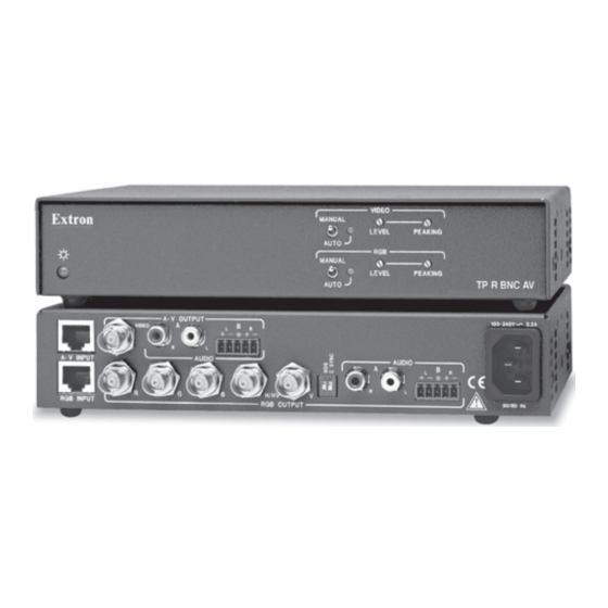
Installation and Operation, cont’d Rear panel features and cabling A-V AUDIO VIDEO 100-240V 0.3A A-V INPUT AUDIO AUDIO H/HV RGB INPUT RGB OUTPUT 50/60 Hz TP R BNC AV AUDIO POWER 15V .5A DC H/HV RGB INPUT RGB OUTPUT TP R BNC A AUDIO POWER .34A MAX... -
Page 25: Output Cabling
Composite video input connector — Attach one end of a TP cable to this RJ-45 female connector. Attach the other end to an Extron TP video transmitter outputting composite video. See Termination of TP cable on page 2-17 for pin assignments. Output cabling Computer video The TP R BNC A, TP R BNC AV, and TP R 15HD A receive and output RGB video. -
Page 26: Composite Video
Installation and Operation, cont’d RGB Output 15HD (TP R 15HD A) — Connect the desired video output device to the rear panel output 15HD connector. Refer to the table below for the video signal connections. Pins 13 and 14 are for sync only. Pin# Description Component S-Video... -
Page 27: Audio
Audio All TP receivers receive and output stereo audio. The TP R BNC A and AV output audio on both left and right RCA connectors ( ) and on 3.5 mm, 5-pole captive screw connectors ( ). The TP R 15HD A outputs audio on the captive screw connector ( ) only. -
Page 28: Power Connector
Installation and Operation, cont’d Power connector Power TP R BNC AV — Plug a standard IEC power cord into this connector to connect the TP R BNC AV to a 100 to 240 VAC, 50-60 Hz power source. If the distance between the transmitter and receiver is too great for the receiver to power the transmitter, the video image will be missing, distorted, noisy, or the receiver Manual/Auto LED will flash. The transmitter will require a local power supply. -
Page 29: Termination Of Tp Cable
Termination of TP cable Figure 2-10 details the termination of TP cables in accordance with the TIA/EIA T 568 A wiring standards. Pins: RJ-45 12345678 connector RGB video and audio AV Video and audio Wire color Signal Level Signal Level 1 White-green Red/V. -
Page 30: Cable Testing
Installation and Operation, cont’d Cable testing The TP units are designed for and perform best with Extron Enhanced Skew-Free A/V cable terminated in accordance with the TIA/EIA T 568 A wiring standard. CAT 5, Cat 5e and Cat 6 cables are acceptable but less preferable. Extron also recommends the use of pre-terminated and tested cables. - Page 31 TP T 15HD A IF cable measurement indicates the pair with wires 1 and 2 is D IO four feet shorter than the other pairs... H -S Audio H IF IT O V .5 D IO TP R BNC A H /H PC Computer CAT 5 UTP Cable...
-
Page 32: Front Panel Controls And Indicators
Installation and Operation, cont’d Front Panel Controls and Indicators The TP R Receivers have similar controls and indicators as shown below. MANUAL LEVEL PEAKING AUTO TP R BNC A VIDEO MANUAL LEVEL PEAKING AUTO MANUAL LEVEL PEAKING TP R BNC AV AUTO Figure 2-12 —... -
Page 33: Troubleshooting
• The receiver is connected through a TP switcher to a device that provides a reference ground. Manual/Auto switch (TP R BNC A and TP R BNC AV) — With this switch in the Auto position, the receiver automatically adjusts level and peaking to compensate for long cable runs. In the Manual position, compensate for long cable runs using the level and peaking controls. -
Page 34: If The Image Is Not Displayed Correctly
Installation and Operation, cont’d The transmission distance may be too short. Ensure the UTP cable is at least 50 feet long. If the Manual/Auto switch is in the manual position, ensure the receiver level controls are not set too high. Too much level and peaking can cause display problems. -
Page 35: Accessories, And Part Numbers
TP Receivers Appendix Specifications, Accessories, and Part Numbers Specifications Included Parts Extron Accessories Cables/Adapters ... -
Page 36: Video Output
Specifications, Accessories, and Part Numbers cont’d Specifications, Accessories, and Part Numbers Video Number/signal type ..... 1 or 2 sets of proprietary analog signals Connectors ........1 or 2 shielded RJ-45 female Video input— refer to the TP Transmitters Family User’s Manual, part #68-546-02 Video output Number/signal type TP R BNC A ...... -
Page 37: Audio Output
Audio Number/signal type ..... 1 or 2 sets of analog proprietary signals Connectors ........1 or 2 shielded RJ-45 female Frequency response ...... 20 Hz to 20 kHz, >±0.05 dB THD + Noise ........0.03% @ 1 kHz, 0.3% @ 20 kHz at maximum output (unweighted) S/N .......... - Page 38 Specifications, Accessories, and Part Numbers cont’d Power input requirements TP R BNC A ......15 VDC, 0.3 A (minimum) TP R 15HD A ...... 15 VDC, 0.34 A (maximum) Temperature/humidity ....Storage -40° to +158°F (-40° to +70°C) / 10% to 90%, noncondensing Operating +32°...
- Page 39 Product weight TP R BNC A ......1.6 lbs (0.7 kg) TP R BNC AV ..... 2.6 lbs (1.2 kg) TP R 15HD A ...... 0.4 lbs (0.2 kg) Shipping weight TP R BNC A ......4 lbs (2 kg) TP R BNC AV .....
- Page 40 Specifications, Accessories, and Part Numbers cont’d Included Parts These items are included in each order for a specific TP receiver: Included parts Part number TP Receiver Set up Guide Captive screw connector, 5 pole, 3.5 mm (1 or 2) 100-457-01 TP R BNC A 60-351-02 Single output external power supply, 15 V, 0.8 A...
- Page 41 Extron Accessories Accessories Part number PS 150 Multiple output 15 V power supply 60-432-01 RSU 129, Universal Rack Shelf for 9.5 inch deep 60-190-01 products RSB 129, Basic Rack Shelf for 9.5 inch deep products, Gray 60-604-02 RSU 126, Universal Rack Shelf for 6 inch deep 60-190-10 products RSB 126, Basic Rack Shelf for 6 inch deep products...
- Page 42 Specifications, Accessories, and Part Numbers cont’d Enhanced Skew-Free A/V UTP Cables Part number ™ UTP23SF-4/3 (3 feet/90 cm) 26-569-01 UTP23SF-4/6 (6 feet/1.0 m) 26-569-02 UTP23SF-4/12 (12 feet/3.6 m) 26-569-03 UTP23SF-4/25 (25 feet/7.6 m) 26-569-04 UTP23SF-4/35 (35 feet/10.6 m) 26-569-05 UTP23SF-4/50 (50 feet/15.2 m) 26-569-06 UTP23SF-4/75 (75 feet/22.8 m) 26-569-07...
- Page 43 In no event will Extron Electronics be liable for direct, indirect, or consequential damages resulting from any defect in this product even if Extron Electronics has been advised of such damage.
- Page 44 Inside USA / Canada Only Inside Europe Only Inside Asia Only Inside China Only Inside USA / Canada Only +1.919.863.1794 +31.33.453.4040 +65.6383.4400 +86.21.3760.1568 +1.714.491.1500 +1.919.863.1797 FAX +31.33.453.4050 FAX +65.6383.4664 FAX +86.21.3760.1566 FAX +1.714.491.1517 FAX © 2010 Extron Electronics. All rights reserved.
Need help?
Do you have a question about the TP Receivers Family and is the answer not in the manual?
Questions and answers