Table of Contents
Advertisement
Quick Links
MTP 15HD RS Series • Setup Guide
This guide provides instructions for setting up and operating any of the Extron MTP 15HD RS transmitters and receivers.
4
M T P T 1 5 H D R S
RS-232
PRE-PEAK
POWER
Tx Rx
12V
ON
.5A MAX
OFF
INPUT
MONITOR
1
2
3
5
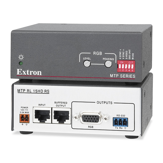
Transmitter and Receiver Rear Panels
Figure 1.
Pre-Installation — RS-232 DIP Switch
The RS-232 circuits of the receiver are factory-set to be one-way, transmitter to receiver.
If the system has only one receiver, the BI-232 DIP switch on the front panel of the receiver
can be set for two-way communication as explained in step 5 of "Installation".
Installation
1.
Turn off all MTPs and devices.
Turn the input and output devices off and unplug their power cords. Verify that all MTPs
are disconnected from power sources before proceeding.
2.
Connect the transmitter inputs.
•
Connect a VGA video source to the Input connector (
•
Connect a VGA monitor to the Monitor connector (
•
Connect an RS-232 control device into the RS-232 connector (
Wire the connector as shown in figure 2.
Terminate and connect TP cables between units.
3.
•
Connect a TP cable between the Output connector (
g
connector (
) of the receiver. Terminate the cable identically with either standard as shown
in figure 3.
•
For daisy-chaining, connect up to eight receivers using TP cables between the Buffered
Output connector (
daisy-chained receiver.
4.
Connect the receiver outputs.
•
Connect a VGA display to the Output connector (
•
Connect an RS-232 control device into the RS-232 connector (
Wire the RS-232 connector as shown in figure 2.
Configure the receiver DIP switches.
5.
See figure 4 for DIP switch (located on the front panel of the receiver) layout and settings.
•
H Sync + and V Sync + switches — Set these switches On (up) for positive sync
or Off (down) for negative sync.
•
S-Video switch — Set this switch ON (up) to output chroma on pin 3 and luma on pin 2.
Set this switch OFF (down) to output chroma on pin 1 and luma on pin 2.
•
End Unit switch — Set this switch On (up) if either of the following is true:
The receiver being configured is the only receiver connected to the transmitter.
•
The receiver being configured is the last receiver in a daisy-chained system.
•
:
NOTE
configured if there are one or more receivers connected to the
Buffered Output RJ-45 connector.
•
BI-232 switch — Set this switch ON (up) for bidirectional communication or
OFF (down) for unidirectional communication.
Terminate the power cable and ground the unit.
6.
ATTENTION:
See "Power Supply Wiring" in the user guide before wiring.
Wire the 2-pole captive screw connectors as shown in figure 5. Plug them into the Power
a
connectors (
) of the MTPs. The LED indicator on each MTP should be on when receiving power.
M T P R L 1 5 H D R S
BUFFERED
POWER
INPUT
OUTPUT
12V
.5A MAX
OUTPUT
OUTPUT
6
1
7
8
9
c
h
) of a receiver and the Input connector (
i
Set the End Unit switch Off (down) on the receiver being
OUTPUTS
RS-232
Tx
Rx
10
b
).
).
d
).
f
) of the transmitter and the Input
g
) of a
).
j
).
Product Category
Connected RS-232
Device Pins
Receive
Transmit
Ground
Figure 2.
RS-232 Connector Wiring
Pins:
12345678
T568A
Pin
Wire Color
Wire Color
1
White-green
White-orange
2
Green
Orange
3
White-orange
White-green
4
Blue
Blue
5
White-blue
White-blue
6
Orange
Green
7
White-brown
White-brown
8
Brown
Brown
Insert Twisted
Pair Wires
NOTE: If you are using Enhanced Skew-Free™
A/V cable, use the TIA/EIA T568A standard only.
Figure 3.
TP Termination Diagram
ON
1 2 3 4 5
Figure 4.
DIP Switches
POWER
12V
0.5A MAX
Smooth
Ridges
A
A
3/16"
(5 mm)
Max.
SECTION A–A
Power Supply
Output Cord
Figure 5.
Power Wiring and Grounding
MTP
Pins
Tx
Rx
G
T568B
Rear
Panel
Tie
Wrap
Ridges
Earth
Ground
1
Advertisement
Table of Contents

Related Manuals for Extron electronics MTP 15HD RS series


Summary of Contents for Extron electronics MTP 15HD RS series
- Page 1 Product Category MTP 15HD RS Series • Setup Guide This guide provides instructions for setting up and operating any of the Extron MTP 15HD RS transmitters and receivers. M T P R L 1 5 H D R S M T P T 1 5 H D R S...
- Page 2 Extron MTP 15HD RS products can be adversely affected by electrostatic discharge (ESD) if they are not grounded correctly. T o prevent malfunctions or product damage, an installer can correctly ground an Extron MTP 15HD RS series product by grounding the power input port.
Need help?
Do you have a question about the MTP 15HD RS series and is the answer not in the manual?
Questions and answers