Table of Contents

Related Manuals for Extron electronics TP Receivers


Summary of Contents for Extron electronics TP Receivers
- Page 1 User’s Manual Do not connect this device to a computer data or telecommunications network TP Receivers Family HIgh Resolution Video, Composite Video, and Stereo Audio Twisted Pair Cable Transmission Products 68-547-02 Rev. J 01 09...
- Page 2 Safety Instructions • English This symbol is intended to alert the user of important operating and maintenance (servicing) instructions in the literature provided with the equipment. This symbol is intended to alert the user of the presence of uninsulated dangerous voltage within the product’s enclosure that may present a risk of electric shock.
- Page 3 ( 地 线 ) 是 安 全 设 施 , 不 能 不 用 或 跳 过 。 拔掉电源 • 为安全地从设备拔掉电源,请拔掉所有设备后 或桌面电源的电源线,或任何接到市电系统的电源线。 电源线保护 • 妥善布线, 避免被踩踏,或重物挤压。 维护 • 所有维修必须由认证的维修人员进行。 设备内部 没有用户可以更换的零件。为避免出现触电危险不要自 己试图打开设备盖子维修该设备。 通风孔 • 有些设备机壳上有通风槽或孔,它们是用来防止 机内敏感元件过热。 不要用任何东西挡住通风孔。 锂电池 • 不正确的更换电池会有爆炸的危险。 必须使用 与厂家推荐的相同或相近型号的电池。 按照生产厂的 建议处理废弃电池。 TP Receivers...
- Page 4 TP Receivers...
-
Page 5: Table Of Contents
... 1-1 ... 1-2 ... 2-2 ... 2-9 ... 2-11 ... 2-12 ... 2-13 ... 2-13 ... 2-14 ... 2-15 ... 2-15 ... 2-17 ... 2-17 ... 2-20 TP Receivers • Table of Contents ... 2-1 . 2-8 ... 2-19... - Page 6 ... A-1 Specifications Included Parts Extron Accessories Cables/Adapters All trademarks mentioned in this manual are the properties of their respective owners. TP Receivers • Table of Contents ... A-2 ... A-6 ... A-6 ... A-7 68-547-02 Rev. J 01 09...
-
Page 7: Chapter One • Introduction
TP Receivers Chapter One Introduction About the TP Receivers Features... -
Page 8: About The Tp Receivers
Introduction Introduction, cont’d About the TP Receivers The TP R BNC A, TP R BNC AV and TP R 15HD are Extron Twisted Pair (TP) receivers that receive transmissions of RGB video, component video, S-video, composite video, and stereo audio over Extron Enhanced Skew-Free™ A/V UTP cable or... -
Page 9: Features
The TP receivers only receive signals transmitted by Extron TP transmitters. This user manual documents installation, features, and operation of the TP receivers only. For information about the TP transmitters, refer to the TP Transmitters Family User’s Manual, TP T 15HD 45 and TP T A 45 Manual, or the VTT001/TR001 Transmitter and Receiver Manual, as applicable, which accompanies the transmitters. -
Page 10: Tp R Bnc Av Receiver
#60-604-02). Mounts to a projector mounting bracket with the Extron Pole Mount Kit, PMK 200 (part #70-077-04). Mounts under or through furniture with an Extron Under-Desk Mounting Kit (part #70-077-01) or Through-Desk Mounting Kit (part #70-077-02). TP Receivers • Introduction... -
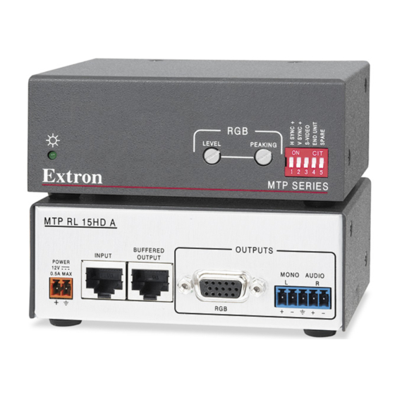
Page 11: Tp R 15Hd A Receiver
(part #60-604-20), a standard Universal 1U Universal Rack Shelf Kit (part #60-190-01) or 1U Basic Rack Shelf (part #60-604-02). Mounts under furniture or to a projector bracket with Extron’s optional mounting kits (part #70-212-01, furniture, or #70-217-01, projector). 1U Rack Shelf TP Receivers • Introduction... - Page 12 Introduction, cont’d This page intentionally left blank. TP Receivers • Introduction...
-
Page 13: Chapter Two • Installation And Operation
TP Receivers Chapter Two Installation and Operation Installation Overview Front Panel Controls and Indicators Troubleshooting... -
Page 14: Installation Overview
Connect power cords to the TP receiver, the TP transmitter, and turn on the video source(s) and the output display(s). TP Receivers • Installation and Operation The TP R BNC AV is a redesigned (modified) receiver. Audio jumpers configure the audio portion of the... - Page 15 Adjust the picture controls on the transmitter(s) and the receiver. See Controls and Indicators in this chapter and refer to the TP Transmitters Family User’s Manual, part #68-546-03. TP Receivers • Installation and Operation TP T A 45, TP T 15HD AV,...
-
Page 16: Video Jumpers
TP R BNC AV only: Remove the four screws securing the video board to the RGB board and lift the video board out of the way. TP Receivers • Installation and Operation The receivers are factory configured for RGB video. To receive any other type of video, reconfigure the jumpers. -
Page 17: Video Dip Switch
If using this receiver with an older, unmodified TP transmitter, and not planning to include a TPX 88 A in your system, set the receiver to receive audio on wire pair 7 and 8. Shift internal jumpers as follows: TP Receivers • Installation and Operation... - Page 18 Locate J10 and J11 on the composite video printed circuit board. See figure 2-2. Replace the cover, and reinstall the screws and BNC connector hex nuts. TP Receivers • Installation and Operation Remove 8 Screws Lift Cover Straight Up...
-
Page 19: Mounting The Receiver
UL guidelines for rack mounting The following Underwriters Laboratories (UL) guidelines are relevant to the safe installation of the TP Receivers in a rack: Elevated operating ambient temperature — If the unit is installed in a closed or multi-unit rack assembly, the operating ambient temperature of the rack environment may be greater than room ambient temperature. -
Page 20: Rack Mounting (Tp R Bnc A, Tp R Bnc Av, Tp R 15Hd A)
(2) 4-40 x 3/16" Screws Use 2 Mounting Holes on Opposite Corners Figure 2-3 — Rack mounting the TP R 15HD A and TP R BNC AV TP Receivers • Installation and Operation I N G I N G I N G V ID... -
Page 21: Furniture Mounting
Extron Under-Desk Mounting Kit for 1/8 and 1/4 Rack Width Products (part #70-212-01) (TP R 15 HD A) or Under-Desk Mounting Kit for 1/2 Rack Width Products (part #70-077-01) (all other models). TP Receivers • Installation and Operation IN G IN G IN G... - Page 22 For under-surface mounting, insert #8 wood screws into the four pilot holes. Tighten each screw into the mounting surface until slightly less than 1/4" of the screw protrudes. TP Receivers • Installation and Operation 2-10 V .5 D IO...
-
Page 23: Projector Mounting
(figure 2-6). Projector Mounting Bracket Figure 2-6 — Projector bracket mounting a receiver TP Receivers • Installation and Operation Mounting Bolt TP R 15HD A 2-11... -
Page 24: Rear Panel Features And Cabling
VIDEO A-V INPUT RGB INPUT RGB INPUT Figure 2-7 — Installation features, TP receivers Transmitted signal cabling RGB video transmission connector — Attach one end of a TP cable to this RJ-45 female connector (figure 2-7). Attach the other end to an Extron TP 15HD or BNC transmitter. See Termination of TP cable on page 2-15 for pin assignments. -
Page 25: Output Cabling
For S-video, use the R (C-chroma) and G (Y-luma) BNCs. For composite video, use the R, or G, or B BNC. -or- -or- The H/HV and V BNCs output sync, not video signals. TP Receivers • Installation and Operation H/HV H/HV H/HV H/HV... -
Page 26: Composite Video
The TP R BNC AV receives and outputs composite video. Video connector — Connect a composite video device to this rear panel BNC connector. Digital audio can also be connected through this connector. TP Receivers • Installation and Operation 2-14 Component R Return... -
Page 27: Audio
Audio All Extron TP receivers receive and output stereo audio. All receivers except the TP R 15HD A output the audio on both left and right RCA connectors and on 3.5 mm, 5-pole captive screw connectors. The TP R 15HD A outputs audio on the captive screw connector only. -
Page 28: Termination Of Tp Cable
2 3 4 5 6 7 8 1&2 3&6 4&5 Figure 2-10 — TP cable termination TP Receivers • Installation and Operation 2-16 this 3-pole captive screw connector (figure 2-9) and plug the connector into the receiver. The power supply is included with the unit. -
Page 29: Cable Testing
CAT 5e cable in A/V applications. The design of the Extron Enhanced Skew-Free A/V UTP cable reduces pair skew to the point that equalization is not required. TP Receivers • Installation and Operation 2-17... - Page 30 Pair RGB video 1, 2 Red 4, 5 Green 7, 8 Blue Figure 2-11 — Pair skew equalization TP Receivers • Installation and Operation 2-18 D IO IN P H -S H IF IT O CAT 5 UTP Cable ... THEN insert a four foot extension cable to equalize TP skew for red video.
-
Page 31: Front Panel Controls And Indicators
Green — indicates that a transmitter is connected and any of the following grounding conditions exist: • The transmitter is powered by a local power supply • The transmitter is powered by the receiver, is locally TP Receivers • Installation and Operation MANUAL LEVEL AUTO... -
Page 32: Troubleshooting
For computer video on an LCD projector, ensure the transmitter DDSP (Digital Display Sync Processing) switch is on. TP Receivers • Installation and Operation 2-20 • The transmitter is receiving power from the receiver, a local monitor is connected to the transmitter, and the receiver output is connected to a device that provides a reference ground. -
Page 33: If The Image Is Not Displayed Correctly
See Grounding the transmitter in the TP Transmitters Family User’s Manual, part #68-546-03. If the image still does not display properly, call the Extron Sales & Technical Support Hotline. TP Receivers • Installation and Operation Sales & Technical Support Hotline if 2-21... -
Page 34: If The Receiver Manual/Auto Led Flashes
If the receiver Manual/Auto LED flashes The transmission distance may be too far for remote power. Connect a local 15 V power supply to the transmitter. Check the RJ-45 connector for a loose connection. TP Receivers • Installation and Operation 2-22... -
Page 35: Numbers
TP Receivers Appendix Specifications, Accessories, and Part Numbers Specifications Included Parts Accessories Cables/Adapters... - Page 36 Nominal level ... 1 Vp-p for Y of component video and Minimum/maximum levels... 0.3 V to 1.45 Vp-p Impedance... 75 ohms Maximum resolution ... 1600x1200 TP Receivers • Specifications, Accessories, and Part Numbers video, or S-video; or 1 S-video and 1 NTSC/PAL/SECAM composite video from a single source; or...
-
Page 37: Audio Output
Power input requirements TP R BNC A ... 15 VDC, 0.3 A (minimum) TP R 15HD A... 15 VDC, 0.34 A (maximum) TP Receivers • Specifications, Accessories, and Part Numbers maximum output (unweighted) 1 stereo audio unbalanced 2 stereo audio unbalanced per input (1) 3.5 mm, 5-pole captive screw connector... - Page 38 TP R BNC AV ... 1.7" H x 8.75" W x 7.0" D (1U high, half TP R 15HD A... 1.6" H x 4.25" W x 3.0" D (1U high, quarter TP Receivers • Specifications, Accessories, and Part Numbers 10% to 90%, noncondensing Operating +32°...
- Page 39 EMI/EMC ... CE, C-tick, FCC Class A, ICES, VCCI MTBF... 30,000 hours Warranty ... 3 years parts and labor N All nominal levels are at ±10%. N Specifications are subject to change without notice. TP Receivers • Specifications, Accessories, and Part Numbers Transit Association)
-
Page 40: Extron Accessories
1U, 1/2 Rack Width, Through-Desk Mounting Kit, MBD 129 1U, Full Rack Width, Through-Desk Mounting Kit, MBD 149 1U, 1/2 Rack Width Pole Mount Kit, PMK 200 TP Receivers • Specifications, Accessories, and Part Numbers Part number 100-457-01 60-351-02 70-776-01... -
Page 41: Cables/Adapters
100' Enhanced Skew-Free A/V UTP Plenum 150' Enhanced Skew-Free A/V UTP Plenum 200' Enhanced Skew-Free A/V UTP Plenum 250' Enhanced Skew-Free A/V UTP Plenum 300' Enhanced Skew-Free A/V UTP Plenum TP Receivers • Specifications, Accessories, and Part Numbers Part number 22-141-03 22-142-03 100-476-01... - Page 42 S-video male to 2 BNC adapter, female, 8" S-video female to 2 BNC, male, 8" RG6 BNC/3 (3 feet/0.9 meters) RG6 BNC/6 (6 feet/1.8 meters) RG6 BNC/12 (12 feet/3.7 meters) TP Receivers • Specifications, Accessories, and Part Numbers Part number 26-260-15 26-260-01 26-260-02...
- Page 43 Extron Electronics warrants this product against defects in materials and workmanship for a period of three years from the date of purchase. In the event of malfunction during the warranty period attributable directly to faulty workmanship and/or materials, Extron Electronics will, at its option, repair or replace said products or components, to whatever extent it shall deem necessary to restore said product to proper operating condition, provided that it is returned within the warranty period, with proof of purchase and description of malfunction to:...
- Page 44 Extron USA - West Extron USA - East Extron Europe Headquarters +800.633.9876 +800.3987.6673 +800.633.9876 Inside USA / Canada Only Inside Europe Only Inside USA / Canada Only +1.919.863.1794 +31.33.453.4040 +1.714.491.1500 +1.919.863.1797 FAX +31.33.453.4050 FAX +1.714.491.1517 FAX © 2009 Extron Electronics. All rights reserved. Extron Asia Extron Japan Extron China...
Need help?
Do you have a question about the TP Receivers and is the answer not in the manual?
Questions and answers